Abstract— In this paper, we analyze and discuss some of the challenges regarding safety, security, and privacy involved in developing a vehicle tracking system, zooming on the tracking device. Potential concerns as vehicle and tracking system safety, tampering activity, criminal activity, and unauthorized access to the system are approached and several solutions are presented.
I. INTRODUCTION
Advances in hardware due to increased performance and miniaturization, combined with the aim of reducing costs of products and services encourage the deployment of vehicle tracking systems. Vehicle tracking systems use an electronic on-board device mounted in a vehicle or in each unit of a fleet of vehicles, which works together with a specialized software and necessary hardware equipments, with the purpose of collecting various data from the vehicles (from simple geographical location to more complex and detailed engine parameters and out-of-order events), and of presenting different kind of information about the vehicle (extracted from the collected data) in a more human-friendly way, for example using electronic maps, statistical analysis, or more sophisticated visualization techniques.
There are very few studies concerning the safety and security of such vehicle tracking systems. A framework for risk analysis that covers both safety and security has been defined in [1], and it relies on the two dimensions of risk:
possible consequences and associated uncertainties
(uncertainties of what will be the consequences). Further, the author defines vulnerability as the combination of possible consequences and associated uncertainties given a source. More concretely, vulnerability refers to an aspect or a feature of a system that might give a high vulnerability, i.e. the combination of possible consequences and uncertainties are considered critical in some sense. For instance, in a system without redundancy the failure of one unit may result in system malfunction, and consequently one may consider the lack of redundancy as a vulnerability depending on the uncertainties. The author approaches probabilistically the quantitative risk analysis, which results in output quantities in the form of (PX<x|K), where X is an unknown quantity of interest, and K is the background information that includes models and data used in the assessment. Some parts of this information may be facts (e. g. the times of system failures),
*Research supported by ZealSoft, Ltd., Bucharest, Romania.
Zoran Constantinescu is with the UPG University of Ploiesti, Romania (e-mail: zoran <at> unde.ro).
Monica Vladoiu is with the UPG University of Ploiesti, Romania (e-mail: mvladoiu <at> upg-ploiesti.ro).
while other parts may consists of subjective information such as expert opinions.
In [2], the author evaluates few real world accidents and synthesizes some guidelines for assurance of safety in products, processes, systems, and undertakings as follows:
scope and scrutinize the systems and identify hazardous states, eliminate or mitigate hazards, reduce the impact of hazards, prepare for emergencies, plan for optimal recovery, ensure lessons are learned, and do not rest on the laurels. Building on these guidelines, the author proposes a systemic and holistic framework of seven principles within a scalable architecture that will provide for safety and security assurance at any level of perspective and scale. These principles are concerned with proactivity, prevention, protection, response, recovery, organization and learning, and continual enhancement.
In [3], the authors approach privacy challenges in Location Based Services (LBSs), being particularly interested in analyzing algorithms that restrain location updates and, consequently, hide user’s visits (positions) to sensitive areas from location brokers. They also introduce the
location inference problem, i. e. an adversary could infer allegedly hidden locations of sensitive areas from prior or future location updates. Generally, LBS providers offer to their users means to define and customize sensitive areas and their associated policies with regard to restrictiveness. For example, buildings and private properties may remain off limits to the provider. Two types of privacy protection are available: weak and strong. Weak privacy ensures that location updates are not made available for sensitive areas. Strong privacy goes further and guards against location inference, in which an “adversary” would be able to probabilistically infer from prior or future location updates that a particular user has visited a specific sensitive area. They provide also three disclosure-control algorithms that protect users’ locations within sensitive areas by trying to maximize uncertainty for the adversary, while do not interfere with normal functioning in insensitive areas: (1) the base algorithm that releases only location updates in insensitive areas of the sensitivity map, (2) the bounded-rate algorithm that enforces updates’ frequency below a predefined threshold, in addition to what the base algorithm offers, and (3) the k-area algorithm that restricts location updates only within sensitive areas. To test and analyze the effectiveness of these algorithms, a synthetic urban mobility model has been tested in a simulated environment.
An interesting approach is taken in [4], where authors are concerned with benefits, possible applications, and challenges of inter-vehicle communication between smart vehicles that are aware of the context around them (including
Challenges in Safety, Security, and Privacy
in the Development of Vehicle Tracking Systems
Zoran Constantinescu, Monica Vladoiu*
978-1-4799-2228-4/13/$31.00 ©2013 IEEE
the presence and location of other vehicles). For example, cooperative driving based on verifying both vehicles’ identity (using electronic plates) and location (based on roadside infrastructure that uses distance bounding and multilateration) could provide personalized information about traffic congestion and support for avoiding collisions. The authors are also concerned with privacy preserving protocols based on anonymity schemes.
For the purpose of this paper, safety refers to the measures and regulations put in place to ensure that the driver and the passenger are safe from tracking system related accidents – it relates to accidental situations and events. We will focus on the causality of different hazardous states and failures of the tracking device mounted on the vehicle. Security, in our case, concerns the safety of the tracking system from criminal acts by another person, by means of malicious intent and deliberate causation – it relates to intentional situations and events.
We will continue this paper with the presentation of such a vehicle tracking system, which has been developed over the last years by the authors. We will go further into discussing different aspects regarding safety, security and privacy of such tracking systems, with particular emphasis on the tracking device. Some of the common questions one might ask regarding such systems are:how safe is it to use? does it interfere with the car’s normal functioning? how can I be sure that no other unauthorized entity will use the system? will I be notified that or when somebody tampers with the device from the car? will I be notified that or when something happens with my car?
II. THEGIPIXVEHICLETRACKINGSYSTEM
There are different categories of vehicle tracking systems: Automatic Vehicle Location (AVL) used to automatically determine the geographic location (position) of the vehicle and transmit it to the requester, such as Event Activated Tracking System (EATS) used primarily in the context of vehicle or driver security (theft, highjack, etc.) and Event Data Recorder (EDR) used to record different information related to accidents or vehicle crash that is similar to the black box devices existing on airplanes. Vehicle tracking systems can be used for personal purposes, like for example a driver is recording his own vehicle’s locations for later inspection and track optimization or used for more complex fleet management operations by fleet operators, which could include tracking, routing, dispatching, security, motoring schedule (on-time performance), and many others.
AVL – Automatic Vehicle Location
The Automatic Vehicle Location is a method to automatically determine the position or the geographical location of any mobile vehicle, and to transmit periodically this information to a central location or, upon request, to a user. The location is usually obtained using GPS based systems, and transmitted using either GSM/GPRS over the Internet or a mobile phone via Short Messaging System (SMS). Other localization techniques could be used in areas where GPS location is poor, for example inertial navigation, nut this is mostly used for fleet management.
EATS – Event Activated Tracking System
Event Activated Tracking Systems are usually concerned with the driver’s or the vehicle’s security. If, for example, a thief breaks into a car with the intention of stealing it, the system would be triggered. An alarm event will be sent to a central monitoring server, and further actions could be taken, like tracking the vehicle, alerting the authorities, etc.
EDR – Event Data Recorder
An Event Data Recorder is a device inspired by the black-boxes from the airplanes. It is used to record data related to vehicle crashes or accidents. There are different ways of recording either caused by an event (triggered by a fault in the engine, by a crash sensor, or by a sudden change in the speed of one of the wheel) or continuous, cyclic recording (after the memory is full, the old data is rewritten). There is a lot of information that can be recorded, from the vehicle location and direction to speed, acceleration, braking force, steering angle, crash sensor information, etc. In some cars, the engine ECU (Electronic Control Unit) contains also the functionality of the EDR (possibly a limited set of information that misses data like geographical location or direction).
Figure 1. Architecture of a Vehicle Tracking System
The architecture of a usual vehicle tracking system is presented in Fig. 1. It consists of a tracking device and a specialized embedded hardware equipment mounted in the car that is connected to different other in-car systems. This equipment has a communication module, usually in the form of a GSM/GPRS modem, but it can also be a short range Bluetooth module or any other wireless in one of the available ISM bands (Industrial, Scientific and Medical radio). The data gathered by the tracking device, which includes information about its position, speed, direction of movement (heading), different sensor readings, etc. or about the engine is transmitted to a tracking server for storage and (optional) further analysis. The information is then presented to the user either using specialized software or on the web.
Figure 2. The vehicle tracking device
The tracking device is usually an embedded hardware system, as presented in Fig. 2. The core of the device consists
of a microcontroller or a similar processing unit connected to a set of sensors (either existing in-car sensors or new ones), a GPS receiver (or similar global satellite positioning system), an optional local storage (by means of a flash memory), and a communication module.
In Fig. 3 we present the hardware electronics of the Gipix tracking device, which is part of the complete Gipix vehicle tracking solution introduced in [5-6]. A detailed schematic of the device’s components is presented in Fig. 4.
Figure 3. The hardware tracking device
It consists of a central microcontroller in charge with monitoring all the connected sensors and other systems of the car. The accurate location of the vehicle is established using a high-sensitivity GPS receiver, once every second. The device is powered from the vehicle battery (12/24V), however it has also its own internal rechargeable battery, a high-capacity Lithium-Polymer battery, which is capable of powering the device for several days in the absence of the main car battery. There are situations when the car has its own battery disconnected and it is moved to a different location. The device is able to detect such situations.
Figure 4. Components of the Gipix vehicle tracking device The tracking device has a number of sensors used to collect plenty of information about the vehicle and the driver, and to detect any abnormal situation. Some of the existing sensors determine or are concerned with:
vehicle battery voltage and ignition;
internal device temperature;
RFID, 1-wire, proximity;
3D acceleration;
internal tamper.
In addition, the tracking device can be connected to the existing car’s alarm system or to any after-market alarm device. It is also able to detect if the alarm is activated
(armed), and if it has been triggered by any event. Moreover, it may disable the car by using a supplementary immobilizer, in addition to the factory one. This can be activated if, for example, the car is moved without the driver’s RFID/1-wire authentication.
We are currently working to integrate the Gipix tracking device with an on-board automotive Digital Video Recorder (DVR) system, aiming to trigger the video recording of either a suspicious event, signaled as such by the sensors, or the current car situation, upon request of a remote user. The tracking device has one or more communication modules that allows the transmission of all the information about position, sensor values, events, etc. to the central tracking server or directly to the driver’s mobile phone. Usually, the communication is done using the GSM network, and due to the low requirements of traffic, the low-speed (9600bps) GPRS connectivity is used. This is done using advanced compression techniques, which are specially designed and specific to the data being transmitted. We were able to transmit data to the server in real-time with relatively low total costs.
Alternatively, some other means of communication are supported. We can use low-range Bluetooth to relay different information to the driver’s mobile phone while driving or to download all the tracking data from the device, in cases where GPRS is not available or it is missing from the device.
All the tracking data generated by the device is first stored on the internal storage, a large capacity microSD flash memory card. If the GPRS connection is available, the data is further transmitted to the tracking server, and in cases when the connection is not available or any transmission errors occur the data is re-transmitted later. The use of compression algorithms allows us to store the data for a very long period of time. Depending on the working time intervals of the vehicle, the information may be stored for around 5-8 years.
In Fig. 5 we present the web-based user interface of the tracking system, where the owner or the fleet manager can see consolidated views of the information from one or more tracking devices, in real-time: all the events, positions for different time intervals. He can also inspect the routes taken by the vehicles, analyze the speed, and so on. Information regarding position, speed, and heading has a resolution of one second, the system being able to provide information about the vehicle for any point in time.
The system can also provide statistical information about different aspects of the recorded data, for example the acceleration/braking habits of the driver, the variations in speed, or a detailed analysis of the driving style. For example, Fig. 6 presents a detailed analysis of the vehicle’s speed for the track in Fig. 5, with a scatter graph of the speed variations vs. acceleration for each second, on the left side, and the speed histogram, with various statistical values for it, on the right side. This provides an overview of the speed distribution.
Figure 6. Statistical analysis for speed
In Fig. 7 we present a similar analysis for the acceleration (on the left side), and for the variation of the acceleration (on the right side).
Figure 7. Statistical analysis for acceleration
Similar information is available to the user if he connects to the system using a smart phone. In addition, any alerts generated by the tracking device are directly sent to the driver’s mobile phone by means of a voice call or SMS. For example, if an alarm is triggered, the driver is notified immediately of this event.
III. SENSORS, EVENTS
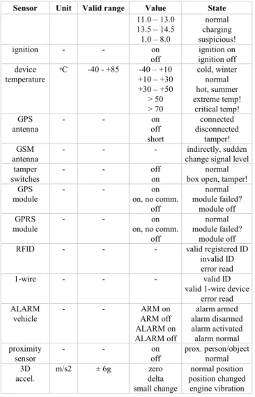
Before discussing the safety and security implications of the tracking device, we will overview some of the used sensors with valid ranges for their values and with the different individual possible states (see Table 1).
TABLE I. SENSORVALUES ANDSTATES Sensor Unit Valid range Value State internal battery Volts 3.7 – 4.2 ≤ 3.7≤ 4.0 4.0 – 4.2 ≥ 4.2 discharged low battery normal high, dangerous! internal
charger - - offon charger offcharger on external
battery Volts 11.0 – 14.5 8.0 – 11.0~ 0.0 disconnecteddischarged
Sensor Unit Valid range Value State 11.0 – 13.0 13.5 – 14.5 1.0 – 8.0 normal charging suspicious! ignition - - on
off ignition offignition on device temperature ᵒC -40 - +85 +10 – +30-40 – +10 +30 – +50 > 50 > 70 cold, winter normal hot, summer extreme temp! critical temp! GPS antenna - - offon short connected disconnected tamper! GSM
antenna - - - change signal levelindirectly, sudden tamper
switches - - offon box open, tamper!normal GPS
module - - on, no comm.on
off
normal module failed?
module off GPRS
module - - on, no comm.on
off
normal module failed?
module off
RFID - - - valid registered ID
invalid ID error read
1-wire - - - valid ID
valid 1-wire device error read ALARM
vehicle - - ARM offARM on
ALARM on ALARM off alarm armed alarm disarmed alarm activated alarm normal proximity
sensor - - offon prox. person/objectnormal 3D
accel. m/s2 ± 6g deltazero small change
normal position position changed engine vibration Various combinations of different sensor values can provide further information about possible events. For example, if we are looking at the battery, a value of 0V would mean that it was disconnected from the device, but it could also mean that the battery was completely removed from the vehicle. A historical analysis of past values for battery voltage values that measured show a slow decrease would indicate us that indeed the battery of the vehicle is discharged and that the user is replacing the battery. However, a situation where a 0V value and movements of the vehicle (as shown by the GPS receiver) are present, combined with the absence of the ignition signal, would definitely indicate that the tracking device was disconnected from the vehicle.
IV. SAFETY, SECURITY, PRIVACY INVEHICLETRACKING The tracking system and, especially, the tracking device have been designed keeping in mind many protections aiming to reduce safety risks, including, but not limited to, design safety features, system safety, and operational safety requirements.
First of all, the vehicle safety has been considered. The tracking device, which is considered to be mounted on the vehicle, must not interfere with any of the vehicle’s
systems or with the normal functioning of the vehicle. However, in order to obtain certain information about and from the vehicle, the connection of the tracking device to the vehicle’s systems was mandatory. Therefore, special cautions have been taken such that the tracking device is able to read information from the vehicle’s system without altering the original readings.
In Fig. 8 we present a diagram of the read-only (ro) connections of the tracking device to the car systems. Different data from the car’s system are read. Connection to the vehicle’s battery has been done in such way to avoid any possible power feedback or power surges from the device, in case of malfunctioning. For example, if there is a short circuit in the tracking device, it will automatically disconnect to avoid any interference with the car.
car alarm tracking device ro car battery (12/24V) ro CAN bus (engine) ro car ignition ro car systems
Figure 8. Connection of the tracking device to the car systems Connection to the car ignition signal has been done using electrically isolated opt couplers to avoid any feedback from the device. The connection to the car’s existing (factory built-in) or after marker alarm system has been performed similarly. Therefore, any possible malfunction of the tracking device would not affect, in any way, the normal operation of the alarm system.
The connection to the vehicle’s Engine Control Unit (ECU) has been done via the CAN bus. There are multitudes of engine parameters that can be read from the CAN bus, starting from engine speed (rpm), vehicle and wheel speeds, and ending with more complex fuel consumption readings. The connection to the CAN bus is a very convenient way of reading both several data from already existing sensors and information about the functioning of the engine and/or of the whole vehicle. However, connecting to such a bus is challenging from both the electrical interface point of view and the CAN protocol viewpoint. There are very strict limitations, and any failure or a wrong interface could severely alter the normal functioning of the engine, by altering the data flow on the bus. So, a direct electrical connection to the CAN bus has been out of the question, in order to not disrupt the functioning of the vehicle and not to violate the warranty, and also due to the high costs of such an interface. Alternatively, a read-only, passive interface has been chosen, which reads the signals from the CAN bus over the insulation of the wires, using a capacitive interface. The electrical signal variations from the wires are then converted to data and further to CAN messages, which are further interpreted by the tracking device. There is no feedback or interference from the tracking device to the CAN
bus, and, consequently, no alteration of the normal functioning is possible.
The safety of the tracking device has been another important issue to be considered. The main question to be asked has been the following:Could anything wrong happen to the device that might affect the car or the driver/passengers? One problem here was the fact that the tracking device had its own power source by means of an internal, rechargeable battery using Ion or Lithium-Polymer technology, which are known to produce possible unexpected safety events, like for example explosion. These are mainly due to overcharging or overheating of the battery. To cope with these undesired events, a very careful design of both the charging system and the battery overcharging protection, corroborated with constant monitoring of the device temperature have been performed. Several safety tests have been done, as well, and optimal heat dissipation has been analyzed using different techniques (from Peltier cooling units to careful design of the metallic enclosure to allow heat dissipation).
Next, the security of the tracking system has been considered. The main concern here has consisted of detecting, and possibly preventing and/or alerting the owner of any malicious intent that has had the potential to disrupt the normal functioning of the system. Further on, we will detail some of the security concerns of the tracking device, since it is the most vulnerable part of the system, and, in addition, it is located in a place mostly inaccessible to the tracking system manager. Moreover, the device could be mounted on a vehicle hundreds or even thousands of kilometers away from the location of the manager or any service unit. Therefore, we have given a great importance to both the reliability of the tracking device and to its security implications.
There are at least two possible situations when such a tracking device is mounted on a vehicle. The first one is when the actual driver of the car installs it for the purpose of monitoring its normal functioning, theft, hijack, crash, or accident. In this situation, we can assume that the owner will not intentionally tamper with the device or disrupt its normal functioning. However, the other parties involved might do that. The second situation is when the owner of the vehicle, who is different from the driver, installed the device, with the purpose of monitoring and penalizing the driver in case of misbehavior. This is usually true for company fleet management, where drivers are monitored not to use cars for personal aims, not to steal fuel, and not to drive with excessive speed. In these situations, there is a high probability that he or she will try to tamper with the functioning of the tracking device.
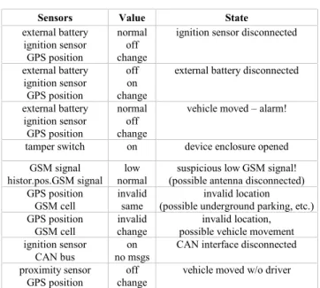
In Fig. 9, all the external connection of the tracking devices are shown, namely the wirings from the device to other equipments. All of them are susceptible to intervention from a malicious user. Some of them are easier to detect than others. In Table II, we present some of the situations we are able to detect based on combined information from different sensors.
Figure 9. External connections of the tracking device TABLE II. COMBINEDSENSORVALUES ANDSTATES
Sensors Value State
external battery ignition sensor GPS position normal off change
ignition sensor disconnected external battery ignition sensor GPS position off on change
external battery disconnected external battery ignition sensor GPS position normal off change
vehicle moved – alarm! tamper switch on device enclosure opened
GSM signal
histor.pos.GSM signal normallow (possible antenna disconnected)suspicious low GSM signal! GPS position
GSM cell invalidsame (possible underground parking, etc.)invalid location GPS position
GSM cell changeinvalid possible vehicle movementinvalid location, ignition sensor
CAN bus no msgson CAN interface disconnected proximity sensor
GPS position changeoff vehicle moved w/o driver For example, because the GPS positioning is critical to the tracking device, we have considered the situations where it might not function correctly and have tried to detect these situations. The critical part is the active GPS antenna. It is an antenna that is powered from the device and that contains a low-noise amplifier, which is capable of enhancing the signal from the satellites. Due to the nature of the signals, for optimal reception, the antenna must be positioned some distance away from the device, preferably in a clear-view of the sky position. The downside is that it allows the user to interfere with the antenna. If the user would disconnect the antenna, no signal would be received by the GPS, thus no position could be calculated. In a similar way, a short circuit on the antenna cable would disrupt its normal functioning. Even if these situations could not be recovered by the device, we can however detect both of them and alert immediately the fleet manager.
There is also the situation of jamming the GPS signal, which is easily detected by the system. However, a more sophisticated spoofing situation, where the GPS signal is intentionally modified in order to make the system believe that the device is in a different location than the real one, is much more difficult to detect. To generate this kind of attack, a very high cost device is necessary.
Last, the privacy of the data transmitted from the tracking device to the tracking system has been taken into account. The main concern here has been the prevention of any possibility that a third party intercepts the data transmitted from the device over the Internet (using GPRS), with the purpose of knowing the location of the vehicle. To do this, we have used different encryption algorithms for the data, directly on the device’s microcontroller. Also, the data sent from the device are all encrypted. The encryption keys are stored inside the microcontroller flash memory at programming time, and are protected from any external reading. Nobody could obtain these encryption keys, even if he would have physical access to the microcontroller.
V. CONCLUSION
So far, safety and security issues of vehicle tracking devices have been generally overlooked. The focus has been mostly on the security and privacy of accessing the actual information existing at the tracking centers, and less on the security of both the data recording device and the communication link.
In this paper, a vehicle tracking system is presented, zooming on the Gipix tracking device, which is presented and analyzed in more detail. Some of the main safety, security, and privacy issues are approached, along with a detailed analysis and discussion of possible solutions when tackling these situations. The increased complexity of the device, both hardware and software, and the multitude of situations related to safety and security that can arise require a unified framework. Future work will mainly focus on defining such a framework, and proactively implementing it in future versions of our system.
REFERENCES
[1] T. Aven, “A Unified framework for risk and vulnerability analysis covering both safety and security” inReliability Engineering and
System Safety, vol. 92, 2007, pp. 745-754.
[2] A. G. Hessami, “A Systems Framework for Safety and Security: The Holistic Paradigm” inSystems Engineering, vol. 7, no. 2, 2004, pp. 99-112.
[3] M. Gruteser, X. Liu, “Protecting Privacy in Continuous Location-Tracking Applications” in IEEE Security and Privacy, vol. 2, no. 2, 2004, pp. 28-34.
[4] J.P. Hubaux, S. Capkun, J. Luo, “The Security and Privacy of Smart Vehicles” inIEEE Security and Privacy, vol. 2, no. 2, 2004, pp. 49-55.
[5] M. Vladoiu, Z. Constantinescu, “Towards Location-based Services Using GPS-based devices”, inProc.of ICWN2008, International
Conference of Wireless Networks,London, 2008, pp. 799-804.
[6] Z. Constantinescu, C. Marinoiu, M. Vladoiu, “Driving Style Analysis Using Data Mining Techniques”, inInternational Journal of
Computers, Communications & Control (IJCCC),vol. V, no. 5, 2010,