Learning to Visually Predict Terrain Properties for Planetary Rovers by
Christopher A. Brooks
Bachelor of Science in Engineering and Applied Science California Institute of Technology, 2000
Master of Science in Mechanical Engineering Massachusetts Institute of Technology, 2004
Submitted to the Department of Mechanical Engineering in Partial Fulfillment of the Requirements for the Degree of
Doctor of Philosophy in Mechanical Engineering at the
Massachusetts Institute of Technology June 2009
© 2009 Massachusetts Institute of Technology. All rights reserved.
Signature of Author:
Department of Mechanical Engineering May 7, 2009
Certified by:
Karl Iagnemma Principal Research Scientist Thesis Supervisor Accepted by:
David Hardt Professor of Mechanical Engineering Graduate Officer, Department of Mechanical Engineering
Learning to Visually Predict Terrain Properties for Planetary Rovers by
Christopher A. Brooks
Submitted to the Department of Mechanical Engineering
on May 7, 2009, in partial fulfillment of the requirements for the degree of Doctor of Philosophy in Mechanical Engineering
Abstract
For future planetary exploration missions, improvements in autonomous rover mobility have the potential to increase scientific data return by providing safe access to geologically interesting sites that lie in rugged terrain, far from landing areas. This thesis presents an algorithmic framework designed to improve rover-based terrain sensing, a critical component of any autonomous mobility system operating in rough terrain. Specifically, this thesis addresses the problem of predicting the mechanical properties of distant terrain. A self-supervised learning framework is proposed that enables a robotic system to learn predictions of mechanical properties of distant terrain, based on measurements of mechanical properties of similar terrain that has been previously traversed.
The proposed framework relies on three distinct algorithms. A mechanical terrain characterization algorithm is proposed that computes upper and lower bounds on the net traction force available at a patch of terrain, via a constrained optimization framework. Both model-based and sensor-based constraints are employed. A terrain classification method is proposed that exploits features from proprioceptive sensor data, and employs either a supervised support vector machine (SVM) or unsupervised k-means classifier to assign class labels to terrain patches that the rover has traversed. A second terrain classification method is proposed that exploits features from exteroceptive sensor data (e.g. color and texture), and is automatically trained in a self-supervised manner, based on the outputs of the proprioceptive terrain classifier. The algorithm includes a method for distinguishing novel terrain from previously observed terrain. The outputs of these three algorithms are merged to yield a map of the surrounding terrain that is annotated with the expected achievable net traction force. Such a map would be useful for path planning purposes.
The algorithms proposed in this thesis have been experimentally validated in an outdoor, Mars-analog environment. The proprioceptive terrain classifier demonstrated 92% accuracy in labeling three distinct terrain classes. The exteroceptive terrain classifier that relies on self-supervised training was shown to be approximately as accurate as a similar, human-supervised classifier, with both achieving 94% correct classification rates on identical data sets. The algorithm for detection of novel terrain demonstrated 89% accuracy in detecting novel terrain in this same environment. In laboratory tests, the mechanical terrain characterization algorithm predicted the lower bound of the net available traction force with an average margin of 21% of the wheel load.
Thesis Supervisor: Karl Iagnemma
Acknowledgements
I would like to thank my adviser and the rest of my Ph.D. committee for their guidance and support of my research and this thesis. Their advice has greatly improved the quality of this work.
I would like to thank all of the people who helped me with my experiments with the TORTOISE rover. Maria Tanner, Matt Carvey, Shingo Shimoda, Ibrahim Halatci, and Marcos Berrios all contributed to the construction and assembly of the rover. I gratefully appreciate everyone who helped me in taking the rover to test sites around MIT and Gloucester, including Shingo Shimoda, Ibrahim Halatci, Chris Ward, Steve Peters, Sterling Anderson, Jon Brooks, and Artie Moffa. I hope you don’t hold it against me that “a day at the beach” always seemed to coincide with frigid temperatures. Except one gorgeous day in January.
For the experiments with the FSRL Wheel-Terrain Testbed, I have Shinwoo Kang to thank.
I would also like to thank all of the other members of the Field and Space Robotics Laboratory for making all of my hours in the lab more enjoyable, and my family and friends who made my time outside the lab something to look forward to. Most especially, I would like to thank my wife, Corinne, for her unending support and encouragement.
This work was supported by the National Aeronautics and Space Administration through the Mars Technology Program, and by the US Army Research Office.
Table of Contents
List of Figures ... 8
List of Tables... 11
Chapter 1 Introduction ... 13
1.1 Problem Statement and Motivation... 13
1.2 Purpose of this Thesis and Scenario Description ... 17
1.3 Background and Literature Review... 19
1.3.1 Mobility-related Terrain Sensing ... 19
1.3.2 Terrain Classification ... 23
1.3.3 Machine Learning ... 24
1.3.4 Mobility Prediction ... 26
1.4 Approach Overview ... 27
1.4.1 Learning From Experience... 28
1.4.2 Terrain Representation and Terminology ... 29
1.4.3 Self-Supervised Classification Framework and Algorithmic Components ... 33
1.5 Contribution of this Thesis... 37
1.6 Outline of this Thesis ... 37
Chapter 2 Proprioceptive Terrain Classification ... 39
2.1 Vibration-Based Terrain Classification... 39
2.1.1 Introduction ... 39
2.1.2 Approach ... 40
2.1.3 Experiment Details... 42
2.1.4 Results ... 46
2.1.5 Conclusions ... 48
2.2 Proprioceptive Terrain Clustering... 49
2.2.1 Introduction ... 49
2.2.2 Approach ... 52
2.2.3 Experiment Details... 56
2.2.4 Results ... 59
2.2.5 Conclusions ... 61
Chapter 3 Exteroceptive Terrain Classification ... 63
3.1 Visual Terrain Classification... 64
3.1.1 Introduction ... 64
3.1.2 Approach ... 65
3.1.3 Experiment Details... 73
3.1.4 Results ... 77
3.1.5 Conclusions ... 80
3.2 Visual Detection of Novel Terrain ... 80
3.2.1 Introduction ... 80
3.2.2 Approach ... 82
3.2.3 Experiment Details... 92
3.2.4 Results ... 94
Chapter 4 Mechanical Terrain Characterization ... 100 4.1 Introduction ... 100 4.2 Approach ... 102 4.2.1 Traversability Metric... 102 4.2.2 Terrain Sensing ... 105 4.2.3 Terrain Models ... 107
4.2.4 Optimization Framework Description... 111
4.3 Experiment Details... 120
4.3.1 FSRL Wheel-Terrain Interaction Testbed Experiments... 120
4.3.2 TORTOISE Experiments on Wingaersheek Beach ... 123
4.4 Results ... 126
4.4.1 FSRL Wheel-Terrain Interaction Testbed... 126
4.4.2 TORTOISE Rover on Wingaersheek Beach ... 131
4.5 Conclusions ... 133
Chapter 5 Self-Supervised Classification... 135
5.1 Experimental Validation of Self-Supervised Classification Framework ... 136
5.1.1 Introduction ... 136
5.1.2 Self-Supervised Classification Approaches ... 138
5.1.3 Experiment Details... 145
5.1.4 Results ... 148
5.1.5 Conclusions ... 158
5.2 Self-Supervised Terrain Learning System for Novel Environments ... 158
5.2.1 Introduction ... 158
5.2.2 Terrain Learning System Framework and Algorithmic Components ... 159
5.2.3 Experiment Details... 163
5.2.4 Results ... 164
5.2.5 Conclusions ... 169
Chapter 6 Conclusions and Suggestions for Future Work ... 170
6.1 Contributions of this Thesis ... 170
6.2 Suggestions for Future Work ... 172
References ... 174
Appendix A TORTOISE Rover Description ... 181
Appendix B Wingaersheek Beach Description ... 189
B.1 Sample Stereo Camera Images ... 193
Appendix C Wheel-Terrain Interaction Testbed Description ... 198
Appendix D Support Vector Machine Background and Optimizations... 202
D.1 C-Support Vector Classification ... 202
D.2 One-Class Support Vector Machine... 203
D.3 Kernel Functions ... 204
D.4 Optimizations for Linear and Polynomial Kernels... 205
Appendix E MATLAB Feature Extraction Code... 208
E.1 Vibration Feature Extraction ... 208
List of Figures
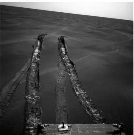
Figure 1-1. Deep tracks in Purgatory Dune left by MER Opportunity (Image courtesy
NASA/JPL-Caltech)... 15
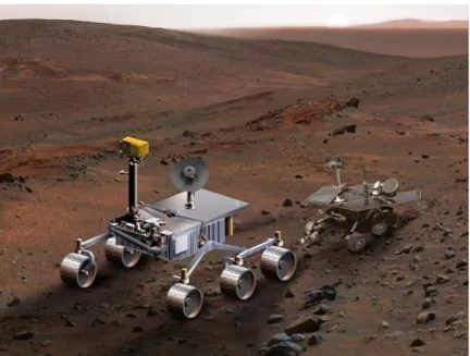
Figure 1-2. Artist concept of Mars Science Laboratory, left, compared to Mars Exploration Rover, right (Image courtesy NASA/JPL-Caltech)... 18
Figure 1-3. Schematic of proposed self-supervised classification framework... 28
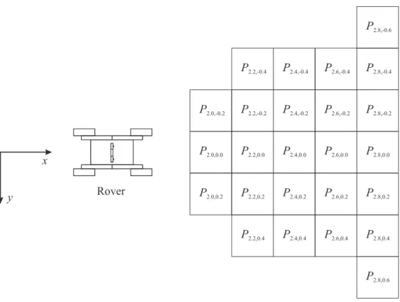
Figure 1-4. Sample overhead view showing regular grid of terrain patches in front of rover ... 30
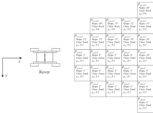
Figure 1-5. Sample terrain map showing data associated with terrain patches in front of rover (overhead view) ... 33
Figure 1-6. Information flow for self-supervised classification framework ... 34
Figure 1-7. Information flow for classification using exteroceptive terrain classifier... 36
Figure 2-1. Photo of TORTOISE, showing location of local sensor suite... 43
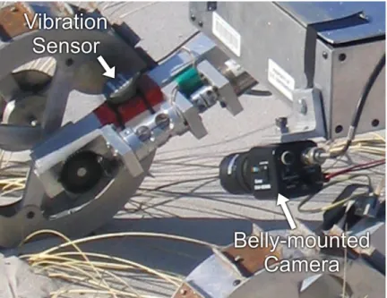
Figure 2-2. TORTOISE’s local sensor suite, with vibration sensor and belly-mounted camera ... 44
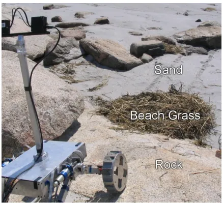
Figure 2-3. TORTOISE on Wingaersheek Beach, showing terrain classes... 45
Figure 2-4. ROC curve for vibration-based terrain classifier... 47
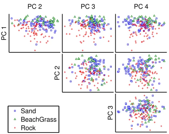
Figure 2-5. Vibration signals for three terrain classes plotted against first four principal components... 50
Figure 2-6. Scatter plot of three terrain classes illustrating overlap of statistics of time-windowed torque signal ... 51
Figure 2-7. Scatter plot of torque signals from three terrain classes with induced wheel slip ... 52
Figure 2-8. TORTOISE’s local sensor suite, with torque sensor and belly-mounted camera ... 57
Figure 3-1. Information flow for exteroceptive terrain classifier... 63
Figure 3-2. TORTOISE, showing location of stereo camera pair... 74
Figure 3-3. Sample image from stereo camera ... 75
Figure 3-4. TORTOISE on Wingaersheek Beach, showing terrain classes... 76
Figure 3-5. Representative ROC curves for visual terrain classifier... 78
Figure 3-6. ROC curves for baseline approaches and two-class classification approach for all data sets with rock as novel class ... 95
Figure 3-7. ROC curves for baseline approaches and two-class classification approach for all data sets with beach grass as novel class... 96
Figure 4-1. Wheel forces, torque, and sinkage... 103
Figure 4-2. Wheel forces on flat terrain (a) and slopes (b) ... 104
Figure 4-3. Nondimensionalized drawbar pull (DP/W) as a function of slip for four terrains ... 105
Figure 4-4. Absolute sinkage (a) vs. relative sinkage (b)... 106
Figure 4-5. Contact Region model ... 107
Figure 4-6. Bekker terrain model ... 109
Figure 4-7. Locations of concentrated stresses for lower bound ((a) or (b)), and upper bound ((c) or (d))... 114
Figure 4-8. FSRL wheel-terrain interaction testbed... 121
Figure 4-10. Photo of TORTOISE, showing location of local sensor suite... 124
Figure 4-11. TORTOISE’s local sensor suite, with torque sensor and belly-mounted camera ... 124
Figure 4-12. Testbed results for Contact Region Model with Absolute Sinkage (CRAS) ... 126
Figure 4-13. Testbed results for Bekker Model with Relative Sinkage (BRS)... 128
Figure 4-14. Testbed results for Bekker Model with Absolute Sinkage (BAS) ... 129
Figure 4-15. Comparison of testbed results for all approaches... 130
Figure 4-16. TORTOISE results for Bekker Model with Absolute Sinkage ... 132
Figure 5-1. Schematic of self-supervised classification, (a) vibration-supervised training of visual classifier, (b) prediction using visual classifier ... 138
Figure 5-2. Information flow in self-supervised classification framework during (a) training and (b) classification... 139
Figure 5-3. Information during training phase using local training approach ... 142
Figure 5-4. Sample image from belly-mounted camera... 142
Figure 5-5. Illustration of visual information being recalled in remote training approach ... 143
Figure 5-6. TORTOISE, showing location of stereo camera pair... 145
Figure 5-7. TORTOISE on Wingaersheek Beach, showing terrain classes... 147
Figure 5-8. ROC curves for self-supervised classifier using local training ... 150
Figure 5-9. ROC curves for manually trained classifier ... 151
Figure 5-10. ROC curves for self-supervised classifier using remote training ... 155
Figure 5-11. Information flow for self-supervised classification framework ... 159
Figure 5-12. Terrain learning system results, at t = 5.0 sec, distance traveled = 0.13 m, (a) 3-D view, (b) plan view showing terrain classes ... 165
Figure 5-13. Terrain learning system results, at t = 129.0 sec, distance traveled = 3.4 m, (a) 3-D view, (b) plan view showing terrain classes ... 166
Figure 5-14. Terrain learning system results, at t = 226.5 sec, distance traveled = 6.02 m, (a) 3-D view, (b) plan view showing classes ... 168
Figure A-1. Photo of TORTOISE, showing location of stereo camera pair ... 181
Figure A-2. Torque sensor mounted on TORTOISE ... 183
Figure A-3. Vibration sensor mounted on TORTOISE ... 184
Figure A-4. Belly-mounted camera on TORTOISE ... 184
Figure A-5. Rover communications schematic ... 186
Figure B-1. TORTOISE on Wingaersheek Beach, looking northeast towards Annisquam lighthouse. Mats of beach grass lie between TORTOISE and the rock outcrops. .. 189
Figure B-2. TORTOISE on Wingaersheek Beach, looking southeast towards Goose Cove. A long stretch of sand with occasional mats of beach grass lies between the rover and the distant rock outcrop... 190
Figure B-3. TORTOISE (distant) on Wingaersheek Beach, looking northwest. A band of small, loose stones divides sections of washboard-textured sand between the camera and TORTOISE... 191
Figure B-4. Chris Ward and TORTOISE on Wingaersheek Beach, looking southwest. Large mats of dark beach grass lie over the sand between the camera and TORTOISE... 192
Figure B-6. Sample image from Image Set 1 (Nov 30, 2006, Run 2)... 194
Figure B-7. Sample image from Image Set 2 (Dec 7, 2006, Run 4) ... 194
Figure B-8. Sample image from Image Set 3 (Dec 7, 2006, Run 5) ... 195
Figure B-9. Sample image from Image Set 4 (Dec 7, 2006, Run 6) ... 195
Figure B-10. Sample image from Image Set 5 (Dec 14, 2006, Run 1) ... 196
Figure B-11. Sample image from Image Set 6 (Dec 14, 2006, Run 2) ... 196
Figure B-12. Sample image from terrain learning system for novel environments image set (Oct 30, 2007, Run 5) ... 197
Figure C-1. Wheel-terrain interaction testbed, with dimensions ... 198
List of Tables
Table 2-1. Pseudocode for k-Means Clustering Algorithm... 56
Table 2-2. Performance of Proprioceptive Terrain Clustering Algorithm ... 60
Table 3-1. Performance of Visual Terrain Classifier ... 79
Table 3-2. Comparison of Novel Terrain Detection Approaches ... 97
Table 4-1. Bekker Model Parameters... 110
Table 4-2. Ranges for Bekker Parameters... 111
Table 4-3. Optimization Parameters for Bekker Model with Relative Sinkage... 117
Table 4-4. Optimization Parameters for Bekker Model with Absolute Sinkage ... 119
Table 4-5. Summary of Testbed Results ... 131
Table 5-1. Comparison of Self-Supervised Classification Using Local Training to Manually Supervised Classification... 152
Table 5-2. Comparison of Self-Supervised Classification Using Remote Training to Manually Supervised Classification... 156
Table 5-3. Class Labels and Associated DP/W Ranges ... 161
Table A-1. TORTOISE Dimensions ... 182
Table A-2. TORTOISE Motors and Transmissions... 183
Table A-3. TORTOISE Sensors... 184
Table A-4. TORTOISE PC104 System Components ... 187
Table C-1. Specifications for Black Plastic Wheel Assembly ... 200
Table C-2. Wheel-Terrain Interaction Testbed Carriage Drive Specifications... 201
Table D-1. Kernel Types and Corresponding Equations ... 205
Table E-1. Vibration Feature Extraction Code... 209
Chapter
1
Chapter 1Introduction
1.1 Problem Statement and Motivation
The ability for humans to explore the surface of other planets using mobile robots (“rovers”) is fundamentally dependent on the autonomous mobility capabilities of these robots. Because targets of scientific interest such as craters, ravines, and cliffs present dangers to landing, planetary rovers must land at safe locations and travel long distances to reach these targets (NASA/JPL, 2007). Close teleoperational supervision of robots is not desirable because limited communication with operators on Earth places significant restrictions on the distance a rover can travel during a mission lifetime—for each downlink/uplink cycle of roughly 24 hours (Mishkin & Laubach, 2006), the rover cannot safely travel beyond the distance it can image with its cameras, which has been as little as 15 meters or less in dune fields observed by the Mars Exploration Rovers (NASA/JPL, 2005). Thus, advances in robot autonomy will lead to payoffs in terms of scientific data return from locations that were previously unreachable, since it will allow rovers to travel longer distances with limited human supervision.
One current limitation to autonomous mobility is the rover’s inability to autonomously identify terrain regions that can be safely traversed. Existing path planning
algorithms can generate a route to a target that avoids known obstacles only if they are given an accurate map of the ease of traversability of the surrounding terrain (Nilsson, 1982; Stentz, 1994; Goldberg, Maimone, & Matthies, 2002). Unknown hazards have the potential to immobilize the rover, delaying or permanently preventing completion of the mission. Thus, autonomous navigation is generally restricted to environments which operators have previously determined to be relatively benign. The ability to autonomously detect possible hazards from a safe distance would enable safe autonomous travel in previously unexplored rough terrain.
While geometric1 hazards, such as large rocks or cliffs, can be sensed remotely using range sensing techniques (Talukder et al., 2002), little research has addressed remote sensing of non-geometric hazards, such as loosely packed soil or sandy slopes. The importance of sensing non-geometric hazards was highlighted in April 2005, when the Mars Exploration Rover (MER) Opportunity became entrenched in a dune composed of loosely packed drift material (Cowen, 2005). Figure 1-1 shows the deep tracks left in the dune after Opportunity extricated itself. The terrain geometry was not hazardous, as the rover could have easily traversed the dune if it were made of a material with more favorable terrain properties, such as rock or packed soil. On the contrary, it was the mechanical properties of the terrain surface which made it a hazard—the high compactability of the loose drift material caused the wheels to sink deeply into the surface, and the combination the drift’s low internal friction and the motion resistance due to sinkage prevented the rover from producing sufficient thrust to travel up the slope.
1
Here, geometric hazards are considered to be obstacles which prevent safe travel of a rover due primarily to their shape, and not to loss of traction between a wheel and the terrain. In contrast, non-geometric hazards are regions of terrain which are impassible due to their limited traction properties (or a combination of the limited traction and terrain geometry) which could lead to rover immobilization.
Opportunity’s progress was delayed for more than a month while engineers worked to extricate it.
Figure 1-1. Deep tracks in Purgatory Dune left by MER Opportunity (Image courtesy NASA/JPL-Caltech)
Since non-geometric hazards are highly dependent on wheel-terrain interaction properties, methods for characterizing such hazards have focused on measuring aspects of that interaction. Examples include wheel sinkage measurement (Brooks, Iagnemma, & Dubowsky, 2006; Wilcox, 1994), parametric soil characterization (Iagnemma, Kang, Shibly, & Dubowsky, 2004), wheel slip detection (Reina, Ojeda, Milella, & Borenstein, 2006), and explicit traversability estimation (Kang, 2003). These methods rely on
proprioceptive2 terrain sensing, which characterizes only the terrain immediately under the rover wheel, so it is of limited use for predictive hazard avoidance.
Where researchers have addressed terrain sensing using exteroceptive sensors, such as cameras or LIDAR sensors, it has typically been assumed that the visual appearances of terrain classes of interest are known a priori (Angelova, Matthies, Helmick, & Perona, 2007a; Wellington, Courville, & Stentz, 2005). Although (Kim, Sun, Oh, Rehg, & Bobick, 2006) describes an approach for distinguishing traversable from non-traversable terrain where the terrain class appearances are learned, their work focuses on the detection of geometric hazards. No research has addressed the detection of non-geometric hazards using exteroceptive sensors, where the visual appearance of the terrain classes is not known a priori.
In summary, autonomous planetary rover mobility is significantly affected by the mechanical properties of terrain, which to date have been identified only for terrain physically contacted by the rover or for terrain classes known a priori. In environments where the visual appearances of terrain classes are not known a priori, no framework exists for autonomously predicting the mechanical properties of distant terrain, such that these properties can be used for autonomous navigation and hazard avoidance. Such an approach would greatly increase a rover’s ability to autonomously navigate to distant sites of scientific interest.
2
Proprioceptive sensors measure the internal state of the rover, and therefore sense terrain through its interaction with the rover. In this work, wheel torque, wheel speed, and wheel sinkage are considered to be measured by proprioceptive sensors.
1.2 Purpose of this Thesis and Scenario Description
The purpose of this thesis is to develop a framework and the underlying algorithmic components to enable a planetary rover to accurately predict mechanical properties of distant terrain, by learning from its experience in traversing similar terrain. In particular, this work is concerned with 1) the estimation of mechanical properties relevant to robotic mobility prediction, and with 2) associating these mechanical properties with visual features, such that the mechanical properties can be reliably identified from a distance of several meters. To minimize the time between terrain sensing and terrain property prediction, emphasis will be placed on using algorithms that are computationally inexpensive, such that they can be executed in seconds or minutes on COTS hardware.
The scenario assumed for this work is one of planetary exploration, loosely modeled on the sensing, mobility, and predicted environment of the Mars Science Laboratory (MSL) mission, a large, six-wheeled rover scheduled for launch to Mars in 2011 (J. Johnson, 2008; NASA/JPL, 2008b). (Figure 1-2 shows an artist’s concept of the MSL on Mars.) In this scenario, communication delays of 8 to 40 minutes (round-trip) and a communication bandwidth of approximately 7.5 MB per day necessitate the use of autonomous navigation to reach targets of interest at least 20 km away3. (For comparison, Opportunity and Spirit, which have been on Mars for nearly 5 years, are only now on the verge of having traveled 20 km combined (NASA/JPL, 2008a).) The challenge of terrain sensing is eased by the fact that the environment can be considered as static—any obstacles will remain stationary—and the robot is slow-moving, traveling at a speed of 5
3
to 15 cm per second. However computation is limited,4 and a very high cost of failure requires that any approach tend to minimize risk of failure.
Figure 1-2. Artist concept of Mars Science Laboratory, left, compared to Mars Exploration Rover, right (Image courtesy NASA/JPL-Caltech)
In this thesis it is assumed that the rover will be able to measure wheel torque, sinkage of a rigid wheel into deformable terrain, and vibrations in the rover suspension arising from wheel-terrain interaction. Wheel torque can either be measured with a dedicated torque sensor, or estimated from motor current and wheel speed using a Kalman filter. Wheel sinkage can be measured visually based on images containing the rover wheels as in (Brooks et al., 2006), or the relative wheel sinkage between two positions on the rover path can be calculated as in (Wilcox, 1994). It should be noted that wheel torque and sinkage measurement can be implemented with no additional hardware beyond that planned for MSL. Rover suspension vibration can be sensed using an inexpensive contact microphone or accelerometer.
4
MSL has a radiation-hardened version of IBM’s PowerPC 750 running at 200 MHz (Bajracharya, Maimone, & Helmick, 2008). For reference, the PowerPC G3 line of Macintosh desktop computers based around the PowerPC 750 were sold between November, 1997 and July, 2001.
It is also assumed that the rover will be equipped with a stereo pair of mast-mounted cameras to sense the color and geometry of terrains from 1 meter to 20 meters away. This sensing is currently planned for inclusion on MSL as a pair of monochrome cameras with filter wheels. The last assumption is that the rover will be able to measure its speed relative to the terrain. This is currently implemented on the Mars Exploration Rovers via a visual odometry algorithm (Maimone, A. Johnson, Cheng, Willson, & Matthies, 2006).
1.3 Background and Literature Review
This thesis draws on techniques from the machine learning and machine vision fields, as well as research in terrain parameter estimation and mobility prediction. While most previous works in robotic terrain estimation have addressed only a subset of these research areas, some recent works have presented coherent approaches to mobility-related terrain sensing. These works will be described in the first subsection. Other subsections address previous work related to the algorithmic components of this thesis, including terrain recognition, machine learning, and mobility prediction.
1.3.1 Mobility-related Terrain Sensing
Terrain sensing is a broad field addressing the interpretation of sensor data to yield information about a terrain region. Here, mobility-related terrain sensing refers to approaches for associating sensor data with vehicle mobility. Some approaches operate on data from only proprioceptive sensors (e.g. vibration or wheel sinkage data), and thus address the rover’s mobility on the terrain immediately beneath the rover’s wheels. Other
approaches operate on data from exteroceptive sensors (e.g. vision or LIDAR data), and are used to predict the mobility properties of terrain several rover lengths away.
1.3.1.1
Binary Hazard Detection
Historically, mobility-related terrain sensing has focused on binary hazard detection (Bellutta, Manduchi, Matthies, Owens, & Rankin, 2000; Henriksen & Krotkov, 1997). In this paradigm, regions of terrain are deemed either traversable (i.e. non-hazards) or non-traversable (i.e. non-hazards), with no quantitative measure of traverse difficulty or uncertainty. Most research has assumed that these hazards are physical obstacles geometrically distinct from the surrounding terrain, and thus addresses the extraction of obstacles from a 2½-D or 3-D representation of the scene. A fully 3-D obstacle detection scheme is presented in (Talukder, Manduchi, Rankin, & Matthies, 2002). It relies on detecting abrupt changes in the terrain height. An extension to this work, presented in (Talukder et al., 2002), includes the visual appearance of terrain in the obstacle detection process, where the visual appearance is used to determine which of the geometrically detected obstacles are likely to be traversable despite their geometry (e.g. tall grass). It assigns a traversability metric in the form of a maximum safe driving speed, however this is based solely on analysis of 3-D geometry. Thus, the work does not address the detection of non-geometric obstacles, which is the primary focus of this thesis.
Other work in binary hazard detection relies on color and LIDAR data to estimate the geometry of a load-bearing surface in the presence of thick vegetation (Wellington et al., 2005). A hidden semi-Markov model is used as a framework to filter the sensor data and distinguish vegetation from solid ground. While this approach includes a component
of terrain sensing relevant to mobility, the surface type (i.e. vegetation or solid ground) is not used for traversability estimation. It therefore does not attempt to detect non-geometric hazards.
More recently, researchers have attempted to learn to distinguish traversable terrain from non-traversable terrain using a combination of color, visual texture, and geometry (Kim et al., 2006). Their approach is conceptually similar to the one presented in this thesis, in that the rover learns from its experiences. The rover initially plans a path assuming that all terrain is traversable, then learns to recognize the visual appearance of obstacles when it contacts terrain that impedes its motion. Their approach differs from the one presented in this thesis in that they assume a strict dichotomy between traversable and nontraversable terrain, as opposed to the gradations of traversability considered in this thesis. In addition, their approach is designed for an environment in which none of the terrain would be treacherous to attempt to traverse, because its only method for identifying non-traversable terrain is physical contact with an object impeding its motion. In contrast, the approach presented in this thesis could be used to predict robot mobility on impassable slopes composed of a given terrain, even if a rover’s only experiences with the terrain were on marginally traversable flat ground. Also, as with (Talukder et al., 2002), the work focuses on identifying terrain which is likely to be traversable despite its geometry, such as tall grass.
1.3.1.2
Proprioceptive Terrain Sensing
Other work has addressed the issue of distinguishing non-geometric hazards using proprioceptive sensors. (Wilcox, 1994) describes a method for wheel sinkage detection using suspension configuration sensors. Another method measures wheel sinkage using
images from a camera with a view of the wheel, by detecting the intensity difference between the wheel and the terrain (Brooks et al., 2006). These approaches are useful for identifying when a rover is in danger of becoming entrenched, but they cannot be used to predict the traversability of distant terrain, since they can only be used to sense terrain immediately under the rover’s wheels.
Since excessive wheel slip is the failure mode for non-geometric hazards, terrain sensing approaches that estimate wheel slip are also useful in the context of rover mobility. For this reason, several researchers have focused on using proprioceptive sensors to detect wheel slip (Ojeda & Borenstein, 2002; Ojeda, Cruz, Reina, & Borenstein, 2006; Reina et al., 2006; Ward & Iagnemma, 2007). Again, however, the reliance on proprioceptive sensor data prevents easy generalization to the prediction of properties of distant terrain.
1.3.1.3
Exteroceptive Traversability Sensing
To provide a useful prediction of the properties of terrain that lies more than one rover-length away, some researchers have used a learning framework similar to the one presented in this thesis. Researchers at JPL have attempted to model wheel slip as a function of visual and geometric terrain properties, where the wheel slip model is adapted on-line (Angelova et al., 2007a, 2007b; Angelova, Matthies, Helmick, Sibley, & Perona, 2006). They achieve good slip prediction results using an empirically generated slip model. However their approach assumes that the visual appearance of terrain classes is known a priori. Thus it would be inappropriate for use in an environment where the rover might encounter unexpected terrain.
Another group has implemented self-supervised learning for terrain sensing on a larger scale (Sofman et al., 2006). They attempt to generalize a LIDAR-based traversability metric, accurate at a range of tens of meters, to the kilometer-scale field of view of an aerial camera. They succeed in improving the look-ahead range for path planning, but their traversal cost values have no physical interpretation, so there is no obvious method to quantify the accuracy of their traversability map. Also, they assume that color from an overhead image directly maps to traversability without regard to topography. This is unlikely to hold in the planetary exploration setting, where changes in terrain slope may not be accompanied by changes in terrain color.
1.3.2 Terrain Classification
Terrain classification has received significant attention for the purposes of both robotic autonomy and remote science. Terrain classification based on satellite imagery has been commonly used by scientists for land use monitoring, e.g. (Berni, Zarco-Tejada, Suarez, & Fereres, 2009; Olsen, Garner, & Van Dyke, 2002). Unfortunately, many of these approaches involve classification using a dozen or more wavelength bands, requiring sensors which are not typically available on planetary rovers. These approaches also ignore the potentially useful texture and geometry data that is available to ground-based robots, which operate in close proximity to the terrain.
In the field of robotics, terrain classification at a distance of several meters has been achieved using color, texture, geometry (via stereo or LIDAR), and even polarization data (Denes, Gottlieb, Kaminsky, & Huber, 1998). A variety of texture discrimination metrics have been described, including Gabor filters (Weldon, Higgins, & Dunn, 1996), wavelet-based fractal dimensions (Espinal, Huntsberger, Jawerth, &
Kubota, 1998), and receptive fields inspired by the human visual system (Balas, 2006; Malik & Perona, 1990). Various approaches for combining color, texture, and geometry have been proposed including naïve Bayes fusion (Shi & Manduchi, 2003), neural networks (Rasmussen, 2002), meta-classifier fusion (Halatci, Brooks, & Iagnemma, 2008), and semi-supervised fusion (Manduchi, 1999). These approaches are typically used in a supervised fashion, where the number and appearance of classes is known a priori. While (Rasmussen, 2002) addresses the classification problem in the context of road detection, most approaches make no attempt to associate traversability with the classification result. It should be noted that the work in this thesis relies on the visual classifier developed by Halatci, so Section 1.1 closely follows the approach presented in (Halatci, 2006; Halatci et al., 2008).
A limited amount of work has been performed in the area of classification based on proprioceptive terrain sensors such as accelerometers. Such an approach was proposed in (Iagnemma & Dubowsky, 2002), and a functional algorithm was presented in (Brooks & Iagnemma, 2005). A similar algorithm, intended for high-speed ground vehicles, was presented in (DuPont, Roberts, Selekwa, C. Moore, & Collins, 2005; Sadhukhan, 2004). These approaches are useful in classifying the terrain in contact with the rover’s wheels, and the approach of Brooks & Iagnemma is described in Section 2.1 for this purpose. However due to its reliance on proprioceptive sensor data, this algorithm cannot be applied directly to classify terrain not in contact with the rover.
1.3.3 Machine Learning
The terrain classification and clustering approaches presented in this thesis take advantage of work in the field of machine learning. While both classification and
clustering have been studied extensively, only a small subset of the previously developed approaches are appropriate for use in a learning framework operating in a time-constrained scenario, and these will be described below.
For classification, support vector machines (SVM) have received significant attention due to the speed at which they can be trained as well as their success in classifying data from a wide variety of datasets (Schölkopf, 2000; Vapnik, 2000). Recent work has provided strict bounds on the classification error rate, given the error rate over the training data (Rakhlin, Mukherjee, & Poggio, 2006). An implementation of an SVM has also been developed for online applications, where training data is presented as a sequence rather than as a single batch (Kivinen, Smola, & Williamson, 2004). It is not appropriate for this thesis, however, because it relies on the conditional independence of sequential training examples—a poor assumption in the scenario considered here. SVM classifiers can be implemented with linear or polynomial kernels, which can reduce both training and classification time in situations when there is a large number of training examples. Details related to reducing the SVM classification time are presented in Appendix D, and SVMs are used extensively in this thesis.
Clustering, as opposed to classification, is a machine learning technique appropriate for situations when the classes are not known a priori, or when labeled training data is not available. It is the task of dividing unlabeled points into “clusters” of similar points. Traditional methods of clustering include the well-known k-means method as well as linkage-based methods derived from graph theory (Bishop, 1995; Brandes, Gaertler, & Wagner, 2003). These methods all rely heavily on the features used to
represent the data. They have not previously been applied to traversability-related terrain segmentation.
Another area of machine learning related to this research is that of novelty detection. Novelty detection is the task of classifying a point as “same” or “different” as compared to the training data, where there are no explicit examples of what is “different.” This has occasionally been referred to as “one-class classification,” and a one-class variant of the SVM classifier has been proposed (Schölkopf, Platt, Shawe-Taylor, Smola, & Williamson, 2001). Another approach is to model the distribution of the training data, for example using a mixture of Gaussians (MoG) model, and to label a new point as “different” if the modeled density at that point is lower than some threshold. A theoretical analysis of single-class classification strategies was presented in (El-Yaniv & Nisenson, 2007), and this analysis was the inspiration for the approach presented in 1.1. These novelty detection approaches have not previously been applied to terrain identification.
1.3.4 Mobility Prediction
An important aspect of mobility prediction is modeling the interaction between a wheel and the terrain. (Bekker, 1969) is the authoritative work in this field, describing measurable mechanical properties of deformable terrain and defining the relationship between these properties and the net forces and torques acting between the wheel and terrain. Similar work by Wong and Reece differs only in the role of wheel width in the force and torque equations (Wong, 2001; Wong & Reece, 1967). Both of these approaches require the use of dedicated equipment to measure the terrain properties.
To enable parametric terrain modeling in scenarios without dedicated equipment, Iagnemma proposed an approach for estimating terrain parameters using measurements
of the net forces and torques on a wheel (Iagnemma, Shibly, & Dubowsky, 2002; Iagnemma et al., 2004). It was demonstrated that a Kalman filter could be used to estimate the coefficients of a reduced-order Bekker model during a rover traverse. However the estimated terrain properties were not used to predict a measure of traversability of terrain. Kang extended that work and proposed a nondimensionalized drawbar pull—the drag force that would be required to hold the vehicle stationary—as a traversability metric (Kang, 2003; Iagnemma, Kang, Brooks, & Dubowsky, 2003). Kang proposed an approximate equation for drawbar pull as a function of wheel sinkage, wheel torque and vertical load.
Other researchers have attempted to quantify traversability in other ways. In (Seraji, 1999) a traversability index based on fuzzy logic was calculated as a function of terrain slope, rock size, and rock concentration. Another approach, the T-transformation, calculated a traversability index based on terrain slope and geometric roughness of the terrain (Ye & Borenstein, 2004). Neither of these approaches considered the mechanical properties of the terrain, making them incompatible with the notion of non-geometric hazards presented in this thesis.
1.4 Approach Overview
In order to appreciate the relationship between the algorithmic components developed in this thesis, it is useful to understand how they are integrated in an online terrain sensing framework. This section presents the concept of learning from experience, defines the terrain representation and terminology that will be used throughout the thesis, and then describes how each of the algorithmic components fit into the overall self-supervised learning framework.
1.4.1 Learning From Experience
As described in 1.2, the purpose of this thesis is to allow a rover to learn the relationship between mechanical terrain properties and terrain appearance, to enable it to predict the mechanical properties of distant terrain. Figure 1-3 illustrates the three stages of this learning process.
Figure 1-3. Schematic of proposed self-supervised classification framework
Initially, the rover has no knowledge of the relationship between the terrain appearance and its mechanical properties. From a given position, it is assumed that a
rover can sense the appearance of terrain using cameras (Figure 1-3(a)), but cannot yet predict its ability to traverse this terrain.
Figure 1-3(b) shows the rover after it has driven onto a patch of terrain that it previously sensed with its cameras. Using proprioceptive sensors (e.g. vibration sensors or torque sensors), the rover can sense the interaction between the rover wheels and terrain, and thus characterize the mechanical terrain properties which affect the mobility of the rover.
Once the rover has sensed the appearance of a patch of terrain and characterized its effect on rover mobility, it associates the features related to appearance with mobility properties. From this association, the rover can sense the appearance of terrain it has not yet traversed and predict that effect that terrain may have on the rover (Figure 1-3(c)). Thus, the rover has learned to predict the mobility properties of distant terrain from its experiences traversing terrain with a similar appearance.
1.4.2 Terrain Representation and Terminology
To avoid ambiguity in the description of the self-supervised classification framework and its algorithmic components, it is necessary to establish terminology to describe the terrain and the rover’s sensors. This section introduces terminology for terrain patches, mechanical terrain properties, terrain classes, proprioceptive and exteroceptive sensors, and the terrain map.
Terrain Patch
In this thesis, terrain around a rover is divided into a regular grid of 20 cm by 20 cm terrain patches, whose locations are fixed in inertial space. Each patch is identified by
an x-coordinate indicating distance in front of the rover’s starting position, and a y-coordinate indicating distance to the right of the rover’s starting position, as illustrated in Figure 1-4. Thus, a terrain patch P2.2,0.4 is the region of terrain located between 2.2 meters
and 2.4 meters forward of the rover starting position, and between 0.4 and 0.6 meters right of the rover starting position. This grid is fixed with respect to the ground, so that as the rover travels its wheels come into contact with multiple terrain patches.
Figure 1-4. Sample overhead view showing regular grid of terrain patches in front of rover Because terrain is generally not flat, each of the terrain patches may have non-planar topography. That topography is represented by a set of points in 3-D space located on the surface of the terrain. Since this grid-based representation has difficulty representing overhangs, it is assumed that no two points on the terrain surface are directly above one another (i.e. a 2½-D representation is assumed).
Mechanical Terrain Properties
For this thesis, mechanical terrain properties are measurable quantities that can be used to describe the forces and torques between a rover wheel and the terrain. For example, one mechanical terrain property is the maximum thrust force that a rover wheel could exert when in contact with a terrain patch. Here, the primary interest is in mechanical terrain properties that are useful in determining whether a terrain patch may be traversed safely.
Terrain Class
It is assumed that each terrain patch Px,y can be uniquely associated with a terrain
class (e.g. “sand,” “rock,” and “beach grass”). A terrain class is a categorization for a terrain patch based on its mechanical properties: a terrain patch Px1,y1 associated with
terrain class “sand” will react differently to forces applied by the rover’s wheel than would a terrain patch Px2,y2 associated with terrain class “rock.” In this thesis, terrain
classes are categorizations of the mechanical properties of the terrain without regard to its topography. Thus, patches Px1,y1 and Px2,y2 may be associated with the same terrain class
even if Px1,y1 is nearly flat and Px2,y2 has a steep slope.
It should be noted that terrain classes may be defined by human supervisors based on prior knowledge of the rover’s environment, or they may be discovered by the rover through unsupervised learning (i.e. clustering). Human-defined terrain classes typically have some clear semantic interpretation: “sand,” “rock,” and “beach grass” are all easily understood. Terrain chasses discovered through clustering are not associated with semantic labels, so interpretation of the distinctions between classes may be more difficult.
Proprioceptive and Exteroceptive Sensors
Various sensors are used by the rover to sense its environment. These sensors are either exteroceptive or proprioceptive. Exteroceptive sensors, such as cameras, are able to directly sense features related to terrain. Proprioceptive sensors, such as wheel torque sensors or vibration sensors, are able to sense features related to the terrain only through the physical interaction between the rover wheels and terrain.
Because proprioceptive sensors function by measuring characteristics of wheel-terrain interaction, they are restricted to sensing wheel-terrain in direct contact with a rover wheel. In this thesis, sensor data is denoted S, with indices specifying the sensor and the time at which the sensor reading was recorded, for example Storque,t=0. Given the position
of the rover, it is trivial to identify the terrain patch Px,y with which proprioceptive sensor
data Storque,t=0 is associated.
Exteroceptive sensors can sense features related to terrain not in contact with the rover, and thus sensor data associated with multiple terrain patches may be sensed simultaneously. For example, an image Scamera,t taken at time t can contain pixels
associated with multiple terrain patches. To identify the terrain patch associated with a given pixel Scamera,t,i,j located at row i and column j, the (stereo-derived) range data
associated with that pixel (Srange,t,i,j) is needed, as well as the rover’s position and
orientation at time t.
Terrain Map
A terrain map is a rover’s internal representation of the surrounding terrain around it. For this thesis, that representation includes the topography of each terrain patch that has been previously sensed, as well as the associated terrain class and mechanical terrain
properties. A sample terrain map is shown in Figure 1-5. Mechanical terrain properties calculated from proprioceptive sensor data are associated with terrain patches for which this proprioceptive data is available. Prediction of mechanical terrain properties for terrain patches which have not been sensed using proprioceptive sensors is the focus of this thesis.
Figure 1-5. Sample terrain map showing data associated with terrain patches in front of rover (overhead view)
1.4.3 Self-Supervised Classification Framework and Algorithmic
Components
In this framework, the learning process is divided among three distinct algorithms. The information flow between these algorithms is shown in Figure 1-6. The first algorithm is a proprioceptive terrain classifier, which takes proprioceptive sensor
data (e.g. wheel torque, sinkage, or vibration) as an input and returns a terrain class label as its output. The second algorithm is an exteroceptive terrain classifier, which is trained using labels from the proprioceptive terrain classifier.5 Once trained, it takes exteroceptive sensor data (here, color stereo images of the terrain) as its input and returns terrain class labels for each of the terrain patches in its field of view. The third algorithm is a terrain characterization algorithm, which uses proprioceptive sensor data to estimate the mechanical terrain properties associated with each terrain class. The output of these three components is a terrain map that contains information about the mechanical terrain properties and topography of the terrain patches around the rover.
Figure 1-6. Information flow for self-supervised classification framework
Each of these algorithmic components is described in a separate chapter of this thesis. Proprioceptive terrain classification is presented in Chapter 2, exteroceptive terrain classification is presented in Chapter 3, and mechanical terrain characterization is presented in Chapter 4. The following subsections describe each of these algorithms in more detail.
5
This approach is referred to as self-supervised classification because one classifier (in this case, the exteroceptive terrain classifier) is trained using data labeled by another classifier (in this case, the proprioceptive terrain classifier). In contrast, a supervised classifier is trained using data labeled by a human supervisor.
1.4.3.1
Proprioceptive Terrain Classification
The purpose of proprioceptive terrain classification is to classify terrain patches based on proprioceptive sensor data, such that terrain patches with similar mechanical properties are associated with the same terrain class, and terrain patches with significantly different mechanical properties are associated with different terrain classes. There are a number of potential approaches for accomplishing this task. This thesis presents three distinct approaches.
The first approach, presented in 2.1, relies on training of a supervised classifier to identify terrain classes based on proprioceptive sensor data, where these terrain classes are defined by a human supervisor during training. This requires a priori knowledge of the terrain classes in the rover’s environment, and hand labeling of training data.
The second approach, investigated in 2.1, relies on unsupervised clustering to group terrain patches into classes based on proprioceptive sensor data. This approach eliminates the need for hand labeling of data. However, the terrain clusters are not associated with meaningful labels, so interpretations of the distinctions between terrain classes may be difficult. Also, this approach may require more clustered terrain classes to adequately represent the terrain compared to the first approach.
In the third approach, briefly addressed in 1.1, terrain patches are classified based on the mechanical terrain properties identified by the mechanical terrain characterization algorithm. Here, terrain classes are defined a priori to correspond to a range of mechanical terrain properties. This requires that the mechanical terrain characterization algorithm be executed frequently to accumulate training data for the exteroceptive terrain classifier, which may be more computationally expensive than either of the first two
approaches due to the nonlinear optimizations involved in computing the mechanical terrain properties.
1.4.3.2
Exteroceptive Terrain Classifier
The purpose of exteroceptive terrain classification is to classify terrain patches based on features derived from exteroceptive sensor data—in this case, color, visual texture, and topography. The approach proposed in this thesis is to use a two-stage classification process, as shown in Figure 1-7. First, a novel terrain detection stage identifies whether the terrain patch belongs to a known class. If the patch belongs to one of the known classes, the known terrain classifier is invoked. Otherwise, the patch is labeled as “unrecognized” in the terrain class map. The exteroceptive terrain classification algorithm is presented in Chapter 3.
Figure 1-7. Information flow for classification using exteroceptive terrain classifier
1.4.3.3
Mechanical Terrain Characterization
The purpose of mechanical terrain characterization is to use proprioceptive sensor data to identify mechanical properties associated with a terrain patch. The approach presented in this thesis establishes bounds on the net traction force available at a given terrain patch. This approach is described in Chapter 4.
1.5 Contribution of this Thesis
The contribution of this thesis is the development and analysis of a self-supervised learning framework and component algorithms. This framework enables a planetary rover to accurately predict mechanical properties of terrain at a distance by learning from experiences gained during traverses of similar terrain. This work includes the development and validation of
• a self-supervised learning framework,
• supervised and unsupervised proprioceptive terrain classification algorithms,
• an exteroceptive novel terrain detection algorithm capable of identifying terrain patches not belonging to known terrain classes, and
• a mechanical terrain characterization algorithm capable of identifying bounds on the net traction force available at a given terrain patch.
1.6 Outline of this Thesis
This thesis is organized into six chapters, with five appendices. This chapter is the introduction, describing the motivation and related work and providing an overview of the approach.
Chapters 2, 3, and 4 present the development and validation of the algorithmic components used within the self-supervised learning framework. Chapter 2 addresses proprioceptive terrain classification, and presents two distinct approaches for classifying terrain patches based on proprioceptive sensor data. Chapter 3 addresses exteroceptive terrain classification, and presents methods for terrain classification and for identification of novel terrain (i.e. terrain patches that are not associated with any known class).
Chapter 4 addresses mechanical terrain characterization, and presents a method for identifying bounds on the net traction force available at a terrain patch.
Chapter 5 presents the development and experimental validation of the self-supervised framework itself, including a detailed description of how the algorithms from Chapters 2, 3, and 4 are employed in a terrain learning system suitable for novel environments. Chapter 6 presents conclusions and describes potential avenues for future research.
The five appendices present additional information related to the work presented in the thesis body. The first three appendices describe the experiments used to validate the algorithms described in this thesis. Appendix A contains details related to the four-wheeled rover, TORTOISE, that was used as a test platform for each of the algorithms. Appendix B contains details and images from the Wingaersheek Beach experimental test site. Appendix C contains details related to the wheel-terrain interaction testbed, the laboratory platform used to validate the mechanical terrain characterization approach. Appendix D presents general information on support vector machines and describes numerical optimization techniques that were used to speed up the classification process. Appendix E presents Matlab code to extract classification features from raw sensor data.
Chapter
2
Chapter 2
Proprioceptive Terrain Classification
Proprioceptive terrain classification is the process of assigning class labels to terrain patches based on features derived from proprioceptive sensor data. Since the terrain classes are associated with mechanical properties, mechanically similar terrain patches should be assigned the same class label, while mechanically distinct terrain patches should be assigned different class labels.
This chapter presents two approaches for proprioceptive terrain classification. The first approach, presented in 2.1, uses a supervised classifier that has been trained by a human operator to classify vibration data. The second approach, presented in 2.1, uses an unsupervised clustering algorithm to group terrain patches into classes based on wheel torque.
2.1 Vibration-Based Terrain Classification
2.1.1 Introduction
This section (2.1) presents a method for classifying terrain patches based on vibrations induced in the rover structure by wheel-terrain interaction. Because mechanically distinct terrains induce distinct vibrations, features derived from these vibrations can be used to distinguish between them. This presents a means for
classification that is independent of the terrain patch’s visual appearance and is thus inherently robust to changes in lighting conditions. The approach presented in this section relies on measurement of vibrations using an accelerometer mounted on the rover structure, representation of those vibrations in terms of the log-scaled power spectral density, and classification of the resulting features using a support vector machine (SVM) classifier. It uses a supervised classification framework, which relies on labeled vibration training data collected for each of the terrain classes during an offline learning phase.
Vibration-based terrain classification was suggested in 2002 by Iagnemma and Dubowsky as a novel sensing mode for classifying terrain for hazard detection (Iagnemma & Dubowsky, 2002). Other researchers demonstrated vibration-based terrain classification for a high-speed vehicle, but the accuracy deteriorated at low speeds (i.e. under 50 cm/s) where vibration amplitudes were reduced (DuPont et al., 2005; Sadhukhan, 2004; Weiss, Frohlich, & Zell, 2006). Thus, it would not be applicable to planetary rovers, whose speeds are expected to be under 15 cm/s.
The approach presented here for vibration-based terrain classification was initially developed in (Brooks, 2004) and (Brooks & Iagnemma, 2005), using a Fisher linear discriminant for classification. This section proposes an improved approach that employs an SVM classifier. It also describes experimental results from the Wingaersheek Beach environment. This is the same environment on which the complete self-supervised classification framework is experimentally validated in Chapter 5.
2.1.2 Approach
The vibration-based terrain classification algorithm presented here takes a signal-recognition approach to classifying terrain patches based on vibration signals. As such, it
learns to classify vibrations during an offline training phase in which it is presented with hand-labeled vibration signals. This is in contrast to an approach which might use a solid mechanics model to analytically predict how the rover structure will vibrate in response to interaction with terrain.
2.1.2.1
Description of Vibration Features
This algorithm represents each 1-second segment of vibration data as a vector of frequency-domain features. These features are calculated as follows. Given a time series of vibration signals v=[Svib,t=t0,…,Svib,t=t0+1-1/Fs] sampled at a frequency Fs, the first step is
to compute the power spectral density (PSD), using Welch’s method (Welch, 1967). Welch’s method averages calculations of the power spectral density over eight subwindows to yield a 1025-element vector p, where the ith element, pi, is the estimate of
the power spectral density at a frequency of Fs(i−1)/2048. Thus, p is a time-shift-invariant representation of the vibration. To reduce the dominating effect of high-magnitude elements of p, these high-magnitudes are log-scaled to yield a vector pˆ:
( )
1,...,1025 logˆi = pi i=
p .6 (2-1)
The vibration feature vector f, is the set of elements from pˆ which correspond to a frequency range of interest between Fmin and Fmax:
1,...,
(
2048 /
2048 /
1)
ˆ( 2048 / ) = − +
= i+ F F min s min s
i p min s i F F F F
f . (2-2)
Sample Matlab code for this feature extraction process is presented in Table E-1 in Appendix E.
6
This logarithmic scaling also has the advantage of representing time-domain convolution with vector addition. Thus, the log-scaled PSD of the convolution of two signals is equal to the sum of their log-scaled PSDs.
For this work, vibrations are sampled at 44.1 kHz, which results in a spacing of 21.5 Hz between frequencies in the PSD estimate. The frequency range of interest is from 0 to 12 kHz. This yields a 558 element vibration feature vector (log-scaled PSD magnitudes) associated with each vibration segment.
2.1.2.2
Classifier Description
An SVM classifier was implemented to classify the vibration features using the open-source library LIBSVM (Chang & C. Lin, 2005, 2008). A Gaussian radial basis function (RBF) was used as the SVM kernel function, with parameters optimized by cross-validation over a set of vibration data not used for testing. (The optimized parameters were C=100 and γ=5*10-5.) The LIBSVM option to return predicted class likelihood was enabled.
During the offline training phase, the SVM was trained to recognize distinct terrain classes using vibration features calculated from traverses of the rover over terrain patches corresponding to each of the known terrain classes. In the online terrain classification process, vibration features associated with unlabeled terrain patches were calculated and these features were fed into the SVM for classification.
2.1.3 Experiment Details
The performance of the vibration-based terrain classifier was studied using data from experiments with the Field and Space Robotics Laboratory (FSRL) Technology Testbed Rover, TORTOISE, in an outdoor beach environment.
2.1.3.1
Robot Configuration
TORTOISE, shown in Figure 2-1, is an 80-cm-long, 50-cm-wide, 90-cm tall robot with four 20-cm-diameter rigid aluminum wheels with grousers. The wheels on either side are connected to the main body and mast via a differential. A complete description of TORTOISE is presented in Appendix A.
Figure 2-1. Photo of TORTOISE, showing location of local sensor suite
TORTOISE measures vibration signals via a contact microphone mounted to the front right suspension strut of the rover, near the joint where the wheel axle passes through the strut, as seen in Figure 2-2. The vibration signals are recorded using the audio input of a laptop computer. During experiments, 16-bit samples of the vibration signal were collected at a frequency of 44.1kHz.
Figure 2-2. TORTOISE’s local sensor suite, with vibration sensor and belly-mounted camera For these experiments, TORTOISE’s belly-mounted camera, shown in Figure 2-2, was used to collect images of the terrain being traversed. These images were used to allow a human to identify the terrain classes to serve as ground truth for classifier performance evaluation.
2.1.3.2
Experiment Environment
Experiments were performed at Wingaersheek Beach in Gloucester, MA. This is a sandy beach with a mixture of small and large rock outcrops (relative to the size of the rover) as well as loose rocks. This site was chosen due to its similarity in appearance to the MER landing sites on Mars. In this environment, sand and rock were considered to be two distinct terrain classes. To demonstrate the ability of the classifier to work in a multi-class setting, matted piles of beach grass were used as a third terrain multi-class. These three terrain classes are identified in Figure 2-3. Further details about the experiment environment are presented in Appendix B.
Figure 2-3. TORTOISE on Wingaersheek Beach, showing terrain classes
Three experimental data sets were collected, each during a rover traverse of at least 15 meters along a straight-line path containing a combination of the three terrains. No two paths were identical. During experiments, TORTOISE traveled at a speed of 3 cm/s. In all, 2283 seconds (38 minutes) of vibration data were collected.
2.1.3.3
Data Processing
After the experiments, all vibration data was manually labeled to identify ground truth terrain classes, based on the appearance of the terrain in images collected by the belly-mounted camera. Among all of the data sets, 1593 one-second vibration segments were labeled as sand (1289 segments), beach grass (209 segments), or rock (95 segments).
For the results presented here, cross-validation was used. Thus, each data set was used for testing the classifier that was generated using the remaining data sets as training