Application of a Production System Design Framework
to Equipment Design
J.F. Arinez, D. S. Cochran
Department of Mechanical Engineering Massachusetts Institute of Technology
Cambridge, MA, U.S.A. 02139 [email protected], [email protected]
Abstract
The use of a structured approach to production system design is an effective means to improve a firm’s overall manufacturing capability. Design of a production system in addition to defining system architecture (subsystem organization and integration) also includes allocating high-level system requirements to subsystems. An area where requirements allocation is critical to system performance is in the specification, selection, and design of equipment. For manufacturing firms that buy rather than build their own equipment, the generation and subsequent communication of system requirements to vendors during the equipment selection phase of system design determines how well final designs meet requirements. The conventional approach for acquiring equipment involves companies generating requirements largely based on product requirements (in the form of a process plan) and then soliciting bids from equipment builders to meet such requirements. However, generally there is no framework for also expressing production system requirements to equipment builders in a manner that may be easily translated into equipment parameters. This paper presents a production system design framework and how it may be applied to equipment design and improve system design. The framework consists of a structured decomposition of production system functional requirements that are related to design parameters of subsystem components via design matrices. The decomposition has been used to generate equipment design guidelines and this paper presents an extension of this approach to integrate equipment design decomposition with that of the production system.
1. Introduction
The application of systems engineering principles and methods to design and operation of manufacturing facilities has only recently begun to receive attention as an effective design approach [1]. The design of production systems has traditionally been done in a fragmented fashion where individual subsystems have been optimized independently of overall system objectives. The result is that difficulty often arises during implementation and operation when individually designed units of production are expected to perform efficiently as a system. Manufacturing systems research [2,3] has provided powerful analytical tools to design and analyze manufacturing lines, however, methods for the design/selection of detailed attributes of production resources (equipment, labor) to meet systems goals has lagged behind.
One approach to improve the integration between detailed design and manufacturing system requirements has been to use systems engineering based object-oriented (OO) approaches [4,5]. The use of OO methods offers powerful system design tools [6] such as encapsulation, abstraction, and reusability in communicating requirements. However, there still remains the task of linking requirements to system models in a form meaningful to system and subsystem designers alike. Another recent approach to production system design has been the use of Axiomatic Design theory [7,8] to provide a flow down of functional requirements from the
system level to subsystem level. Relations between functional requirements (FRs) and design parameters (DPs) are derived using design matrices that also permit analysis of coupling present in the design. Furthermore, as requirements are decomposed and refined, design solutions are simultaneously identified.
This paper builds on a Production System Design (PSD) framework developed using Axiomatic Design [9] by applying it to the design of equipment. Two approaches to designing equipment to satisfy production system requirements are presented. The first involves extraction of FR-DP pairs from the PSD decomposition and generating guidelines that must be followed by subsystem and equipment designers. The second approach presents the extension of Axiomatic Design to equipment design to more closely link it with PSD design activities. In this work, FR-DP pairs provide the relational link between production system and equipment requirements during decomposition of equipment DPs. This link can be used to design and select equipment more effectively since mathematical relations (design matrices) permit verification and testing of equipment design parameters.
2. PSD Framework
A production system design (PSD) framework was formulated using the Axiomatic Design (AD) approach [9]. This framework incorporates the system level requirements of a production enterprise that affect decisions ranging from investment in production resources to the design and operation of these resources. In addition, the design decomposition shown in Figure 1 combines high level functional requirements (i.e. maximize return on investment) with lower level subsystem design parameters (i.e. cellular manufacturing, machine and station design). These design parameters represent specific engineering variables or design options that can be varied/selected. The design parameters chosen by product and manufacturing engineers ultimately determine how well the system can achieve product performance, profitability, and customer satisfaction requirements.
A further importance of the PSD framework is that subsystem designers can check how their own design decisions impact high level goals by providing views of relevant requirements. Views of high level requirements are established in two different ways. The first way is by the use of a flowchart that establishes precedence and allows the design engineer to trace the flow down of requirements. The second way utilizes specific FR-DP pairs from the PSD framework to generate sub-FRs for DPs in subsystem design.
FR1 Maximize long-term return on Investment FR11 Maximize sales revenue FR13 Minimize investment over production system lifecycle FR12 Minimize manufacturing costs FR113 Meet customer expected lead time FR112 Deliver products on time FR111 Manufacture products to target design specifications FR122 Reduce waste in indirect labor FR121 Reduce waste in direct labor FR123 Minimize facilities cost DP1 Manufacturing System Design DP11 Production to maximize customer satisfaction DP13 Investment based on a long term strategy DP12 Elimination of non-value adding sources of cost DP113 Mean throughput time reduction DP112 Throughput time variation reduction DP-111 Production processes with minimal variation from the target DP122 Reduction of indirect labor tasks DP121 Elimination of non-value adding manual tasks DP123 Reduction of consumed floor space Physical Domain (DPs) Functional Domain (FRs)
Figure 1: PSD Decomposition; first three levels [9]
3. Equipment Design
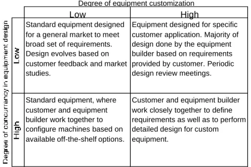
Equipment design (ED) may be thought of as a common design activity carried out simultaneously by companies that purchase the equipment and by companies that manufacture the equipment. Depending on the production system requirements of the purchasing company (i.e. customer), equipment design can fall into one of four categories of design relationships shown in Figure 2. The degree of equipment customization reflects the uniqueness of product and production system requirements and whether there exists a standard piece of equipment that a company may readily purchase for its needs. Concurrency indicates the extent to which the customer and equipment builder jointly design a piece of equipment. Concurrency in equipment design also reflects the communication of requirements and their inclusion into a given design.
For example, a standard machine will not require much concurrent design effort with any specific customer because it is meant to satisfy the requirements of a broad set of customers. On the other hand, a greater amount of concurrent engineering is needed when a machine must fulfill a unique set of requirements.
Low High
Standard equipment designed for a general market to meet broad set of requirements. Design evolves based on customer feedback and market studies.
Equipment designed for specific customer application. Majority of design done by the equipment builder based on requirements provided by customer. Periodic design review meetings.
Standard equipment, where customer and equipment builder work together to configure machines based on available off-the-shelf options.
Customer and equipment builder work closely together to define requirements as well as to perform detailed design for custom
equipment.
Degree of equipment customization
Figure 2: Range of design activities between customer and equipment builder in terms of concurrency and customization.
The next two subsections describe methods applicable to the different categories of equipment design shown in Figure 2. The first approach which generates guidelines from the PSD framework is well suited to low levels of concurrency and relatively standard equipment. An example where this approach is applicable is in turnkey production system designs where the requirements are provided to the equipment builder in the form of a document or guidelines. Design review meetings may then be held periodically to ensure that requirements are understood and are correctly being satisfied by the equipment designers.
The second approach, is the direct application of Axiomatic Design to equipment design. This approach is particularly useful in areas where there is a high degree of equipment customization and hence a corresponding need for a high degree of concurrent engineering effort. In this case, concurrency is supported by following a common design methodology for both the production system and equipment.
3.1 Generation of guidelines from PSD Framework
The first approach to apply the PSD framework to aid in equipment design is in the generation of a set of guidelines that capture the high le vel requirements of the production system. This approach regards the design of equipment as a “black-box” activity to which requirements must be supplied. Such an approach is representative of cases where companies purchasing equipment simply provide specifications to the equipment builder and then leave all detailed design entirely to the expertise of the builder.
This approach to equipment design has been used [10] based on the PSD framework in the design of an actual production system. Extracting key FR-DP pairs and grouping them into various categories yields a design guideline document that can be provided to equipment builders.
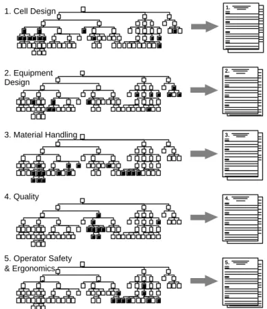
Figure 3 shows the shaded FRs-DPs that were extracted from the PSD decomposition hierarchy according to the categories: cell design, equipment design, material handling, quality, and operator safety and ergonomics. These categories were chosen because they reflect the different level of concurrent design activities that equipment builders participate in. For example, if the level of concurrency is high (production system designers working closely with equipment designers), then requirements from the cell design category will be particularly important because such vendors are system integrators as well as equipment designers. If the production system requires primarily standard equipment, then such a guideline approach is sufficient to select off-the-shelf equipment without the need for extensive concurrent design (upper left quadrant of Figure 2) 1. 5. 4. 3. 2. 2. Equipment Design 1. Cell Design 3. Material Handling 4. Quality 5. Operator Safety & Ergonomics
Figure 3: Generation of equipment guidelines from the Production System Design [10].
3.2 Axiomatic Design of Equipment based on PSD Decomposition
The previous section considered equipment design as a general activity to which production system requirements are provided, and therefore no conditions were placed on the design methodology employed by the equipment builder. This section presents the approach by which equipment builders may employ Axiomatic Design to arrive at designs that can better integrate production system requirements that have also been generated using AD. This section assumes that this approach is followed in cases where the degree of equipment customization is high or where standard equipment can be highly configured via available options (this corresponds to the two quadrants with a high degree of concurrency in Figure 2).
As a starting point for applying Axiomatic Design to equipment design and linking it to PSD requirements, a design decomposition was developed for a conventional CNC milling machine. The top level functional requirement is to mill a feature for a given part geometry. This FR is representative of the need a company may have that is purchasing a metal cutting machine. The six high level FR-DP pairs are shown in Figure 4.
FR11
Move tool relative to part DP11 Drive system FR12 Provide physical support for subsystems DP12 Machine structure FR13 Remove material DP13 Cutting tool FR14 Hold part DP14 Workholding system FR15
Hold cutting tool
DP15
Tooling system
FR16
Remove chips from machine
DP16
Chip removal system
Functional Domain Physical Domain
Figure 4: Top two levels of an Axiomatic Design decomposition for a CNC milling machine. For a company purchasing standard equipment, two common areas of customization are the work and tool holding system. For the general decomposition shown in Figure 4, this corresponds to FR-DP-14 and FR-DP-15 (workholding and tooling system branches). Figure 5 shows the third level of this decomposition and details of these branches for which the machine may be customized and those that are taken to be a given for a standard machine. Design examples for these two branches are given in Section 4.
Workholding Tool holding Chip Removal Drives Structure Cutting Tool
Equipment Design DP Hierarchy
Figure 5: Elements of standard equipment design that may be designed by Axiomatic Design.
3.2.2 Decomposition of Equipment DPs into sub-FRs
In Axiomatic Design, the process of generating sub-FRs from a higher level DP is termed decomposition (also referred to as “zig-zagging”). Though Tate [11] has developed guidelines for
general decomposition of DPs, this work addresses the source from which sub-FRs are generated, namely production system and product requirements. In linking an equipment design (ED) decomposition (such as that given in Figure 4) to a PSD decomposition, parent FR-DP pairs from the PSD provide views of higher level requirements and thus guide the desig ner in generating the sub-FRs (i.e. decomposing). The same set of FR-DP pairs that were selected from the PSD decomposition to generate the design guidelines in Section 3.1 are also used to decompose appropriate DPs in the equipment design DP hierarchy.
Another influence in the ED decomposition originates from product design (PD) requirements. The relationship between PSD and PD was developed [12] and described by means of a common process domain. Here, process variables are used to satisfy DPs (for both PSD and PD decompositions) and arise during process design. These process variables which can be traced back to FRs from either PSD or PD therefore contribute to additional sub-FRs in decomposition of equipment DPs.
Equation 1 describes the general decomposition (“
? ?
” read as “decomposes into”) of anequipment design parameter at a kth level into sub-FRs at a lower k+1 th level. The resulting set of
sub-FRs are comprised of those originating from the equipment design parameter DPkED and
those from the FR-DP pairs of the production system and of the product design (shown in Figure
6). Note that FR(PSD)kED?1 is read as the ED sub-FR derived from a PSD FR-DP pair.
?
1 1 1?
) ( , ) ( , ? ? ? ? k ED k ED k ED k ED FR FR PSD FR PD DP (1) k ED FR 1 ? k ED FR FR(PSD)kED?1 FR(PD)kED?1 k ED DP 1 ? k ED DP DP(PSD)kED?1 DP(PD)kED?1Equipment Design Decomposition
Functional Domain Physical Domain
k ED FR 1 ? k ED FR FR(PSD)kED?1 FR(PD)kED?1 k ED FR 1 ? k ED FR FR(PSD)kED?1 FR(PD)kED?1 k ED DP 1 ? k ED DP DP(PSD)kED?1 DP(PD)kED?1
Equipment Design Decomposition
Functional Domain Physical Domain
Figure 6: Decomposition of DPs in Equipment Design into sub-FRs guided by Production System Design (PSD) and Product Design (PD).
4. Equipment Design Example: Workholding and Direct Labor
Requirements
A study of two companies (A and B) was conducted to analyze differences in production system design approaches to design of equipment. A similar part made by both companies was chosen, and a common geometrical feature was used as the basis for process comparison. Each company’s design approach was examined using the general PSD and ED decomposit ions and studied based on how the equipment design met the specific production system requirement of reducing waste in direct labor.
Company A’s process consists of a single machine (Figure 7) that produces the required geometrical feature in one operation combining roughing and finishing machining passes. This specific machine has a dedicated operator to load and unload the machine. Company B’s process
(Figure 8) for producing the same geometrical feature consists of one machine to perform an initial roughing pass and a second to perform the finishing pass. Both of these machines have slower cycle times than the machine of Company A reflected in the lighter duty machine structures that can be used because roughing and finishing operations have been subdivided. Furthermore, at Company B a single operator loads and unloads parts on both machines and is also able to run other nearby machines not shown in the figure.
Roughing and finishing operations
Figure 7: Company A – single machine with combined roughing and finishing operations.
R F
Finishing
operation Roughingoperation
Figure 8: Company B – two machines separately performing roughing and finishing operations. To compare design approaches, the parent FR-DP-121 pair in Figure 9 - Reduce waste in direct labor was used to identify further PSD pairs that affect equipment design: [FR-DP]-D11, [FR-DP]-D12, and [FR-DP]-D23. The key difference between the companies in direct labor, reflected in how many machines the operators can handle is explained by Company B’s design of load/unload devices (Figure 10 – ED decomposition). For example, the PSD requirements to reduce tasks that tie operator to the machine and to enable the worker to operate more than one machine are satisfied by DP1435 and DP1436. These two DPs satisfy the sub-FRs 1435, 1436 which were decomposed by viewing the PSD FR-DP pairs 121-D11 and 121-D12. Together, these two DPs allow machines to be quickly loaded manually and automatically started with removal of a part from the machine and hence separate the human from the machine. Therefore, Company B used these two equipment DPs to eliminate operators waiting on machines and thus
hence to reduce waste in direct labor. In contrast, Company A did not incorporate these DPs into its workholding design and hence did not achieve effective use of its direct labor.
PSD Physical Domain FR-D1 Eliminate operators’ waiting on machines FR-D11 Reduce time operators spend on non-value added tasks at each station FR-D12 Enable worker to operate more than one machine / station FR-D2 Eliminate wasted motion of operators FR-D21 Minimize wasted motion of operators between stations FR-D22 Minimize wasted motion in operators’ work preparation FR-D23 Minimize wasted motion in operators’ work tasks FR121 Reduce waste in direct labor DP-D1 Human-Machine separation DP-D11 Machines & stations designed to run autonomously DP-D12 Workers trained to operate multiple stations DP-D2 Design of workstations / work-loops to facilitate operator tasks DP-D21 Machines / stations configured to reduce walking distance DP-D22 Standard tools / equipment located at each station (5S) DP-D23 Ergonomic interface between the worker, machine and fixture DP121 Elimination of non-value adding manual tasks PSD Functional Domain
FR143 Transfer part to/from workholding fixture FR1434 Detect presence of part FR1435 Detect removal of part FR1436 Ensure correct loading of part to fixture FR1431 Grasp part FR1432 Receive part from previous operation FR1433 Unload part in position/orient ation for next operation [FR-DP]121-D23 [FR-DP]121-D11 [FR-DP]121-D12 FR143 Transfer part to/from workholding fixture DP1434 Part sensor on gripper (or in-bound load position) DP1435 Part sensor on chute (or part nest) DP1436 Poka-yoke load sensor DP1431 Part gripper DP1432 Part load geometry features DP1433 Unload chute (part nest) Sub-FRs decomposed from Equipment DP Sub-FRs decomposed from PSD [FR-DP] pairs
Figure 10: Decomposition of equipment DPs into sub-FRs from PSD FR-DP pairs.
5. Equipment Design Application: Tooling system with quick
changeover capability
This example of equipment design focuses on the tool holding branch shown previously in Figure 5. The example is taken from a company whose PSD requirement is to have the ability to produce in small run sizes, FR-T12 (shown in the branch of the PSD decomposition in Figure 11) and had identified the need to have quick changeover capability in the tooling of its equipment, DP-T12. The sub-FR that decomposes from DP15 - Tooling system (see Figure 4) specifies the maximum
tool changeover time changeover
i
t allowable for the equipment being designed. (Design Equation 2).
The DP corresponding to this FR (originating from the PSD) is which is
?
i
disconnect i
t the sum of
the tool-to-machine disconnect times (total time to mount tooling onto a machine).
FR-T1 Reduce run size delay FR-T11 Knowledge of demanded product mix (part types and quantities)
FR-T12
Ability to produce in sufficiently small run sizes
DP-T1
Production of the desired mix and quantity during each demand interval DP-T11 Information flow from downstream customer DP-T12 Design quick changeover for material handling and equipment
Figure 11: PSD requirements [FR-DP]-T12 leading to equipment design tooling changeover sub-FR.
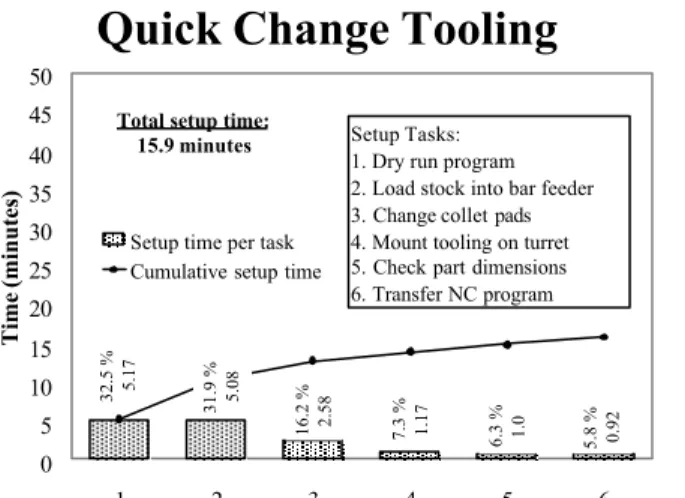
A study of the setup tasks (Figure 12) on a specific machine at the company revealed that the two largest components of setup time were the adjustment of tools and mounting tooling onto the machine (setup tasks 1 and 2). These two significant contributions to setup time can also be
observed by the coupling present in the FRs: toolholder
xyz
R? , toolholder xyz
F? , ntools, and changeover i
t (Equation
2). To reduce the total setup time, new tooling was designed that eliminated coupling between
toolholder xyz
R? and toolholder
xyz
F? (tool holder position and clamping force – Equation 3). Therefore, with
greater certainty in tool position, the need for adjustment of tools and workpiece was eliminated (Figure 13). ? ? ? ? ? ?? ? ? ? ? ? ? ? ? ? ?? ? ? ? ? ? ? ? ? ? ? ? ? ? ? ? ? ? ? ? ? ? ? ? ? ? ? ? ? ?? ? ? ? ? ? ? ? ? ? ?? ? ? ? ?
?
flow path turret coupling i disconnect i magazine clamps xyz locators xyz coolant i index i changeover i tools toolholder xyz toolholder xyz D D t N F R X O O O X O O X O X O O O O X X X X O O O X O O O O X O X X O O X X X X Q t t n F R ? ? ? ? (2)Equation 2: Current tool design exhibiting coupling in the design matrix.
1.9 % 0.92 2.7 % 1.33 4.0 % 2.0 5.7 % 2.83 66.8 % 33.0 18.9 % 9.33 0 5 10 15 20 25 30 35 40 45 50 1 2 3 4 5 6 Time (minutes)
Setup time per task Cumulative setup time Setup Tasks:
1. Adjustment of tools, workpiece
2. Mount tooling on turret 3. Load stock into bar feeder 4. Check part dimensions 5. Change collet pads 6. Transfer NC program
Total setup time: 49.4 minutes
Conventional Tooling
Figure 12: Setup data prior to implementing change.
? ? ? ? ? ?? ? ? ? ? ? ? ? ? ? ?? ? ? ? ? ? ? ? ? ? ? ? ? ? ? ? ? ? ? ? ? ? ? ? ? ? ? ? ? ?? ? ? ? ? ? ? ? ? ? ?? ? ? ? ?
?
flow path turret coupling i disconnect i magazine clamps xyz locators xyz coolant i index i changeover i tools toolholder xyz toolholder xyz D D t N F R X O O O X O O X O X O O O O X X X X O O O X O O O O O O X X O O O O O X Q t t n F R ? ? ? ? (3)5.8 % 0.92 6.3 % 1.0 7.3 % 1.17 16.2 % 2.58 32.5 % 5.17 31.9 % 5.08 0 5 10 15 20 25 30 35 40 45 50 1 2 3 4 5 6 Time (minutes)
Setup time per task Cumulative setup time
Setup Tasks: 1. Dry run program 2. Load stock into bar feeder 3. Change collet pads 4. Mount tooling on turret 5. Check part dimensions 6. Transfer NC program
Total setup time: 15.9 minutes
Quick Change Tooling
Figure 13: Setup data after implementing changes in tool designs.
6. Discussion
The design of equipment is an activity that must always be undertaken in the context of meeting production system requirements. Since equip ment builders provide a wide variety of machine design options to customers, different approaches are necessary to handle these cases while satisfying the requirements of the system. Two design approaches based on a PSD framework were presented that address the different categories of equipment customization and concurrent design. Though the first approach is effective in most turnkey forms of production system design, a more integrated approach is needed where there are greater levels of equipment customization. The second approach presented offers better understanding of interdependencies (to facilitate concurrency) amongst equipment and system requirements because a common design methodology (Axiomatic Design) is employed. Finally, two examples illustrated this second approach by decomposition of equipment DPs into sub-FRs guided by PSD requirements such as direct labor and tool changeover.
Acknowledgements
The authors gratefully acknowledge the sponsorship of Visteon Automotive Systems and United Electric Controls.
References
1. Wu, B., Manufacturing Systems Design and Analysis, Chapman and Hall, 1992.
2. Gershwin, S.B., Manufacturing Systems Engineering, Prentice Hall, 1994.
3. Hitomi, K., Manufacturing Systems Engineering, Taylor and Francis, 1996.
4. Wu, B., “Object-oriented systems analysis and definition of manufacturing operations”,
5. Mize, J.H., Bhuskute, H.C., Pratt, D.B., Kamath, M., “Modelling of Integrated Manufacturing
Systems using an Object-Oriented Approach”, Vol. 24, No. 3, IIE Transactions, July 1992, pp.
14-26.
6. Oliver, D.W., Kelliher, T.P., Keegan, J.G., Engineering Complex Systems with Models and
Objects, McGraw-Hill, 1997.
7. Suh, N. P., The Principles of Design, Oxford University Press, 1990.
8. Cochran, D. S., The Design and Control of Manufacturing Systems, Ph.D. Thesis, Auburn
University, 1994.
9. Suh, N.P., Cochran, D.S., Lima, P.C., “Manufacturing System Design”, in 48th General
Assembly of CIRP, Annals of the CIRP, Vol.47/2, 1998, pp. 627-639.
10. Arinez, J.F., Collins, M.T., Cochran, D.S., Uhl, M.D., Cook, P., “Design of an Automotive
Compressor Production System Using Lean Manufacturing Design Guidelines”, in Proceedings
of the 1999 SAE International Automotive Manufacturing Conference, IAM99-34, May 11-13, 1999, Detroit, U.S.A.
11. Tate, D., A Roadmap for Decomposition: Activities, Theories, and Tools for System Design,
Ph.D. Thesis, Massachusetts Institute of Technology, 1999.
12. Arinez, J.F., Cochran, D.S., “Integration of Product Design and Production System Design”, in Proceedings of the International CIRP Design Seminar, Enschede, The Netherlands, March 24-26, 1999, pp. 99-108.
![Figure 1: PSD Decomposition; first three levels [9]](https://thumb-us.123doks.com/thumbv2/123dok_us/9412535.2423191/3.918.131.782.101.826/figure-psd-decomposition-levels.webp)


![Figure 11: PSD requirements [FR-DP]-T12 leading to equipment design tooling changeover sub- sub-FR](https://thumb-us.123doks.com/thumbv2/123dok_us/9412535.2423191/11.918.304.611.359.480/figure-psd-requirements-leading-equipment-design-tooling-changeover.webp)