http://www.sciencepublishinggroup.com/j/ijmea doi: 10.11648/j.ijmea.s.2017050401.15
ISSN: 2330-023X (Print); ISSN: 2330-0248 (Online)
Integration of a Multi-scale Homogenization Model into
Finite Element Software for Predicting Mechanical
Properties of Bulk Moulding Compound (BMC) Composite
Le Thi Tuyet Nhung
1, *, Vu Dinh Quy
1, Vu Quoc Huy
1, Phan Truc Dien
21Department of Aeronautical & Space Engineering, School of Transportation Engineering,Hanoi University of Science and Technology,
Hanoi, Viet Nam
2Department of Aerospace Engineering, Faculty of Transport Engineering, Ho Chi Minh City University of Technology, Ho Chi Minh City,
Viet Nam
Email address:
[email protected] (Le T. T. Nhung)
*Corresponding author
To cite this article:
Le Thi Tuyet Nhung, Vu Dinh Quy, Vu Quoc Huy, Phan Truc Dien. Integration of a Multi-scale Homogenization Model into Finite Element Software for Predicting Mechanical Properties of Bulk Moulding Compound (BMC) Composite. International Journal of Mechanical Engineering and Applications. Special Issue: Special Issue: Academic Research for Multidisciplinary. Vol. 5, No. 4-1, 2017, pp. 26-32. doi: 10.11648/j.ijmea.s.2017050401.15
Received: May 26, 2017; Accepted: June 1, 2017; Published: July 17, 2017
Abstract:
Bulk Moulding Compound (BMC) is a short fiber composite with random orientation, used in many industrial sectors such as automotive, electrical,... Design and optimization of composite structures made of BMC meet difficulties due to the nature of this material and thus have not been integrated in the finite element software. This paper introduces a method to build and integrate a new computational model into finite element software (ABAQUS). The chosen model is a multi-scale homogenization model, which helps to calculate mechanical properties of composite materials by using the properties of the components and orientation tensor. This integration can be applied for prediction of composite properties on many kinds of materials, reducing time and cost for suppliers when it comes to optimization of mechanical properties.Keywords:
BMC, Short Fiber Composite, Multi-scale Homogenization, Abaqus Plugin1. Introduction
With many interesting properties such as high specific strength, high corrosion and fatigue resistance, composite materials is widespread used in both civil and military applications. Mechanical properties of composite material depend strongly on its fiber orientation. Laminate composite structures with long fiber pre-oriented along some directions are widely used in aerospace. Thus, the precdiction of mechanical properties of laminate composie structure was intergrated in many finite element software such as Abaqus, ANSYS.
In automotive sector, short fiber composite with random orientation is used due to its low-cost price and simple manufacturing technology. However, the predicion of mechanical properties of short-fiber composite with random orientation is more complex and has not been integrated in
the finite element softwares.
Nowadays, predicting mechanical behavior of composite is important for employing into real products. It includes many processes, which is supported by many softwares. Hence, integrating a new computational model to into a finite element software is more and more widely applied in the world. This helps people to use the tools most effectively and minimizing the timeconsumed.
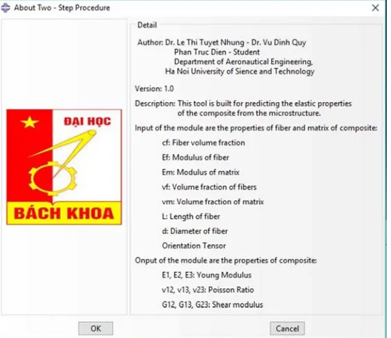
In this paper, a multi-scale homogenization model is built to calculate the mechanical properties of BMC composite by using the two-step homogenization procedure [1], which stands on a classic approach in elasticity of T. Mori & K. Tanaka [2]. The BMC is considered an orthotropic materials. The calculated results are then compared with expermental results of two different materials carried out by N. Le et al. [3] to validate the model.
to predict mechanical behaviours of short fiber composite. A program written in Python programming language is integrated in ABAQUS as a plug-in via ABAQUS GUI Toolkit [4].
2. Experimental Characterization of
BMC Composite
2.1. Material
a) Injected plate
b) Xmold
Figure 1. Two short fiber BMC composite samples: a) Injected plate; b) Xmold.
Two types of short fiber BMC composite are consisdered: Injected plate and Xmold. Both types consist of 20% of E-glass fibers (6 mm long and 14 µm diameter) and 80% of polyester resin in weight. The fiber were randomly distributed before injection. The Young’s modulus, Poisson’s ratio of the matrix and the fiber are equal to 6.5 GPa, 0.27 and 74 GPa, 0.28, respectively. The samples of 100mm x 100 mm were cut from four corner of the Xmold and injected plate to do the microstructure test. Then five small samples were extracted from the square sample for the tensile test.
2.2. Orientation Tensor
In composite, the microstructure plays an important role in determining the physical and mechanical properties. According to several authors [1, 2, 5], among different parameters, fiber orientation is the most important. In
general, there are two methods for measuring the orientation tensor: Ultrasonic method and Image Analysis method.
In the case of composites reinforced with short fibers, considering that they are of circular section, the intersection of a cutting plane (X, Y, Z) with a fiber forms an ellipse with major radius a and minor radius b. (Figure 2)
The software image analysis, Ellix [1], identifies each fiber as an ellipse and automatically determines the characteristics of the ellipse, it determinesthe coordinates (xc, yc) of its
center, its radius a and b and its angle Φ in the cutting plane, compared to a reference direction. The angle θ is determined by the relationship:
(1)
Figure 2. Intersection of a fiber with a cutting plan.
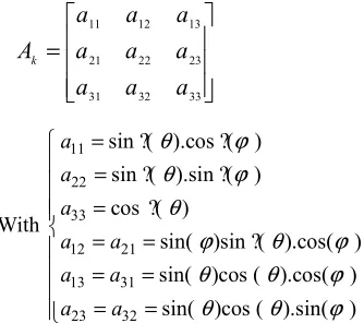
When a single fiber k is orientation (θk, Φk), we can infer
the orientation tensor of the fiber k [6, 7]:
=
33 32 31 23 22 21 13 12 11a
a
a
a
a
a
a
a
a
A
k (2)With 11 22 33 12 21 13 31 23 32
sin ?( ).cos ?( ) sin ?( ).sin ?( ) cos ?( )
sin( )sin ?( ).cos( ) sin( )cos ( ).cos( )
sin( )cos ( ).sin( ) a a a a a a a a a θ ϕ θ ϕ θ ϕ θ ϕ θ θ ϕ θ θ ϕ = = = = = = = = =
In the case of BMC composites, Image Analysis method is used by N. Le et al. [3] to obtain the orientation distribution of fibers in the form of orientation tensor. These results confirm that the preferred orientation of fibers is in the direction of flow, BMC material is highlyanisotropic By averaging the tensor orientation in 16 layers of thickness, the 3D orientation tensor in the thickness of injected plate (I-Pl) and Xmold sample are:
20
0.551 0.076 0.025 0.076 0.416 0.004 0.025 0.001 0.032
F I Pl
A − −
20
0.874 0.032 0.020 0.032 0.104 0.004
0.020 0.004 0.022
F Xmold A − − = − (4)
2.3. Tensile Test in Macroscopic Scale
Tensile tests were carried out to obtain mechanical properties of the BMC composites. The result shows a significant difference of behavior between the transverse direction and the longitudinal direction, which is consistent with the fiber’s orientation distribution. The distribution of fibers in Xmold sample is less anarchic than those in the injected plate. Therefore, the value of the anisotropic ratio (E2c/E1c) of Xmold is larger than injected plate.
Table 1. Mechanical properties of two types of BMC composite: Injected Plate and Xmold sample [8].
Parameter 20F-Xmold 20F-I-Plate E1 (GPa) 10.76 ± 0.67 9.75 ± 0.82 E2 (GPa) 9.24 ± 0.45 9.15 ± 0.52
E2/E1 0.86 0.95
3. Homogenization Model
3.1. Principle of ModelFor the composite containing fibers with an orientation distribution, it is impossible to predict the effective elastic properties using a two-step homogenization procedure. In this case, the model is considered as a first step for a fictitious material where all fibers are aligned and the unidirectional composite properties are calculated by Mori-Tanaka model [2]. For example, stiffness tensors are calculated by the following formula:
(
)
:UD MT
m f f m
C =C +c C −C A (5) Where f and m refer to the fibers and the matrix, respectively, with stiffness tensors Cf and Cm; cf is the volume fraction. The
strain concentration tensor in the fibers AMT that the model deduces is obtained from Eshelby tensor E which depends on the fiber aspect ratio and the matrix elastic constants.
(
)
11 MT
f f
A =A −c I+c A− (6)
With
( )
1(
)
1f m
m
A=I+E C − C −C − (7) where I is the identity tensor.
In the second step, as in the method of Advani and Turker [7], the unidirectional properties are weighted by the orientation distribution function ψ(θ,φ).
( ) ( )
, ,UD
C C θ ϕ ψ θ ϕ d Ω
=
∫
Ω (8)Where Ω is the unit sphere, with:
sin
dΩ = θ θ ϕd d (9)
( )
θ ϕ, d 1Ω
Ψ Ω =
∫
(10)The prediction of mechanical behavior in the elastic phase is performed using the orientation tensor. Therefore, the stiffness tensor can be recalculated by the following equation:
(
)
(
)
(
)
1 2 3 4 5ijkl ijkl ij kl kl ij
ik jl il jk jl ik jk il
ij kl ik jl il jk
C C C a C a a
C a a a a
C C δ δ δ δ δ δ δ δ δ δ δ δ = = + + + + + + + + + (11)
Where δij is the Kronecker symbol and five constants
C1,..., C5 are calculated from the stiffness tensor CUD; aij and
aijkl are the second-order and the fourth-order orientation
tensors.
Both of second-order and fourth-order orientation is needed for this method but the fourth-order one is unknown. In this case, this orientation tensor can be calculated from the second-order by using several closure approximations. They are given respectively by:
The linear equation, which is exact for a completely isotropic distribution of fiber orientations:
(
)
(
)
1 35 1 7 Lijkl ij kl ik jl il jk
ij kl ik jl il jk kl ij jl ik jk il
a
a a a a a a
δ δ δ δ δ δ
δ δ δ δ δ δ
= − + +
+ + + + + +
(12)
The quadratic equation, which is exact for aligned fibers
.
Qij kl ijkl
a
=
a a
(13)The hybrid equation, which is intermediate between the linear and the quadratic:
(
1
)
QH L
ijkl ijkl ijkl ijkl
a
=
a
= −
f a
+
f a
(14)With
( )
1 27 det
ijf
= −
a
(15)The model was built in Matlab software to calculate the stiffness tensor of composite using the theory in this paper.
3.2. Results and Discussions
In table 2, for the first case, all fibers are aligned in direction 1, and the Young’s modulus of this direction is equal to 15.71 GPa. Because of orthotropic material, the value of E1c is the same with E2c. In the second case, all
fibers are aligned in the second direction. We found a similar result compared with the first case. Finally, the direction in the third case is symmetric between first and second directions. So, the E1c and E2c values are identical. In
conclusion, the model is validated for unidirectional composites. Basically, the maximum error of 7.5% between these results and the simulation results of N. Le et al. [3] is
accepted.
Then, we apply this model for predicting the material’s properties of two forms of BMC composite: 20F-Plate-I and 20F-Xmold. Results in Table 3 show that the Young modulus in the longitudinal direction of 20X – Xmold is maximum (11.8 GPa). An error of 12.6% of this simulation is little significant. One of the causes for this error may come from the avarage of orientation tensor. In case of 20F-I-Plate, the difference between simulation and experiment is less than 5.7%. Finally, this proves that our model is accepted for both types of BMC.
Table 2. Validation of the model for simple cases.
Unidirectional – direction 1 Unidirectional – direction 2 Unidirectional – direction 3
20 0
1 0 0 0 0 0 0 0 0
F
A −
=
20 90
0 0 0 0 1 0 0 0 0
F
A −
=
20 45
0.5 0.5 0 0.5 0.5 0
0 0 0
F
A −
=
E1c = 15.71 GPa (Error: 7.5%) E1c = 8.45 GPa (Error: 4.1%) E1c = 8.49 GPa (Error: 1.7%) E2c = 8.45 GPa (Error: 4.1%) E2c = 15.71 GPa (Error: 7.5%) E2c = 8.49 GPa (Error: 1.7%) E3c = 8.45 GPa (Error: 4.1%) E3c = 8.45 GPa (Error: 4.1%) E3c = 8.45 GPa (Error: 4.1%)
Table 3. Comparison between Simulation and Experiment of the BMC elastics properties.
20F - Xmold 20F – I – Plate
Simulation Experiment Error (%) Simulation Experiment Error (%) E1c (GPa) 11.18 10.76±0.67 3.9 9.41 9.75±0.82 3.5 E2c (GPa) 8.07 9.24±0.45 12.6 8.63 9.15±0.52 5.7
E3c (GPa) 8.01 8.30
4. Integrating Multi-scale
Homogenization Model into ABAQUS
Normally, two methods are used to integrate our model into ABAQUS: Writing User Subroutine and Writing Plugin[9]. In this section, we will present the method to integrate the multi-scale homogenization into ABAQUS by
Writing Plugin.
Figure 3. Basic view of the interface GUI within ABAQUS /CAE.
The main window of the interface contains many textboxes for the user to insert the parameters of our model.
Figure 4. Input parameters.
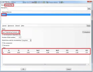
Then, Abaqus will solve and create a new user-defined material automatically.
5. Testing of Integrated Model
Two simulations of composite plate BMC-Injected (0.5m x 0.5m x 0.005m) solicited by the same load and boundary conditions will be presented. A concentrated force of 500N was applied in the center of plate. Four edges of the plate were clamped.
In the first case, we use the material from the experiment, shear modules were calculated from Young modules and Poison’s ratio [10], in the second case we use the material from the integrated model (Table 4). The results obtained by two simulations’ will be compared to validate this model.
Table 4. Material’s properties of two simulations.
a) Experiment b) Integrated model
Young’s Module (GPa)
E1 = 9.75 Ef = 72 E2 = 9.15 Em = 6.5 E3 = 9.15
Poison’s ratio v = 0.28 vf = 0.28, vm=0.27 Orientation aij= A20F-I-Pl
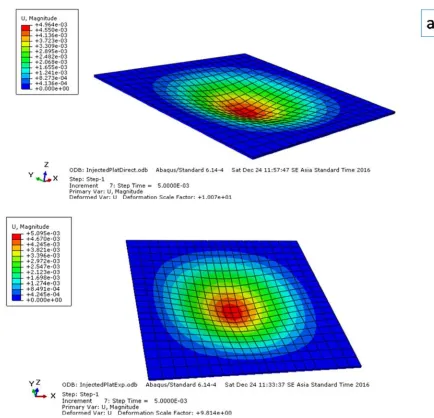
The Figure 6 shows the distribution of displacements in two simulations. The maximum displacement was founded in the same position, it is equal to 5.09 mm in the case a and 4.96 mm in the case b.
Figure 6. Distribution of displacement (mm) of two simulation cases: a. Input parameters from experiment; b. Input parameters calculated from the integrated model.
Table 5. Comparison of two simulations.
Results Experiment Integrated model
Error (%) Von-Mise Stress (MPa) 22.19 22.71 2.3 Displacement (mm) 5.095 4.964 2.6
The Table 5 shows the correlation between the two
6. Conclusion
In this paper a homogenization model based on a two-step homogenization procedure was integrated into ABAQUS FEA software for predicting mechanical behaviors of short fiber composite. The comparison of calculated and experimental results shown a good agreement. This integration is helpful for users to calculate mechanical properties of many kinds of materials and to create them in ABAQUS FEA software quickly. Moreover, this plugin is simple and easy to use. This tool allows us to optimize the microstructure of the BMC.
Acknowledgments
This work was supported by Hanoi University of Science and Technology. Code subject: T2016-PC-018.
References
[1] Dray D., Prédiction des propriétés thermo élastiques d’un composite injecte et charge de fibres courtes, LIM – ENSAM. 2006, Paris.
[2] Mori T., Tanaka, Average stress in matrix and average elastic energy of materials with misfitting inclusion, K. Acta Metall., 21, pp. 571-574, 1973.
[3] N. Le, K. Derrien, D. Baptiste, J. Fitoussi, Composites BMC injectés: analyse et modélisation multi-échelles du comportement endommageable, PIMM-ENSAM, Paris, 2011. [4] ABAQUS 6.10 GUI Toolkit User’s Manual, Dassault
Systèmes.
[5] E. Le Pen, D. Baptiste, Prediction of the fatigue-damaged behavior of Al/Al2O3 composites bye a micro-macro
approach, Composites Science and Technology, Volume 61, Issue 15, November-December 2001, Pages 2317-2326. [6] Teyssier S., Analyse globale de l'orientation dans un BMC et
relation avec les propriétés mécaniques, Université de Savoie, LMOPS, UMR CNRS 5041, Chambéry, 2002.
[7] SG. Advani and C. L. Tucker III, The use of tensors to describe and predict fiber orientation in short fiber composites, J. Rheol., 31, pp. 751-784, 1987.
[8] Thi Tuyet Nhung LE, The Hoang NGUYEN (2013). Multi-scale homogenization model for predicting the mechanical behavior of composite. Journal for Research and Technology of HCM City University of Transport, Số 7+8, 9/2013, pp. 175-178.
[9] Phan Truc Dien, Intergrating multi-scale homogenization model into element software, thesis, 2014, HCM City University, Hồ Chí Minh City , 2014.
[10] Autar K. Kaw, Mechanics of Composite Materials, 2ed, Taylor & Francis Group, LLC, 2006.
Biography
Thi Tuyet Nhung Le (1983, Vietnam) PhD
in Mechanics & Materials (2012, Predicting Behaviour law of BMC composite using multi-scale homogenization method) – Arts et Metiers Paristech (ENSAM-Paris), Engineer in Aeronautics of ENSMA-Poitiers, France. Lecturer and Researcher at Department of Aerospace Engineering, Ho Chi Minh City University of Technology, Vietnam. Research experience: Composite material, Aero-elasticity, Multi-scales modelling, Damage behaviour, Fatigue, Fracture mechanics, Computational Structure Dynamics. About 5 publications in scientific and professional papers and about 5 papers on conference proceedings.
Dinh Quy Vu (1983, Vietnam) PhD in
Materials and Structure Mechanics (2011, Thermo-oxydation of polymer matrix composite) - Ecole Nationale Supérieure de Mécanique et d’Aérotechnique (ENSMA), Univervité de Poitiers, France. Senior Lecturer and Researcher at Department of Aeronautical and Space Engineering, Hanoi University of Science and Technology (HUST), Vietnam. Research experience: Aero-elasticity, Structure Mechanics, Composite Material, FSI Simulation, Micro-Wind Energy. About 5 publications in scientific and professional papers and about 15 papers on conference proceedings.
Quoc-Huy Vu (1982, Vietnam) PhD in
Structure Mechanics, (2009) - Ecole Nationale Supérieure de Mécanique et d’Aérotechnique (ENSMA), University of Poitiers, France. Senior Lecturer and Researcher at Department of Aerospace Engineering, Hanoi University of Science and Technology, Vietnam. Research experience: Fatigue multiaxial, Damage modelling, Numerical simulation, Composite material, Aero-elasticity. Head of the Department of Aerospace Engineering at Hanoi University of Science and Technology. About 5 publications in scientific and professional papers and about 15 papers on conference proceedings.
Phan Truc Dien (1991, Vietnam) Engineer
![Table 1. Mechanical properties of two types of BMC composite: Injected Plate and Xmold sample [8]](https://thumb-us.123doks.com/thumbv2/123dok_us/8461507.1708587/3.595.38.292.284.326/table-mechanical-properties-composite-injected-plate-xmold-sample.webp)