Deterministic Models of the Physical Layer through Signal
Simulation
Daniel Maier
[email protected]
steffen.moser@uni-
Steffen Moser
ulm.de
Frank Slomka
[email protected]
Institute of Embedded Systems/Real-Time SystemsFaculty of Engineering and Computer Science and Psychology Ulm University
ABSTRACT
Current wireless network simulators provide very detailed and deterministic models of the network protocol layers, whereas rather simple and stochastic models, based on the signal-to-noise ratio, are used for the simulation of the phys-ical layer. Although this approach can be sufficient to study the behavior of different upper layer protocol variations, it prevents an easy alteration of the physical layer because a stochastic abstraction of the physical layer must be pro-vided in advance. In particular, the simulation of distributed systems with physical layers that are designed to have sev-eral senders transmitting signals at the same time intention-ally, is hardly possible with current approaches. A further problem of stochastic physical layer simulations is the fact that the radio channel’s influence must also be carried out stochastically, which limits the advantage of accurate ray-optical channel models. We present a novel approach for the accurate simulation of the physical layer by utilizing ex-isting software-defined radio implementations to create sig-nals, to calculate interference and to decode signals. This technique enables us to simulate wireless networks holisti-cally and, furthermore, we can fully exploit the possibilities of available ray-optical channel models.
Categories and Subject Descriptors
C.2.1 [Computer-Communication Networks]: Wireless communication; I.6.5 [Simulation and Modeling]: Model Development
General Terms
Algorithms, Experimentation, Measurement
Keywords
Wireless Networks, Simulation, Physical Layer, Signal Sim-ulation, Software-defined Radio
1.
INTRODUCTION
Current wireless network simulators provide very detailed deterministic models of the network protocol layers. The models simulate the flow of data packets from a transmitter node to one or more receiver nodes. For example, effects like queuing, retransmitting, acknowledging and routing of packets according to the simulated protocol are considered. However, the physical layer (PHY), which is the interface between analog signals on the one hand and data packets on the other hand, is simplified tremendously in state-of-the-art network simulators.
While in fact being a rather complex subsystem of a net-work communication system, the PHY layer is typically sim-ulated stochastically by using a bit error rate (BER) based model. The BER is derived from the signal-to-noise ratio (SNR) or—in more advanced simulators—from the signal-to-interference-plus-noise ratio (SINR). The models are put down to the assumption that interference between different signals caused by nodes, which transmit in a time-overlap-ping way, is basically a condition which hinder the reception of a signal.
While this rather simple approach might be acceptable for collision avoiding medium access methods (MAC) like for ex-ample CSMA/CA (Carrier Sense Multiple Access/Collision Avoidance) as used in the IEEE 802.11 protocol family, it shows the following drawbacks and makes various simulation studies impossible:
1. The simulation of communication systems based on MAC protocols like CDMA (Code Division Multiple Access) is—by principle—infeasible. CDMA is a MAC mechanism which explicitly allows different nodes to transmit signals at the same time and at the same frequency by using a spread spectrum approach and a node-specific code. A simplified decision between successful packet reception and collision based on the SNR value is not sufficient because decoding the pack-ets from the received superposition of signals is the part of interest, especially under time-variant channel conditions.
Using CDMA looks promising against the background of real-time communication [8]. In contrast to sys-tems based on CSMA/CA, real-time constraints can be guaranteed by CDMA. Especially in asynchronous
SIMUTOOLS 2015, August 24-26, Athens, Greece Copyright © 2015 ICST
CDMA systems network nodes are allowed to transmit without any channel listening and waiting.
2. A very similar problem occurs if network simulations are used to study modern communication approaches like multiple-input, multiple-output (MIMO) systems or even multi-user MIMO (MU-MIMO). MIMO is, for example, used in IEEE 802.11n, MU-MIMO in IEEE 802.11ac. To study MIMO or MU-MIMO communi-cation systems in a realistic way, it is also necessary to simulate the decoding of packets from a superpo-sition of signals which overlap in time and frequency domain. To the best of our knowledge, there is no sim-ple and general stochastic approach which decides the receptability of packets in a MU-MIMO system, espe-cially in a complex scenario with a time-variant and delay-spreading channel.
3. In network simulations, the SNR or SINR values are calculated using a channel model. While the channel models used in state-of-the-art simulations are often rather simple combinations of stochastic fading mod-els and distance-based path-loss modmod-els, which deter-mine the SNR derived from Friis’ transmission equa-tion [1], there are also more sophisticated models avail-able. It has been shown that in highly dynamic net-work topologies, like for example vehicular ad-hoc-networks (VANET), simple distance-based path-loss models do not offer the required accuracy [17]. For this reason, ray-optical channel models have been devel-oped which calculate a delay spread of a signal based on the three-dimensional environment. For example, in vehicular ad-hoc networks buildings, vehicles and the terrain roughness are considered by ray-optical ap-proaches. The resulting delay spread shows the tempo-ral diversification and energy distribution of different multi-path components of a signal. To link ray-optical channel models to current wireless network simulators, the delay spread needs to be reduced to a scalar SNR value, effectively discarding most of its information.
4. Stochastic approaches as used in PHY models of state-of-the-art network simulators are based on probabil-ity distributions. They have been derived from large-scale measurement campaigns. While all established network simulators bring their stochastic models for the common protocols like IEEE 802.11, this approach makes it hard to exchange or modify the PHY layer as the stochastic model would not be available in this case. For this reason, optimizations at the PHY layer are rarely part of the typical network simulation stud-ies whereas, for example, in VANETs a lot of optimiza-tions at the routing protocols are done. The simplified approach used in network simulators prevents the PHY layer to be a fully exchangeable and optimizable part of a communication system’s design space.
These drawbacks can be summarized as follows: Extensive simplifications of the PHY layer in state-of-the-art network simulators prohibit a detailed studying and optimization of the PHY layer itself in the context of the entire communica-tion stack. In the last years there has been a lot of progress in PHY layer development, e.g. communication systems like
IEEE 802.11ac, W-CDMA or LTE contain quite sophisti-cated approaches compared to, for example, IEEE 802.11a or IEEE 802.11p. The last-mentioned standard is proposed for communication in VANETs, but especially in scenarios with a fast-changing topology and with highly time-variant channel conditions, a co-simulation of channel, PHY layer and the network protocol’s upper layers would be very ben-eficial. Although our approach addresses various kinds of networks, we take VANETs as an exemplary application. Due to the above mentioned properties, VANETs are quite challenging. With IEEE 802.11p being in the process of standardization for VANETs, it is important to be able to investigate the outcome of different options and enhance-ments in the PHY layer.
There have been some attempts to fix the disregard of the physical layer in network simulators. However they are ei-ther hardware-based and ei-therefore tied to the existence of hardware prototypes, or they consist of an implementation of a specific protocol. To the best of our knowledge there is no general, software-based simulator extension which satis-fies all of the above stated needs.
In this paper, we present a new model for the simulation of the physical layer. Our generic approach takes advantage of the emerge of software-defined radios (SDR) and therefore of the availability of ready-made and publicly available imple-mentations of wireless communication protocols including the PHY layer. We implemented a prototype implementa-tion which uses GNU Radio building blocks for generaimplementa-tion and decoding of baseband IEEE 802.11p signals. The im-plemented signal simulation was integrated into the Veins VANET simulator to achieve a co-simulation of the network protocol and the signal processing. We also compared our approach with the standard PHY that comes with Veins.
We can show two important outcomes: Firstly, as expected, stochastic modeling is a valid approximation for collision-avoiding PHYs like CSMA/CA. Secondly, our complete PHY implementation works well and delivers reasonable results.
The remainder of this paper is organized as follows: Sec-tion 2 introduces related work in the field of accurate PHY layer simulation. In section 3 we firstly give an outline of our work followed by an introduction of required techniques. We present the challenges of our approach and how to han-dle them and eventually present a detailed view how our implemented prototype works. In section 4 we show the results of a comparison of our deterministic physical layer with a stochastic model and in section 5 we summarize our contribution and the results.
2.
RELATED WORK
In VANET research, the use of more accurate radio channel models and the explicit simulation of the PHY layer have received noticeable attention, as the limitations of the too simplistic models as introduced in the first section are obvi-ous.
The properties of radio channels can be simulated most ac-curately by solving Maxwell or Helmholtz equations given the presumption that there is a environment model of the simulation scenario. Solving these wave equations requires a huge amount of computation power. Especially in highly dy-namic channel conditions as they are common to VANETs, the effort of computation is usually too high as the chan-nel conditions have to be recalculated in each simulation step. For this reason approaches based on geometrical op-tics are used as an approximation: Radio propagation is con-sidered as light which propagates along rays. Typical wave effects like edge diffraction are added to the model. This ap-proximation still delivers quite precise results as shown by Maurer [6], Moser et al. [7] and Schmitz et al. [11, 12, 13]. Further approximative approaches published by Sommer et al. [15] distinguish between signal transmission in a line-of-sight (LOS) versus in a non-line-of-line-of-sight (NLOS) condition. Based on this property, appropriate stochastic PHY models are chosen by the simulator.
Both, the wave-based and the ray-optical models typically calculate or approximate a radio channel’s impulse response, i.e. a distribution of transmission power over time. Schu-macher et al. [14] described a method to derive an SNR value from real-world geometric data, but this discards im-portant information, like multi-path propagation and time variant changes in received power. To actually exploit this information, an explicit and deterministic PHY simulation is required. In the remainder of this section we present im-portant contributions in the field of deterministic PHY sim-ulation.
A hardware-based channel emulator has been developed by Judd and Steenkiste [5] and has received a lot of attention. By connecting a cable between the antenna ports of real wireless hardware (e.g. laptops) and their FPGA-based sys-tem, they can emulate the channel’s effects on the radio propagation. The system supports dynamic movement of the simulated nodes. Interfering signals are superimposed. They use a simple path-loss model as a channel model, but the authors point out that simulation of the 3D environment is possible by implementing, for example, a ray-tracing based model on the FPGA. While the built prototype consists of only three nodes, the system can emulate up to 50 nodes us-ing a sus-ingle FPGA. This number can be further increased by adding another FPGA. This is a very interesting and flexible approach for accurate physical layer consideration in wire-less network simulations: Real network interface hardware is used for signal processing. At the same time this is one of the major downsides of this concept: It obviously depends on hardware implementations of the protocol which is about to be studied. Wireless network interfaces must be already available which does not only rise financial burdens—the au-thors estimate a price of several hundred USD per node to be simulated—, but is also hard to accomplish in an early design phase.
Papanastasiou et al. have implemented the PHY of IEEE 802.11p using C++ [9]. Their contribution is a drop-in re-placement for the previous PHY model which has been built-in built-into the ns-3 network simulator. They have used IT++, a signal processing and communications library, to create sig-nals as they are transmitted by network nodes. Using chan-nel models which are also provided by IT++, they added the influence of the channel between sender and receiver. They have mapped the reception of a signal to four events: (1) begin of the preamble, (2) begin of the frame header, (3) begin of the frame payload and (4) end of frame payload. At event 1 the signal is added to the node’s list of current signals. All following signal processing steps are performed on the mix of overlapping signals and thermal noise: At event 2 the receiver tries to detect and sync to the preamble. Only if this succeeds, the subsequent steps are performed. At event 3 the header is decoded. Finally at event 4, the payload is decoded and a decision whether the reception of the signal was successful is made. To verify the correct-ness of their implementation, the authors compared signals created by their software with examples taken from the an-nex of the IEEE 802.11 standard. They have conducted data about the performance of their PHY by comparing it with the vanilla PHY provided by ns-3 and with the above-mentioned hardware-based signal emulation that connects wireless network interfaces to a wired channel model [5].
While there has been great preceding contributions in the field of physical layer simulation, to our knowledge there exists no generic approach for the accurate simulation of the physical layer.
3.
SIGNAL SIMULATION: A
DETERMIN-ISTIC MODEL OF THE PHYSICAL
LAYER
A deterministic model replicates the behavior of a system in a non-random way by simulating the process in the system.
Setting up a deterministic simulation of a physical layer im-plies that the following aspects are considered:
• The physical layer generates analog signals based on given digital data packets. This process has to be sim-ulated.
• The physical layer reconstructs digital data packets from received analog signals. This process has also to be simulated.
• The radio channel between transmitter and receiver alters the signal. Multi-path propagation can cause interference.
• Additional interference can occur due to transmitters which are transmitting at the same time.
• Additional thermal noise can occur and alter the sig-nal.
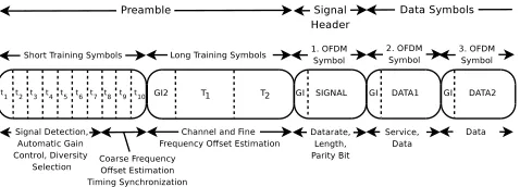
Figure 1: Structure of an OFDM frame.
In order to implement the signal simulation, we are going to identify the required components by looking at real-world examples of communication systems.
The process which is performed by a transmitter is relatively simple. It has a to implement a set of rules to map given digital bit patterns to sequences of signal values. It will be discussed later.
The process which is performed by a receiver is more com-plex. It might, for example, use direct conversion to im-plement down-conversion and analog-to-digital conversion. The output is a complex baseband signal which will be pro-cessed further. Figure 1 shows the example of an Orthogonal Frequency-Division Multiplexing (OFDM) frame. OFDM is used by many modern communication systems. An in-depth understanding about the internals of OFDM is not required for this explanation. A receiver will firstly try to detect the preamble and to synchronize itself to the signal. In the next step, it will decode the signal field in the first OFDM symbol which tells the receiver, how the rest of the frame will have to be decoded. After the last data symbol has been received, it verifies the checksum and can start parsing the payload. Within a simulation, the model represents the relevant be-havior of a process. The bebe-havior of a receiver’s physical layer depends on the received signals, therefore it is neces-sary to map what is happening at the receiver’s antenna. Signals received at the same time interfere with each other. The interferences depend on involved signals and the posi-tion of the receiver and hence the resulting mix of signals cannot be estimated but has to be calculated.
In order to calculate the mix of signals, the involved individ-ual signals have to be calculated in the first place. For this step, a transmitter that can calculate a valid signal from the bit stream is required as described above. Then the inter-ferences can be calculated. Afterwards the reception of the mix of signal can be simulated. For this step, a receiver that can decode a signal and return the payload is necessary.
In summary, our approach consists of the following parts:
• A transmitter that creates signals that are sent.
• A channel model to delay and attenuate the signal.
• A mechanism that rebuilds the state at the receiver’s antenna consisting of different delayed and attenuated signals and thermal noise.
• A receiver which can decode signals and verify their correct reception.
In the next section we outline how a network simulator works in general and how the PHY model operates. Next, software-defined radio is introduced. Followed by a brief summary about signal superposition. Afterwards our implemented signal simulation prototype is introduced in detail.
3.1
State-of-the-art Wireless Network
Simu-lators
Network simulators are typically implemented as discrete-event simulation models (DES). DES models the system as a chronologically sorted list of events. State changes of the models can only be triggered by events. New events are created by processed events.
For example the transmission of a packet can be modeled using the following events: (1) The transmitter starts send-ing the packet. (2) The receiver starts receivsend-ing the packet. (3) The transmitter has sent the packet completely. (4) The receiver has received the packet completely. The order of events (2) and (3) depend on propagation time and length of the packet.
Veins is a framework for vehicular network simulation [16] that builds up onto OMNeT++, a discrete-event simulation framework, MiXiM, a class of network simulation models, and SUMO, a microscopic street traffic simulator. MiXiM examines a received packet two times: (1) At the beginning of the header a decision is made whether to synchronize to the signal and the state of the channel is updated. (2) At the end of the signal. At this point in simulation time all occurring collisions are known. The power of the received signals is calculated using a stochastic channel model that relies on the distance between sender and receiver but uses different attenuation if there is a line of sight connection or not.
Using the minimum SNR of the signal and a BER model, the outcome of the reception is calculated. The parame-ters of the BER model are based on measured data. The recently released version 4 alpha 1 of Veins provides model parameters for all data rates of IEEE 802.11p while previ-ous version only supported 6 MBit/s and 18 MBit/s. Here we see a downside of stochastic models: Any change of the involved models may require an update of the stochastic model as the model parameters are based on measured data which was conducted in a specific setup.
So the result of the transmission of a packet is based on the SNR that is determined by the power of the signal, existence of interference and thermal noise.
3.2
Software-Defined Radio
progress reduces this problem.
An ideal SDR is depicted in Figure 2. It shows a transceiver that consists of an antenna connected to a combined analog-to-digital/digital-to-analog converter and an universal com-puter to handle all signal processing in software. Such an ideal design is not realizable and also not advisable because the digitized signal contain aliasing as the signal at the an-tenna has no upper bounds. Even if a low-pass filter was added, the sampling rate of the analog-to-digital and the subsequent signal processing would have to be 2×the de-sired carrier frequency. Therefore usually the direct conver-sion receiver is implemented in hardware. With a SDR that uses direct conversion the signal is, after bandpass filtering, multiplied with a local oscillator and the digitized two times with a 90°phase shift. This yields a complex baseband sig-nal and all further sigsig-nal processing is also complex.
Antenna
A/D Software
Figure 2: Ideal software-defined radio consisting of an antenna, an analog-to-digital converter and dig-ital signal processing (DSP) on a general purpose computer.
If the hardware part is left out of an SDR transmitter, a software remains which creates a baseband signal from the payload. Analogously a SDR receiver is a software which can decode a baseband signal and return the original payload. This is exactly what we need for our approach of an accurate simulation of the physical layer.
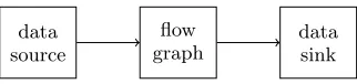
GNU Radio is a framework for building SDR and signal processing applications [3]. It provides a library of signal processing blocks. Applications are built usingflow graphs that are typically implemented using Python. The signal processing blocks are implemented in C++. GNU Radio provides a graphical editor and various GUI elements that can be used to build applications. A flow graph consists of a chain of blocks. The output of the first block, which the source, is connected to the input of the next block. The last block is connected to the data sink. A source can be for example an SDR and a sink can be an audio interface to output a decoded audible signal.
data source
flow graph
data sink
Figure 3: Structure of our SDR interface.
The structure of our SDR interface is shown in Figure 3. The data to be processed by the flow graph is first placed into the data source block. Then the flow graph is started. It processes all data and is monitored by the SDR inter-face. Upon completion, the processed data can be retrieved from the data sink. There are basically only two neces-sary modifications for ready-made SDR protocol implemen-tations: Adding data source and sink blocks for interfacing the SDR process.
Bloessl et al. have published a complete transceiver for IEEE 802.11p that is implemented using GNU Radio [2]. The transceiver was built using GNU Radio blocks only. This makes it very clean and easy to use. It was verified by com-parison against commercially available IEEE 802.11p hard-ware. For our use case all hardware-dependent parts were removed, data source and sink blocks were added and pos-sibilities to set the data rate.
To sum up, SDR is a promising application to gain deter-ministic models for the generation and decoding of signals. Only small modifications to the SDR programs are neces-sary. There is already a complete SDR transceiver for our intended prototype available.
3.3
Superposition of Discrete Signals
When more than one signal is received by a node at the same time, the involved signals interfere with each other. Interfer-ence between two signals or between a signal and noise can be described by the superposition principle that states that the signal created by interfering signals is the sum of the individual signals. The result of the overlapping signals are typically time and location dependent because propagation attenuates the signal and delays it. For simulation purposes signals are typically dealt with in a discrete representation. Superposition of discrete signals can be calculated as vector addition. However this is only possible if the signalss1 and
s2are sampled at the same absolute pointstn. See Figure 4
for an illustration of the problem. It shows two signals that are sampled at different points. To calculate the vector ad-dition of the two signals, signal (b) has to be sampled at the same time as signal (a).
t
(a)
t
(b)
Figure 4: Two discrete signals that are sampled at different absolute points in time.
Different solutions are possible to overcome this problem. One possibility is to choose the nearest sample. This ap-proach introduces an error in resulting signals. To illustrate the error, the time between two samples is defined by the sampling rate. The sampling rate for a 10 MHz channel with a complex baseband is fs = 10 Msps. The maximum time
error is then 1 2fs =
1 2·10
−6
s. In this amount of time an elec-tromagnetic wave travels approximately 15 m. Physim-Wifi uses this method [9]. While there might be no measurable difference for CSMA/CA based networks, there can be a difference in systems where superposition of signals coming from different transmitters happens intentionally.
linear interpolation was used compared to using the nearest sample, in which case there is no interpolation at all.
A superior solution is an ideal band limited sinc interpola-tion [18]. The sinc funcinterpola-tion is the impulse response of an ideal low-pass filter: sinc(x) = sin(πx)πx . By sampling the sinc function shifted by a fraction of a sampledas depicted in Equation 1 we get the impulse responseh.
hdn= sinc(n−d) =
sin(π(n−d))
π(n−d) (1) Filtering a signals withhdncreates a signals0 which is
de-layed bydsamples, withd <1 being a fraction of a sample.
The sinc function is not bounded and therefore not imple-mentable. This can be solved by windowing the sinc func-tion. We extend Equation 1 and use a windoww to limit the impulse response and obtain Equation 2.
hdn=w(n−d)
sin(π(n−d))
π(n−d) (2) In a comparison of windowing functions for fractional-delay filters the authors suggest to use the Hann window [4] as thereby the maximum error is minimal. We followed this recommendation in our fractional-delay filter implementa-tion.
To summarize this section we can state that time-correct superposition of interfering signals is necessary in order to get accurate results. To calculate the required samples a fractional-delay filter looks promising. Under which circum-stances time-correct superposition affects the result is un-clear and has yet to be investigated.
3.4
Signal Simulation
As introduced, SDR provides the building blocks for all kinds of transceivers. Moreover, a complete implementation of an IEEE 802.11p transceiver has been published. The implementedsignal simulationcan create a baseband signal from the payload and also detect and decode a signal.
protocol simulation channel model
signalbuffer
SDR
signal simulation
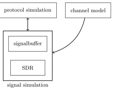
Figure 5: Structure of a network simulator con-nected to the signal simulation.
The structure of a network simulator that is connected to the signal simulation is shown in Figure 5. The signal simulation is connected to the protocol simulation, which is a network simulator without physical layer and channel model. The
protocol simulation notifies the signal simulation whenever a packet is sent. The signal simulation creates a signal using the SDR. Which nodes might be able to receive the signal is calculated using a very simple model that is based on Friis’ transmission equation. The effects of the channel between the sender and each receiving node is then calculated using the channel model. The outcome of the reception can be calculated using the receiver in the SDR.
After introducing the structure of the signal simulation the chronologically steps of the signal simulation will be depicted here:
1. The network simulator schedules an event for the be-ginning of a signal reception. The time of the sig-nal reception is determined by the time of sending the signal plus the propagation delay, which is calculated by the channel model. The signal simulation uses the SDR sender to create a corresponding signal by passing the following information: length of the signal, type of modulation and the payload. For our purposes the payload consists of a locally unique ID to be able to identify the correct signal later.
2. The created signal that consists of a set of samples is then correctly positioned in time. This means, as described in section 3.3, that the signal is processed using a fractional-delay filter. In advance the filter co-efficients are calculated according to the required frac-tional delay.
3. The resulting signal is attenuated according to the receiving power that was calculated by the channel model.
4. The delayed and attenuated signal is stored in the sig-nal buffer. The sigsig-nal buffer stores samples to replicate the voltage at the receiver’s antenna. If the current sig-nal is not overlapping with any other sigsig-nals, the sigsig-nal buffer is initialized with thermal noise. Then the signal is added to the signal buffer by using a vector addition.
5. Step 2 and 3 are repeated for every multi-path prop-agation component. The signal is superimposed with copies of itself.
6. An event is scheduled for the time the signal has been received completely. When this event occurs the signal buffer contains the original signal plus all interferences that happened while receiving the signal. The part of the signal buffer that contains the original signal and the interferences is then processed using the SDR re-ceiver. The decoder tries to detect and sync to the signal and—if it succeeds—it decodes the signal. The decoder also verifies the MAC packets checksum. Af-terwards the unique ID in the payload of the packet is verified. If two signals with the same length are being received at the same time it is otherwise not possible to verify which of the two interfering signals was decoded. However, the chance for such an incidence should be quite low.
Our prototype and a detailed description of its internal pro-cesses was introduced in this section. In the next section we describe the result of our data we conducted in a comparison between a current PHY model and our signal simulation.
4.
RESULTS
Table 1 shows the software and hardware that was used in our study. We are aware of the existence of newer versions of e.g. Veins. But as Veins 4 alpha 1 uses stochastic models of the physical layer our claims are still valid. However, Veins 4 uses a new and more realistic BER model [10] the absolute results and differences will probably vary.
Table 1: Environment of the simulation used to con-duct data.
Software
OMNeT++ 4.4
Veins 2.1
SUMO 0.17.1
GNU Radio 3.7.4 Linux 3.16.0
Hardware
CPU Intel i3-3110M Memory 8 GB
To conduct the simulation results two different systems where setup which will be explained below. The first system con-sists of Veins, which includes OMNeT++ and SUMO and our signal simulation. The second system was put in place for a more precise examination of the physical layer. It con-sists of only the signal simulation and the BER model of veins. The signal simulation is manually executed and gives a better control of the occurring signal-to-noise ratio, inter-fering of other signals and noise and the time timing of the signal.
We have used IEEE 802.11p as an example for our proto-type. The simulation parameters can be found in Table 2.
Table 2: Simulation parameters.
Channel bandwidth 10 MHz Channel frequency 5.8 GHz Symbol duration 8µs Data rate 18 Mbps
The data of the study was conducted using a modified Veins demo scenario where cars drive along predefined routes. The cars transmit beacons in a 200 ms interval. The routes in-tersect each other to increase the probability of collisions of the beacons. The simulation takes 5.6 minutes using Veins and 284 minutes using the signal simulation. For this spe-cific scenario the signal simulation introduces a 50×slower calculation time. During the simulation around 120k signal transmissions occur. Out of these about 49k signal trans-missions have a SNR>0.
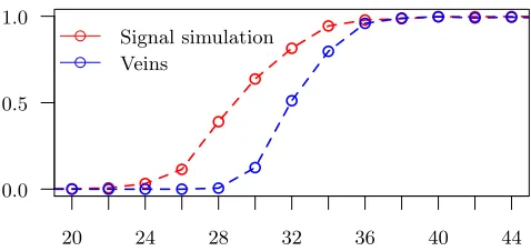
Figure 6 shows a comparison of the probability of a success-ful reception of a frame with respect to the signal to noise ratio for the signal simulation and Veins. The stochastic model of Veins is more pessimistic than our signal simula-tion. To reach a frame reception rate of 50 % the signal simulation needs a SNR of only 29 dB while Veins needs 32 dB to achieve the same rate. The gap becomes smaller
20 24 28 32 36 40 44
Signal simulation Veins
0.0 0.5 1.0
Figure 6: The frame reception rate with respect to the signal-to-noise ratio of the deterministic sig-nal simulation (red) compared to Veins’ stochastic model (blue).
as the SNR increases: For a packet reception rate of 90 % the signal simulation needs a SNR of 34 dB and Veins needs 36 dB.
20 24 28 32 36 40 44
Noise Interference 0.0
0.5 1.0
Figure 7: The frame reception rate with respect to the signal-to-noise ratio with noise only (green) or with noise and interference (blue).
Stochastic PHY models treat noise and interfering signals the same. Figure 7 shows a comparison of the probabil-ity of a successful reception of a signal with respect to the SNR for signals where only thermal noise was present (green) and signals where thermal noise and interfering signals were present. The probability of a successful reception is nearly identical for both cases. This means that stochastic models work quite well for CSMA/CA based IEEE 802.11 protocols.
4.1
Computation and Memory Costs
To be able to classify the costs of the deterministic PHY model we conducted CPU time and memory measurements. The numbers were measured on a laptop with Intel i3-3110M CPU and 8 GB of memory running Linux 3.16.0.
for connecting the flow graph of signal processing modules and we currently restart the python interpreter each time a signal is received there is great potential for optimization.
Memory usage depends only on the number of nodes and the maximum expected packet length. For each network node the signal simulation has to store two maximum length packets overlapping in 1 sample. This results in a minimum buffer length of 2×maximum signal length−1. The buffer is an array of complex floating point numbers, each sized 8 bytes. For our tests which assumed a maximum packet length of 64 symbols which results in a maximum packet length of 512 bytes. This yields a memory usage of 1 kB per node for the storage of the signals.
5.
CONCLUSION
We presented a novel approach for the accurate simulation of the physical layer. By using ready-made software-defined radio libraries there are only small adaptations necessary– compared to a complete implementation of a specific proto-col. We have implemented a prototype for the simulation of IEEE 802.11a/g/p and provided an integration in the Veins VANET simulator. However our approach is not protocol-or application specific. The prototype is a drop-in replace-ment for the Veins PHY and supports a ray-optical channel model, thus enabling the simulation of multi-path propaga-tion. However the approach is not limited to GNU Radio, IEEE 802.11a/g/p and Veins. Adaption for other network simulators such as ns-3 are possible as well as other PHY protocols and other SDR software. Future applications pos-sibly include simulation of CDMA for real-time media access and simulation of MIMO-based systems.
6.
REFERENCES
[1] C. Balanis.Antenna Theory, Analysis and Design. John Wiley & Sons, New York, 2. edition, 1997. [2] B. Bloessl, M. Segata, C. Sommer, and F. Dressler.
Towards an Open Source IEEE 802.11p Stack: A Full SDR-based Transceiver in GNURadio. In5th IEEE Vehicular Networking Conference (VNC 2013), pages 143–149, Boston, MA, December 2013. IEEE. [3] E. Blossom. GNU Radio: Tools for Exploring the
Radio Frequency Spectrum.Linux journal, 2004(122):4, 2004.
[4] G. Cain, A. Yardim, and P. Henry. Offset windowing for FIR fractional-sample delay. InAcoustics, Speech, and Signal Processing, 1995. ICASSP-95., 1995 International Conference on, volume 2, pages 1276–1279. IEEE, 1995.
[5] G. Judd and P. Steenkiste. A software architecture for physical layer wireless network emulation. In
Proceedings of the 1st international workshop on Wireless network testbeds, experimental evaluation & characterization, pages 2–9. ACM, 2006.
[6] J. Maurer.Strahlenoptisches Kanalmodell f¨ur die Fahrzeug-Fahrzeug-Funkkommunikation. PhD thesis, 2005.
[7] S. Moser, F. Kargl, and A. Keller. Interactive Realistic Simulation of Wireless Networks. InProceedings of the IEEE/EG Symposium on Interactive Ray Tracing 2007, 2007.
[8] S. Moser and F. Slomka. Towards more realistic
simulations of Ad-hoc Networks-Challenges and opportunities. InPerformance Evaluation of Computer and Telecommunication Systems
(SPECTS), 2010 International Symposium on, pages 422–427. IEEE, 2010.
[9] S. Papanastasiou, J. Mittag, E. Strom, and H. Hartenstein. Bridging the gap between physical layer emulation and network simulation. InWireless Communications and Networking Conference (WCNC), 2010 IEEE, pages 1–6, April 2010. [10] G. Pei and T. R. Henderson. Validation of OFDM
error rate model in ns-3.Boeing Research Technology, pages 1–15, 2010.
[11] A. Schmitz and L. Kobbelt. Wave propagation using the photon path map. InPE-WASUN ’06: Proceedings of the 3rd ACM international workshop on
Performance evaluation of wireless ad hoc, sensor and ubiquitous networks, pages 158–161. ACM Press, 2006. [12] A. Schmitz, T. Rick, T. Karolski, T. Kuhlen, and
L. Kobbelt. Simulation of Radio Wave Propagation by Beam Tracing. In J. Comba, K. Debattista, and D. Weiskopf, editors,Eurographics Symposium on Parallel Graphics and Visualization, 2009. [13] A. Schmitz, T. Rick, T. Karolski, T. Kuhlen, and
L. Kobbelt. Efficient Rasterization for Outdoor Radio Wave Propagation.IEEE Trans. Vis. Comput. Graph., 17(2):159–170, 2011.
[14] H. Schumacher, M. Schack, and T. Kurner. Coupling of simulators for the investigation of car-to-x communication aspects. InServices Computing Conference, 2009. APSCC 2009. IEEE Asia-Pacific, pages 58–63, Dec 2009.
[15] C. Sommer, D. Eckhoff, R. German, and F. Dressler. A Computationally Inexpensive Empirical Model of IEEE 802.11p Radio Shadowing in Urban
Environments. In8th IEEE/IFIP Conference on Wireless On demand Network Systems and Services (WONS 2011), pages 84–90, Bardonecchia, Italy, January 2011. IEEE.
[16] C. Sommer, R. German, and F. Dressler.
Bidirectionally Coupled Network and Road Traffic Simulation for Improved IVC Analysis.IEEE Transactions on Mobile Computing, 10(1):3–15, January 2011.
[17] I. Stepanov, D. Herrscher, and K. Rothermel. On the Impact of Radio Propagation Models on MANET Simulation Results. InProceedings of the 7th IFIP International Conference on Mobile and Wireless Communication Networks (MWCN 2005), Marrakech, Morocco, September 2005.
[18] V. Valimaki and T. I. Laakso. Principles of fractional delay filters. InAcoustics, Speech, and Signal
Processing, 2000. ICASSP’00. Proceedings. 2000 IEEE International Conference on, volume 6, pages