IJSRSET141114 | Received: 10 Dec 2014 | Accepted: 20 Dec 2014 | January-February 2015 [(1)1: 35-39]
Themed Section: Engineering and Technology
35
Analysis of Rectangular Patch Antenna and Circular Patch Antenna for
Bandwidth Enhancement
D. Arun Kumar1, P.Ravi Kumar2 , P.Devi Pradeep3 Department of Electronics and Communication Engineering
GMRIT, RAJAM
ABSTRACT
This paper proposes a micro-strip patch antenna operate on the dual frequency bands. The proposed antenna design consists of U slotted patch with direct coaxial probe feed technique. The U slotted patch offers a low profile, high gain, broad band and compact antenna. The proposed designs are based on patch loaded with U slots in the form of cut from the sides and center of the rectangular and circular patch. Details of the design considerations of the proposed antenna are described, and simulated results of the obtained dual-band performances are presented and discussed. The method of computation uses MOM and this is simulated by using HFSS software.
Keywords
Microstrip, Design, HFSS, Feed,MoM, Slot.
I. INTRODUCTION
Modern life depends so much on wireless technologies that one can no longer afford to be off-line for long, even during flights. Although present regulations do not allow the use of wireless devices, the aircraft industry has already begun efforts to introduce in-flight wireless connectivity [5,6]. Microstrip patch antennas have unidirectional radiation pattern and are widely considered suitable for many wireless applications. Microstrip antennas have compact size, low weight and low cost. Various shapes of patches and feed mechanisms have been studied for these antennas to improve their bandwidth or to make them operate at multiple frequencies.
Several broad-banding techniques for microstrip antennas are widely known, prominent among them use stacked [8] or parasitic patches [7].Stacked patch antennas have multilayer structure which is disadvantaged by the overall thickness and
fabrication issues related to aligning various layers precisely. Use of shorting pins though reduces the size, the achievable bandwidth is limited. Other relatively simpler approaches include using a thick, low dielectric constant substrate and/or using slots in the patch. Usually a U-shaped slot is used [4]. A U-Slot antenna has been proposed for operating bands of 3.5- 4GHz and 5.8- 6.3GHz. Dimension of these slots are individually fine-tuned for the specified performance. The feed location is moved away from the centre to compensate for the probe inductance at the high frequency band. The antenna geometry and design are introduced in section IV. Swept frequency radiation pattern measurements in the E-plane and H-plane are obtained to estimate the field distribution characteristics of the antenna and their variation with frequency and angle are studied experimentally.
PATCH ANTENNA
A patch antenna is a popular antenna type. The electric field distribution in a rectangular patch is excited in its fundamental mode. The electric field does not stop abruptly at the patch's periphery as in a cavity; Rather, the fields extend the outer periphery to some degree. These field extensions are known as fringing fields and cause the patch to radiate. Some popular analytic modeling techniques for patch antennas are based on this leaky cavity concept. Therefore, the fundamental mode of a rectangular patch is often denoted using cavity theory as the TM10 mode.
Figure.1.Basic patch antenna
The electric field in the z direction and the magnetic field components in x and y direction using a Cartesian coordinate system, where the x and y axes is parallel with the ground plane and the z-axis is perpendicular.
II. METHODS AND MATERIAL
The MoM is applicable to problems involving currents on metallic and dielectric structures and radiation in free space. The structures are electrically small and are typically made of metals, although special extensions allow the inclusion of dielectrics, either as layered dielectrics or as finite sized shapes. The MoM solution procedure was applied to electromagnetic scattering problems. Consider a linear operator equation given by
AX Y
(1)
Where A represents the integral operator, Y is known excitation function and X is the unknown response function to be determined. Now let X be represented by a set of known functions.
X= i
i n
i p
1(2)
Where α are scalar constant to be determined substituting eq. (1) into eq. (2), and using the linearity of A. We have
i n
i
1
Y
i
A
(3)The simplicity of the method lies in choosing the proper set of expansion and testing functions to solve the problem at hand. Further, the method provides a most accurate result if properly applied. While applying the method of moments to complex practical problems, the solution region, in general, is divided into triangular or rectangular sub domains. Then, one can define suitable basis and testing functions and develop a general algorithm to solve the electromagnetic problem.
Researchers have investigated a scheme of generating the full impedance matrix of the MoM method by partitioning out on a row-by-row and column-by-column basis to a suit of processors.
DESIGN CONSIDERATION OF THE PROPOSED ANTENNA
The geometries of the considered antennas are given below
Figure.3. Geometry of the rectangular microstrip antenna with three slots
Fig.2 shows geometry of the rectangular patch antenna without any slot in it and Fig.3 shows geometry of broad band rectangular microstrip antenna with three U-slots. The rectangular patch has length and width of 52mm, 71mm and circular patch with radius 30mm and is printed on grounded substrate of thickness (h) 2.87mm, relative permittivity (ε) 3.5 and size 70mm ×100mm. The values of h and ε and resonant frequency are fixed previously and patch length and width ware determined using transmission line model [2]. The patches fed by a co-axial probe along the central line (x-axis) at the distance of 9mm
Table I : Values Of The Design Parameters
PARAMETER DIMENSIONS(mm)
Feed 9
Patch L=52,W=71
Substrate LS=70, WS=100 Length Of Vertical Outer
Slot
Is1=36
Length Of Horizontal Outer Slot
lb1=18
Width Of the Outer Slot Ws1=4 Length Of Vertical Inner
Slot1
Is2=13
Length Of Horizontal Inner Slot1
lb2=4
Width Of the Inner Slot1 Ws2=2 Length Of Vertical Inner
Slot2
Is3=7
Length Of Horizontal Inner Slot2
lb3=2
Width Of the Inner Slot2 Ws3=1
III.RESULTS AND DISCUSSION
Figure.4. Rectangular patch without slot.
Figure.5. Rectangular patch with edge and center slots.
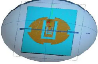
Figure.6. Circular patch with edge and center slots.
Figure.8. Rectangular Patch with one slot S-Parameter graph.
Figure.9. Rectangular patch with two slots S-Parameter graph.
Figure.10. Rectangular patch with three slots S-Parameter graph.
Figure.11. Rectangular patch with edge and center slots
Figure.12. Circular patch with edge and center slots
As per Fig.11 results of rectangular patch with edge and center slots we have obtained triple band with increments 22.94%, 13.494%, 7.75% respectively. As per Fig.12 results of the combined structure that means circular patch with both edge slots and center slots we have obtained dual band with increments 7.84%, 6.09% respectively.
Figure.13.Comparison of rectangular patch with no slot and rectangular patch with slot
As per the Fig.13 results of patch without slot, patches with 1, 2 and 3 center slots are compared and concluded that incase of without slot structure we have obtained one band and its increment up to 6.053%. Whereas in case of patch with 1,2 and 3 slots we have obtained dual band with increments 19.94%,24.744%,26.054% respectively.
Figure.14.Band width comparison of Rectangular patch antenna with circular 0
5 10
w
ith
o
u
…
w
ith
…
o
n
e…
w
ith
…
tw
o
…
w
ith
…
th
re
e
…
FL(GHz)
FH(GHz)
0.00% 5.00% 10.00% 15.00% 20.00% 25.00%
RECTANGULAR PATCH
As per the Fig.14 results of rectangular patch with edge and center slots compared with circular patch with edge and center slots and concluded that in case of rectangular patch with slot structure we have obtained triple band and its increment up to 22.94%.Whareas in case of circular patch with edge and center slot structure we have obtained dual band and its increment up to 7.84% only.
IV.CONCLUSION
The insertion of the slot increases the bandwidth. In this paper it is shown that introduction of three slots in center have massively increased the bandwidth up to 26.054% and also a dual band is obtained. This paper investigating edge slots also. When edge slot are introduced in same structure in all sides, the results are favorable for GPS and GSM application and in this case also bandwidth is increased. Now slots are introduced in both middle and in all sides of rectangular patch and circular patch. In such case triple band and dual band was obtained and bandwidth also increased up to 22.94%, 7.84% respectively. The comparison result shows that band width was more in rectangular patch antenna.
V. REFERENCES
[1] Sankar, K.; Bargavi, R.; Arivumani Samson, S., "Single Layer Dual band G-shaped patch antenna," Communications and Signal Processing (ICCSP), 2014 International Conference on , vol., no., pp.636,639, 3-5 April 2014
[2] B.Vedaprabu and k.j. Vinoy “An integrated wideband multifunctional Antenna using a microstrip patch with two U-slots” progress in electromagnetic research B.vol. 22, 221-235, 2010.
[3] Sanjeev kumar Sharma “Analysis of Board banding and minimization techniques for square patch antenna”IETE journal of reserch vol.56 March-April 2010
[4] M.T.Islam,M.N. Shakib an N.Misran “Multi-slotted Micostrip patch antenna for wireless communication” progress in electromagnetic research letters,vol.10,2009.
[5] Shackleford,A.K. .,K.F.Lee, and Luk,”Design of small size wide-bandwidth microstrip patch antennas”,IEEE Antennas and propagation magazine,vol.45 75-83 Feb.2003.
[6] Niebla, c.p..,” coverage and capacity planning for aircraft in-cabin wireless heterogeneous networl”,proc.IEEE vehicular technology conference 2003-fall,1658-1662,oct. 6-9., 2003
[7] Diaz, N.R. and M.Holzbock,”Aircraft cabin propagation for multimedia communations,” proc. European Mobile/Personal satcorns conference 2002, sep. 25-26, 2002.
[8] Chen,W.,K.F. Lee and R.Q.Lee, “spectral-domain moment method analysis of coplanar microstrip parasitic subarrays”,Mirow.opt.technol.Lett vol6.No.3 157-163,1993.