2nd International Conference on Current Research Trends in Engineering and Technology
© 2018 IJSRSET | Volume 4 | Issue 5 | Print ISSN: 2395-1990 | Online ISSN : 2394-4099 Themed Section: Engineering and Technology
Wheel Alignment Detection using Raspberry pi
Mulla Minaz
1, Soni Drupad
2, Tale Hetal
3, Gandhi Maulik
4, Dr. Sheshang Degadwala
51-4U.G.B.E. Student Computer Engineering, Sigma Institute of Engineering, Vadodara, Gujarat, India
5Head of Department, Computer Engineering, Sigma Institute of Engineering, Vadodara, Gujarat, India
ABSTRACT
Wheel Alignment detection using Raspberry Pi - The development of automobile technology is evolving and the influence of automobile stability to travel safely is increasing. A modern person usually has wheel alignments both for front and rear wheels. For that detection is needed, here comes the role of our device. Here 3 elements are important Camber, Castor and Toe which needs to be looked after for alignment. All four tires should be in straight line. A further thing which matters is Knuckle, Bearing and Jumper. By rash driving alignment gets disturbed which affects tire wear and tear. Here, user can get affected by frequent tire replacement which leads to cost on maintenance. Here, every tire calculations are different and they should be precise. For maintaining that using sensors calculations are maintained which can be done using Raspberry Pi and Python as implementation language.
Keywords: Wheelalignment, Detection, Wheels, Raspberry Pi, Sensors
I.
INTRODUCTIONGradually, awareness of wheel alignment and air tire pressure is increasing in automobile owner community. More awareness leads to better vehicle performance and stability, which means low maintenance cost and long tire life. Many techniques have been developed to detect misalignment of tires. None of them are attached to vehicle chassis. An efficient alignment detection system must be able to detect variations in any angles while being attached to vehicle chassis. In reality, making any theory work is a difficult task.
In this paper, a powerful detection system has been proposed. The system is build using IR sensors and TPMS which will be mounted on vehicle chassis. While vehicle is stable TPMS will check air tire pressure later while vehicle is in movement wheel alignment will be checked as alignment can be
detected accurately while vehicle is in movement, which helps tire to stay in straight direction.
II.
RELATED WORKwhich is perfectly fixed and parallel to the wheel obtain on receiver part through LED. If light of LED is bright then alignment is proper. Degree of accuracy obtains on laptop which is connected to Arduino board via USB Cord. It is using Arduino Microcontroller ATMEGA328P in its hardware environment and the whole system is designed according to it. ATMEGA328 Microcontroller read this signal through C++ coding and converts this analog input into decimal and final output of the system view on laptop, its 2-D view of wheel alignment. The function of Arduino 328 microcontroller read this 2-signal which is transmitted through IR sensor.
In [2], Nirmalkumar N. Salave and Pravin L. Sarode describes the real time wheel alignment of vehicle. This system is measuring values of camber angle, caster angle, toe angle, thrust angle and turning radius of wheel using IR sensors. This is static Alignment measurement. First of all vehicle is parked on alignment bay. When the machine is started initial stage of alignment screen is shown on computer screen. All measured values are computed with the help of software and at the end it shows whether wheels are aligned or not. In [3], Ankita K. Patil and Prof. V. L. Kadlag;
describesthe: “Design Of Wheel Alignment Measuring System Using Infrared Transformation” in which concentration on the parameter like camber-angle, caster-angle, toe-in & toe-out angles. This work simultaneously carried out by using IR (Infrared transmission) where, the output is observed with change in angular displacement. During Wheel Alignment rotated about x and y axis, camber and toe are recorded by the IR Sensors and digitalized on the display using Microsoft visual studio programming. And software output (i.e. angles in degrees) are validated using protractor fixed around the wheel. Every time noticing same accuracy of readings. Positive toe and negative toe is calculated with the alert message of tire wear in percentage. Also, an alarm is generated when normal. Outputs of IR
rays are given to the Arduino Board for signal processing. At end, using USB interface, wheel alignment system get connected with display unit via VB.net.technology is used to convert infrared radiation into digital signals.
In [4], Sonali Chatur describesabout: “Computer Based Wireless Automobile Wheel Alignment System Using Accelerometer” Which use Accelerometer for the measurement of Toe & Camber. Wheel alignment detection system is appropriative equipment that inspects vehicle’s wheel positioning parameter and detects positioning of parameters including wheel toe, camber, caster, steering axle inclination(SAI) based on the establishment of the wheel geometric model and technologies of sensor, laser and image processing. In the process, tire wear is most effective part of the system, in which number of factors are affected like wheel alignment, vehicle overloading and also from the vibration in tire, predict tire wear. Wrong toe setting can lead to the incorrect wheel alignment & thus the result in fastest tire wear. Accelerometer is used to measure toe & camber angles form x, y and z-axis. The advantage of the system is it is cost effective and data transmitted through system is wireless and the other side disadvantage of the system is Air tire Pressure detection not done, which plays vital role in alignment. System is not mounted on the vehicle.
generates result if tire is misalignment, on the base of resultant image blob detection from Open CV library in Visual Studio 2012 platform is used for depth map of the wheel rim. It is dependent on the detection of rim and measuring angle of wheel rim and shaft point. In this technique, everything depends on how accurately detection of wheel rim is done as is follows to shape and radius of rim. And later as per predefined values of model calculations are made w.r.t detection of rim. In [6], Vinayak A. Prabhu, Ashutosh Tiwari,
Windo Hutabarat, John Thrower and Christopher Turner describes “Dynamic Wheel Alignment Control Using Depth Imagery Process” in which they are proposing use of infrared light for automated wheel loading operation control. First of all, they’re tracking motion of the wheel and according to spatial analyzed position of the wheel they are applying depth imagery using IR depth imaging devices like Microsoft Kinect and Asus Xtion. For three-dimension scene they are using these two devices. Xtion captures static wheel’s depth images whereas Kinect is for moving wheel. They have some angular values which identifies boundaries of possibilities of values captures. Alignment is checked with respect to actual values.
III. METHODS AND MATERIAL
HARDWARE COMPONENTS:
A. RASPBERRY Pi
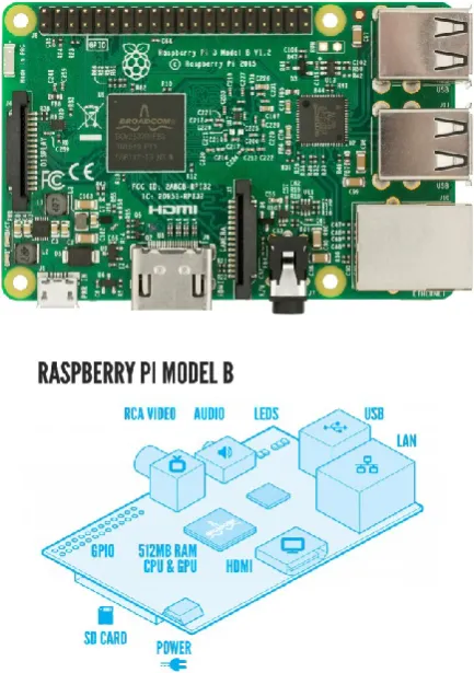
• The Raspberry Pi is a series of small single-board computers developed in the United Kingdom by the Raspberry Pi Foundationto promote the teaching of basic computer science in schools and in developing countries The original model became far more popular than anticipated, selling outside its target market for uses such as robotics.
• It does not include peripherals (such as keyboards, mice and cases). However, some accessories have been included in several official and unofficial bundles.
• According to the Raspberry Pi Foundation, over 5 million Raspberry Pi’s were sold by February 2015, making it the best-selling British computer. By November 2016 they had sold 11 million units, and 12.5m by March 2017, making it the third best-selling "general purpose computer". In July 2017, sales reached nearly 15 million
Figure 1. Raspberry Pi
B. INFRARED SENSOR
Figure 2. Infrared Sensor
C. DC MOTOR
• A DC motor is any of a class of rotary electrical machines that converts direct current electrical energy into mechanical energy. The most common types rely on the forces produced by magnetic fields. Nearly all types of DC motors have some internal mechanism, either electromechanical or electronic, to periodically change the direction of current flow in part of the motor.
• DC motors were the first type widely used, since they could be powered from existing direct-current lighting power distribution systems.
• A DC motor's speed can be controlled over a wide range, using either a variable supply voltage or by changing the strength of current in its field windings. Small DC motors are used in tools, toys, and appliances. The universal motor can operate on direct current but is a lightweight motor used for portable power tools and appliances. Larger DC motors are used in propulsion of electric vehicles, elevator and hoists, or in drives for steel rolling mills. The advent of power electronics has made replacement of DC motors with AC motors possible in many applications.
Figure 3. DC Motor
D. TPMS SENSOR
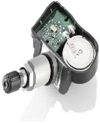
• A tire-pressure monitoring system (TPMS) is an electronic system designed to monitor the air pressure inside the pneumatic tires on various types of vehicles. TPMS report real-time tire-pressure information to the driver of the vehicle, either via a gauge, a pictogram display, or a simple low-pressure warning light. TPMS can be divided into two different types – direct (dTPMS) and indirect (iTPMS). TPMS are provided both at an OEM (factory) level as well as an aftermarket solution. The target of a TPMS is avoiding traffic accidents, poor fuel economy, and increased tire wear due to under-inflated tires through early recognition of a hazardous state of the tires.There are mainly two types of TPMS direct TPMS and indirect TPMS.
Figure 4. TPMS Sensor
E. GSM MODULE
modems support a common set of standard AT commands. You can use a GSM modem just like a dial-up modem.
• In addition to the standard AT commands, GSM modems support an extended set of AT commands. These extended AT commands are defined in the GSM standards. With the extended AT commands, you can do things like:
• Reading, writing and deleting SMS messages.
• Sending SMS messages.
• Monitoring the signal strength.
• Monitoring the charging status and charge level of the battery.
• Reading, writing and searching phone book entries.
• The number of SMS messages that can be processed by a GSM modem per minute is very low -- only about six to ten SMS messages per minute.
Figure 5. GSM Module
F. LCD
• An LCD display is a flat panel display, which uses an array of light-emitting diodes as pixels for a video display. Their brightness allows them to be used outdoors where they are visible in the sun store signs and billboards, and in recent years they have also become commonly used in destination signs on public transport vehicles. LCD displays are capable of providing general illumination in addition to visual display, as when used for stage lighting or other decorative (as opposed to informational) purposes.
Figure 6. LCD
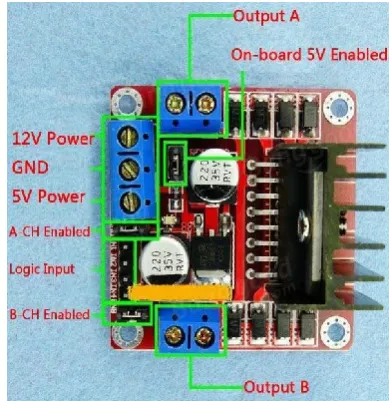
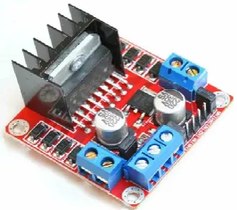
G. L298N MOTOR DRIVER CIRCUIT MODULE
• We'll explain how to use our L298N
H-bridge Dual Motor Controller Module 2A with Arduino.
• This allows you to control the speed and direction
of two DC motors, or control one bipolar stepper motor with ease.
• The L298N H-bridge module can be used with
motors that have a voltage of between 5 and 35V DC.
• There is also an onboard 5V regulator, so if your supply voltage is up to 12V you can also source 5V from the board.
• These L298 H-bridge dual motor controller
Figure 7. L298n Motor Driver Circuit Module
H. HT12E WIRELESS MODULE--HT12D
• In this instructable you'll can send and receive data using very very cheap components!
• With the help of our friends HT12E (ENCODER) and HT12D (DECODER) and a pair of Rf modules of 433 Mhz.
• RF transmitter and RF receiver of 433 Mhz
• 3 push buttons
• IC HT12D
• IC HT12E
• Hearders (male or female it doesn't care)
• 3 resistors with a value from (100 to 330) ohms
• 3 leds any color 3mm of diameter (miniature)
• 1 Megaohm resistor for IC of the transmitter (IMPORTANT)
• a 51 K or very very neraly resistor value for the receptor (IMPORTANT)
Figure 8(A). HT12D Wireless Module
Figure 8(B). HT12E Wireless Module
Figure 8(C). HT12D Wireless Circuit
Figure 8(D). HT12E Wireless Circuit Diagram
I. 12V BATTERY AND 9 HWB
• The most common battery chargers we sell are for 12 volt batteries. We carry a wide range of chargers for many different scenarios, from a small sealed lead acid battery to large wheel chargers you would find in a professional garage. We carry chargers from well-known brands, such as Battery MINDer, NOCO, and Battery Tender. Every charger we sell is backed with a manufacturer warranty.
• The nine-volt battery, or 9-volt battery, is a common size of battery that was introduced for the early transistor radios. It has a rectangular prism shape with rounded edges and a polarized snap connector at the top.
• This type is commonly used in walkie-talkies, clocks and smoke detectors.
• The nine-volt battery format is commonly available in primary carbon-zinc and alkaline chemistry, in primary lithium iron disulfide, and in rechargeable form in nickel-cadmium, nickel-metal hydride and lithium-ion. Mercury-oxide batteries of this format, once common, have not been manufactured in many years due to their mercury content.
Figure 9(A). 9 HWB Battery
Figure 9(B). 12v Battery
J. PUSH BUTTON & ON-OFF BUTTON
• A push-button (also spelled pushbutton) or simply button is a simple switch mechanism for controlling some aspect of a machine or a process. Buttons are typically made out of hard material, usually plastic or metal.
• He surface is usually flat or shaped to accommodate the human finger or hand, so as to be easily depressed or pushed. Buttons are most often biased switches, although many un-biased buttons (due to their physical nature) still require a spring to return to their un-pushed state.
• Terms for the "pushing" of a button include pressing, depressing, mashing, hitting, and punching.
• The mechanism of a switch removes or restores the conducting path in a circuit when it is operated.
• It may be operated manually, for example, a light switch or a keyboard button, may be operated by a moving object such as a door, or may be operated by some sensing element for pressure, temperature or flow.
Figure 10(A). On-Off Button
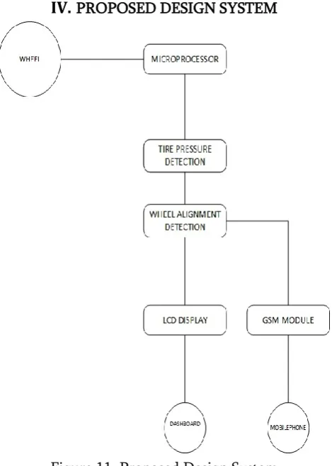
IV. PROPOSED DESIGN SYSTEM
Figure 11. Proposed Design System
ALGORITHM
INPUT: Sensor-tire measured distance.
OUTPUT: Display Result to the user on mobile phone and via LED’s.
Implementation Of Algorithm For Problem Description: Measuring distance from sensor to tires for misalignment. Step 1: Sensor detection.
Step 2: Air tire pressure detection. Step 3: Sensor measurement calculation. Step 4: Wheel Misalignment angle detection.
Step 5: Notification through LED and message notification via GSM module.
V.
RESULTS AND DISCUSSION• Results generated after working on this project are successful notification through LED lights, messages passing through LCD display which is used for prompt notification.
• This are testing results of LCD notification display:
Figure 12(A). Result of LCD Display
Figure 12(B). Result of LCD Display
• This is result of LED light notification while testing:
Figure 13. Result of LED Notification
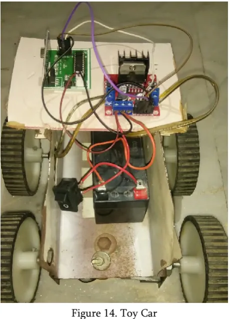
• Toy car developed for presenting this project:
Figure 14. Toy Car
• Motors used and connection done for that are below in toy car:
Figure 15. Motors Connection
Figure 16. Remote
• Here, we are focused on making working of toy car using 4 300rms motors and transceiver circuit using which car would run wirelessly and on chassis of car sensors will mounted which would help detecting distance between tires and chassis. Displacement will be compared with default values measured manually.
• We are using here raspberry pi as computer performing multi task of
• Tire pressure detection
• Sensor detection
• Sensor calculation
• Notification
VI. CONCLUSION
We have completed our project work based on using software engineering and system analysis and design approach. Work that we have done with preplanning scheduling related with time constrains and result oriented progress in project development. Here, we conclude safety and security of Car owner. Performance enhancement and improved mileage is ensured. Stability, handling of vehicle improves which results in delay of tire replacement.
VII.
REFERENCES[1].
Jigar Senjalia, Parinda Pandya, Harsh Kapadia: “Measurement of Wheel Alignment Using Camera Calibration And Laser Triangulation”[5], NUiCONE, Nirma University.[2].
VINAYAK A Prabhu, Ashutosh Tiwari, WindoHutabarat, John Thrower, Christopher Turner: “Dynamic Alignment Control Using Depth Imagery For Automated Wheel Assembly”[6], CIRP 25 ( 2014 ).Commercial Vehicle”[2], IJLERA, Volume-02, Issue-06, June-2017, PP-64-70.
[4].
Shweta G. Barhe, Balaji G. Gawalwad.,Measurement of “Wheel Alignment Using IR Sensors”[1] , IJIRCCE, Vol. 4, Issue 5, May 2016.[5].
Ankita K. Patil, Prof. V. L. Kadlag, “Design of Wheel Alignment Measuring System Using Infrared Transformation”[3], IJTRA, e-ISSN: 2320-8163, Volume 4, Issue 5 (Sept - Oct, 2016), PP. 4-6.[6].
Sonali Chatur Department of Electronics Engineering, K.J.Somaiya College of Engineering, Mumbai University, Maharashtra, India: “Computer Based Wireless Automobile Wheel Alignment System Using Accelerometer”[4] , IJES, Volume-4 Issue-9, Pages, PP -62-69, 2015.[7].
UML Distilled: A Brief Guide to the Standard Object Modeling Language (3rd Edition) by Martin Fowler.[8].
Object Oriented Modeling and Design with UML Michael Blaha and James Rambaugh – PEARSON second edition.[9].
Python Pocket Reference by O’Reilly[10].
https://www.universalmind.com/blog/rasp berry-pi-vs-arduino-when-to-use-which/[11].
http://www.rhydolabz.com/wiki/?p=1632 5[12].
http://www.instructables.com/id/RASPBE RRY-PI-3-and-RASPBIAN-JESSIE-GSM-3G-SERIAL-H/[13].
http://yospeed.com/wheel-alignment-explained-camber-caster-toe/[14].
https://www.merriam-webster.com/dictionary/camber
[15].
http://binaryupdates.com/introduction-of-raspberry-pi-3-model-b/[16].
http://challengeforsustainability.org/toolki t/energy-efficiency/motion-sensors/[17].
https://hackaday.com/2016/02/28/introduc ing-the-raspberry-pi-3/[18].
https://www.slideshare.net/ltg_oxford/ras pberry-pie-an-introduction[19].
https://www.raspberrypi.org/documentati on/usage/python/[20].
http://opensourceforu.com/2016/10/progr amming-raspberry-pi-with-python/[21].
https://circuitdigest.com/microcontroller-projects/raspberry-pi-phone-by-interfacing-gsm-module