The Face Object based HEVC System for Video Call
Xi Wang
Key Lab of Intelligent Information Processing,Chinese Academy of Sciences(CAS) Institute of Computing
Technology, CAS University of Chinese Academy of Sciences, Beijing,
100190, China
[email protected]
Chenggang Clarence Yan
Department of Automation,Tsinghua University Key Lab of Intelligent Information Processing , CAS
Institute of Computing Technology, CAS, Beijing,
100190, China
[email protected]
Qingming Huang
Key Lab of Intelligent Information Processing, CASInstitute of Computing Technology, CAS University of Chinese Academy of Sciences, Beijing,
100190, China
[email protected]
Li Su
Key Lab of Intelligent Information Processing, CASUniversity of Chinese Academy of Sciences, Beijing,
100190, China
[email protected]
Shuqiang Jiang
Key Lab of Intelligent Information Processing, CASInstitute of Computing Technology, CAS Beijing, 100190, China
[email protected]
Xianglin Huang
Communication University of China (CUC), Beijing, 100024,China
[email protected]
ABSTRACT
Guaranteing the quality of face object in video call is the key task for video coding systems under the constrained bandwidth of network. Conventionally, the face object is divided into disperse blocks under the hybrid coding frame-work. Therefore, the characteristics of the complete face object have not been fully used. Meanwhile, it is difficult to predict the complex affine transformations such as rotation and scaling of the face object in neighboring frames based on the current translation motion model.
In this paper, we propose an improved video coding scheme for video call. The complex transformation of complete face object is used to improve the compression effect. Experi-mental results show that our proposed method has better performance compared with HM12.0, the bits rate saving of face region is up to 19.59% under the similar visual quality .
Categories and Subject Descriptors
I.4.2 [IMAGE PROCESSING AND COMPUTER VI-SION]: Compression (Coding); H.4 [INFORMATION SYS-TEMS APPLICATIONS]: Communications Application-s—Computer conferencing, teleconferencing, and videocon-ferencing
General Terms
Algorithms, Experimentation
Keywords
Video coding, video calls, referent picture set, face process-ing
1.
INTRODUCTION
In the recent years, video calls have been widely applied with the rapid development of internet and mobile commu-nication technology. Meanwhile, more advanced displaying devices ask higher video quality for good visual effects. How to guarantee the visual quality of conversational videos un-der the limited bandwidth is a challenging topic.
Most of the improved methods of conversational video cod-ing are based on the Region-Of-Interest (ROI) detection[7]. At the encoder side, the quantization parameter and the Rate Distortion Optimization (RDO) Lagrange multiplier[14] are adapted to make the face region corresponds to higher distortion sensitivity[18][8]. At the decoder side, the face region is taken as the most interested area to perform er-ror recovery or erer-ror resilient[6][2]. Beyond that, a very low frame-rate video coding strategy for face-to-face teleconfer-ence proposed by Wang et al. [15]. To reduce the frame rate, only some selected high quality frames will be encod-ed. These methods just weighted the face region as a key area, the features of the complete face object e.g. rotation and scaling have not been fully take account for encoding.
In the latest High Efficiency Video Coding (HEVC)[13] stan-dard, the rotation transformation has been utilized to the intra prediction[21][20]. It is effectively for reducing the bits rate. However, due to the coding cost, the complex affine transformation is hard to use to the inter prediction[19]. There are several methods dedicated to the complex mo-tion predicmo-tion. Zhanget al.[10] proposed an additional
mo-MOBIMEDIA 2015, May 25-27, Chengdu, People's Republic of China Copyright © 2015 ICST
tion candidate of merge mode. The additional complex mo-tion is predict by using the momo-tion informamo-tion from nearest neighbors. Roman et al.[5] proposed an affine motion field prediction based on translational Motion Vectors (MVs) for better modeling complex motion, which is used as a post-processing step after mode decision and Motion Estimation (ME). A parametric skip mode based on higher-order para-metric motion model is presented in[3] for better prediction of complex motion. The methods described above estimat-ed the rough complex affine transformation by translation motions of nearly units, but did not consider it as a the in-dependent object. In our previous work[16], we established a personal face patch database for performing face distor-tion recovery of conversadistor-tional videos at the decoder side, which gains high quality promotion by utilized the correla-tions of the face object such as complex affine transforma-tion. This scheme is worked for the reconstructed conversa-tional videos, and it is independent of the CODEC.
In this paper, we introduce the complex affine transforma-tion to predictransforma-tion procedure for video calls. The face objects in the conversational videos are detected at first. Then, the exact affine transformation of face objects in adjacent frames are obtained and used to reset the referent picture set. The inter prediction of our scheme is based on the new referent picture which is much closer to the current frame.
The rest of this paper is organized as follows: The procedure of our proposed scheme is given in Section 2. In this sec-tion, the details of face processing and the modified encoding procedures are also be presented . In Section 3, the experi-mental results are reported. Finally, the paper is concluded in Section 4.
2.
THE FACE OBJECT BASED VIDEO
COD-ING SYSTEM
The flowchart of the face object based encoding system for video call in show in Figure .1. Assume that the current input frame is I0. First, a face detection program will be
performed to locate the face region onI0. The position of
the face will be recorded when there is a face.
Then, we check the referent pictures set (RPS) ofI0.
Sup-portR is a referent picture of the current frame I0. If R
also have a face region,R should be aligned toI0 to make
the face region ofRmaximum approximate to the one ofI0.
The aligned pictureR′ will be added to the RPS ofI0.
Finally,I0 will be compressed by using the new RPS. And
the alignment parameters need to transfer to the decoder side. Due to the new referent pictureR′is used by the whole slice rather than a unit, we encode the alignment parameters in the slice header ofI0. After that,R
′
will be deleted from the RPS.
It should be noticed that theItype slice does not have RP-S, therefore, the additional referent picture doesn’t work on the Intra prediction. However, theIframes can be used as referent pictures. For this reason, the face detection pro-cedure should be also executed to theI frames. For each frame, the face detection procedure performs only once, and the detection results will be recorded.
Figure 1: The flowchart of the face object based coding system at encoder side
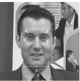
Figure 2: The obtained feature points and face re-gion
2.1
Face Processing Procedures
The quality of face region is the most important thing in a video call. The proposed improved coding system is designed for the video call. Therefore, to process the face is one of the key steps in our work. It mainly contain two parts, 1) Face detection; 2) Face alignment.
2.1.1
Face Detection
The first goal of face detection is to check weather there is a big face in the current frame. If there is a face, the region of the face and the position of the eyes are needed. Milborrow
et al.[9] proposed an effective algorithm to locate facial fea-tures with an extended active shape model (STASM)1. The
method in [9] is adopted to detect the face in our paper. A diagram of detection result is shown as Figure .2.
If the current frame contains a face, by performing the al-gorithm STASM, 76 facial feature points can be obtained,
1The source code of STASM can be downloaded from
(a)GI0
(b)GR′ (c)G′R′ (d)E
Figure 3: A diagram of elements in function(3). The testing images are taken from the Labeled Faces in the Wild (LFW) [4] dataset.
else the number of points return 0. 7 of these points are which we needed. The position of the 7 feature points are marked in Figure .2. Point 1 and point 3 are used to locate the left and right boundary of the face region, respectively. Point 2 is marked to get the bottom boundary. The upper boundary is defined by the toper one of point 4 and point 5. Point 6 and Point 7 describe the eyes position which are recorded for the face aligning step.
2.1.2
Face Alignment
In this section, the goal is to minimal the difference between the face region of current frame I0 and the one of aligned
referent picture R′. After face detection, the face region and eyes position ofI0 and original referent pictureR can
be obtained. The objective function of face alignment in our paper can be define as:
min R′,τ
∥GI0−GR′∥2 s.t. R
′
=R◦τ (1)
where Gx represents the face region of picture x. τ is a image affine transformation matrix which is computed as:
τ =
S0u S0v 00
0 0 1
−cossinθθ cossinθθ 00
0 0 1
10 01 00
Tu Tv 1
(2)
where
S0u S0v 00
0 0 1
is the image scaling transformation
matrix,
−cossinθθ cossinθθ 00
0 0 1
and
10 01 00
Tu Tv 1
describe
the image rotation and translation transformation matrix, respectively. Which means the aligning transformation con-tains scaling, rotation and translation but does not processes the distortion transformation and perspective transforma-tion.
In order to deal with occlusions, minR′,τ∥GI0−GR′∥2 can be switched to the similar function minR′,τrank([GI0G
′
R′])
(a)
(b) (c)
(d) (e)
Figure 4: A diagram of the effect of face alignment. (a) FrameI0(b) FrameR(c) The minimum residuals error of face regions in I0 and R. (d) The aligned picture R′, R′ =R◦τ. (e) The minimum residuals error of face regions in I0 and R
′
. The horizontal axis and vertical axis are painted in (d). It can be observed that,R′ is obtained through slight rotating and shrinking on R, and the residuals error shown in (e) is smaller than the one shown in (c).
in Equation(1), whereG′R′ =GR′+E,Eis a noise matrix. Then, the formulation (1) can be modified as follows:
min R′,τ
rank([GI0G
′
R′])s.t. R
′
=R◦τ, ∥E∥0≤k (3)
where the ℓ0 norm∥ · ∥0 computes the number of nonzero
elements in the error matrix E, and k is a given constant that describes the maximum number of corrupted pixels of
GR′. A diagram ofGI0,GR′,G
′
R′ andEis shown in Figure .3. In our previous work[17], we designed a fast method based on the algorithm proposed byYigang Peng et al.[11] to solve the function(3). The details are represented in [17]. After face alignment, the face region in new referent picture
R′ gets to be more similar to the one in current frame I0.
An example of face aligning results is shown as Figure .4. It can be observed that the residuals error is much smaller after doing face alignment.
2.2
Encoding Procedures
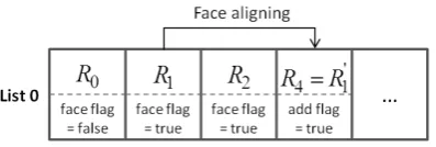
After getting the new referent pictureR′, it needs to addR′
Figure 5: The referent picture list
2.2.1
Setting the Referent Picture Set
The RPS in HEVC decides how perviously decoded pictures are managed in a decoded picture buffer (DPB) in order to be used for reference[12]. Reference picture list initialization creates defaultList 0 and List 1. Due to the low-delay requirement of video calls, we just adoptItype andPtype slices for coding. Therefore, onlyList 0will be used.
As shown in Figure .5, each picture in theList 0has gone through the face detection procedure. A flag is defined to mark weather this picture has a face. A new picture will be created for the first facial picture in the list, and be added to follow the last referent picture. Of course, the index of refer-ent pictures should not be bigger than the allowed maximum number of referent pictures.
2.2.2
Encoding the Slice Header
If the aligned referent picture is added, it needs do the same step in the decoder side. Therefore, the image affine trans-formation matrixτ should be coded into the slice header.
τ=
−SSuvcossinθθ SSuvcossinθθ 00
Tu Tv 1
can be obtained from
equa-tion (2). 6 elements ofτ need to be encoded. In generally, the data type of τ is double float type. It needs 64 bits for each element, it is too much to encoding. We divided one element into several parts to encode. The parameters are shown as Table .1. The encoding structures ofτ(0,0),
τ(0,1) andτ(2,0) are given. And the structures ofτ(1,0),
τ(1,1) and τ(2,1) are the same as τ(0,1)’s, τ(0,0)’s and
τ(2,0)’s, respectively.
Table 1: Parameters and Descriptions Parameter Type Description
add ref flag Bool Weather add a new referent pic-ture
add ref no UInt The index of originalRin RPS sc u flag Bool The sign ofτ(0,0)
I sc u UInt The integer part ofτ(0,0) D sc u UInt The decimal part ofτ(0,0) ss u flag Bool The sign ofτ(0,1)
I ss u UInt The integer part ofτ(0,1) D ss u UInt The decimal part ofτ(0,1) t u flag Bool The sign ofτ(2,0)
I t u UInt The integer part ofτ(2,0) D t u UInt The decimal part ofτ(2,0)
The decimal parts ofτ(0,0) andτ(0,1) accurate to 6 deci-mal places to ensure that for the 4096p sequences the error can be limited within 0.1 pixels. It costs 3 bits to encode the decimal part ofτ(2,0) to make the translation transfor-mation is accurate to 18 pixels. Andτ(0,0) are recorded as
(τ(0,0)−1) because thatτ(0,0) is closely to 1 in most time.
At the decoder side, τ is reconstructed by the above rules. And the procedure of setting RPS is the same as encoder side.
3.
VALIDATIONS
To validate the proposed scheme, we integrate it into HEVC reference software HM12.0 [1]. All test video sequences are in YCbCr 4:2:0 format. The common coding configurations are set as Table .2. Evaluations are performed to compare the proposed method with HM12.0.
Table 2: The value of configure parameters Option Value
cfg file encoder lowdelay P main.cfg
Profile main
MaxCUWidth 32 MaxCUHeight 32 MaxPartitionDepth 2
QuadtreeTU 2
MaxDepthInter
IntraPeriod -1
GOPSize 1
QPoffset 0
InternalBitDepth 8
In our paper, 4 YUV sequences (Johnny, KristenAndSara, suzie, GreenCloth) are used to test. Johnny (1280x720),
KristenAndSara (1280x720) andsuzie (720x480) are the s-tandard YUV sequences. Due to the goal of our method is focus on the face object, and the face regions of John-ny andKristenAndSara are small, therefore, we resize this 2 sequences to 480x480 by cutting a part of background in the frames. The new frames of them are shown in Figure. 7. Sequence GreenCloth (640x640) is created by our own. It can be obtained by contacting authors.
All test YUV sequences are encoded with three different sets of QPs: QP1 ={25,26,27,28},QP2 ={30,31,32,33} and
QP3 ={35,36,37,38}which represent {high, middle, low}
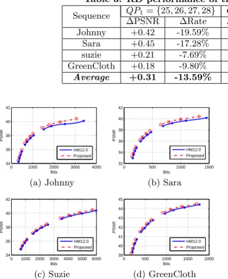
bit-rate coding configurations, respectively. Due to that our proposed method is designed for face object, firstly, we an-alyze the R-D performance of the face region in each frame (The simulation face region is shown in Figure .2). The R-D curve of the simulation results of face region for each sequences are shown in Figure .6. We can see that for all sequences with different QPs, our method gains better per-formance. The comparisons are shown in Table.3. The pro-posed scheme achieves average rate reduction of 13.59% for
QP1, 9.25% forQP2 and 9.26% forQP3 and 10.7% for all
QPs. The maximum coding gains 19.59% rate saving for
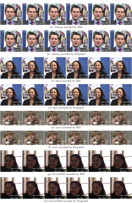
(a)Johnnyencoded by HM
(b)Johnnyencoded by Proposed
(c)Sara encoded by HM
(d)Sara encoded by Proposed
(e)suzie encoded by HM
(f)suzie encoded by Proposed
(g)GreenClothencoded by HM
(h)GreenClothencoded by Proposed
Table 3: RD performance of the proposed method (on face region)
Sequence QP1={25,26,27,28} QP2={30,31,32,33} QP3={35,36,37,38}
∆PSNR ∆Rate ∆PSNR ∆Rate ∆PSNR ∆Rate
Johnny +0.42 -19.59% +0.34 -10.59% +0.30 -7.29% Sara +0.45 -17.28% +0.44 -11.29% +0.47 -13.03% suzie +0.21 -7.69% +0.18 -6.57% +0.17 -6.01% GreenCloth +0.18 -9.80% +0.18 -8.56% +0.33 -10.72%
Average +0.31 -13.59% +0.29 -9.25% +0.32 -9.26%
0 1000 2000 3000 4000
34 36 38 40 42
Bits
PSNR
HM12.0 Proposed
(a) Johnny
0 500 1000 1500
32 34 36 38 40 42
Bits
PSNR
HM12.0 Proposed
(b) Sara
0 1000 2000 3000 4000 5000 6000
34 36 38 40 42
Bits
PSNR
HM12.0 Proposed
(c) Suzie
0 500 1000 1500 2000
39 40 41 42 43 44 45
Bits
PSNR
HM12.0 Proposed
(d) GreenCloth
Figure 6: The RD curve of test YUV sequences (on face region).
We can observe that most of frames encoded by our method consumes fewer bits and obtains higher quality.
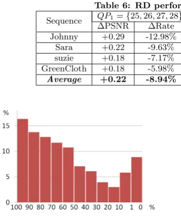
Some encoding information are analyzed in Table.5. The ex-tra bits of slice header are given in the second column. The average additional header bits using by our method is 115. Column 4 and column 5 represent the average motion vector of the face region encoded by HM and our method, respec-tively. It shows that the motion vectors get much smaller while using our method. In the third column, the usage of the additional referent picture is given. On average, 57.29% units in face region are encoded by using the new referent pictures. The distribution of usage is shown in Figure. 8. The x axis represents that how many percent of the units in a face region referent our picture. The usages on new referent picture of most face regions are more 90%. It shall be notice that some face regions have none unit using the new referent picture. For these frames, the motion vector is 0, which means the 2 adjacent frames are almost the same.
Finally, the R-D performance of the whole frames are given in Table.6. For QP1, our method achieves 8.94% rate
re-duction or 0.22 increase in PSNR. For QP2 and QP3, our
method also gets improvement. The performance of QP3
promotes small because that under the condition of low bits-rate, the total coding bits get greatly decreased and the sav-ing bits by our method also decreased, but the additional bits of slice header remain unchanged. Therefore, the total bits-rate reduction get much smaller, although the bits-rate reduction of the face region is still significant.
Table 4: Results by averaging four sequences (on face region)
QP ∆PSNR ∆Rate 25 +0.40 -16.30% 26 +0.30 -16.13% 27 +0.26 -12.40% 28 +0.30 -9.51% 30 +0.27 -9.65% 31 +0.28 -9.73% 32 +0.30 -9.71% 33 +0.28 -7.92% 35 +0.19 -8.64% 36 +0.35 -9.29% 37 +0.35 -8.49% 38 +0.39 -10.63%
Table 5: Coding information (∆B: additional bits of slice header; Usage: usage of additional referent pictures)
Sequence ∆B Usage mvHM mvProposed Johnny 111 65.29% 2.21 0.22
Sara 108 57.52% 1.23 0.15
suzie 139 44.32% 7.47 0.71 GreenCloth 103 62.02% 8.40 0.29 Average 115 57.29% 4.83 0.35
4.
CONCLUSIONS
In this paper, we proposed an improved video coding system based on HEVC for video calls. The goal of the method is to predict the face object more accurately by precessing the face region as a complete object. The complex affine trans-formations such as rotation and scaling of the face regions in nearly frames are obtained at first. Then, we create a new referent picture of the current frame and put it to the refer-ent picture list. To use the new referrefer-ent picture at decoder side, the transformation matrix needs to be writed to the bit streams. We design the procedure to keep a minimum mod-ifications to the decoder. In this paper, the improvement of the R-D performance of the proposed method is validat-ed. In the future work, the time cost by encoder should be further optimized.
5.
ACKNOWLEDGMENTS
Table 6: RD performance of the proposed method
Sequence QP1={25,26,27,28} QP2={30,31,32,33} QP3={35,36,37,38}
∆PSNR ∆Rate ∆PSNR ∆Rate ∆PSNR ∆Rate
Johnny +0.29 -12.98% +0.19 -5.73% +0.02 -0.47% Sara +0.22 -9.63% +0.07 -1.58% -0.35 +4.58% suzie +0.18 -7.17% +0.12 -4.96% +0.06 -2.34% GreenCloth +0.18 -5.98% +0.14 -4.69% +0.08 -1.88% Average +0.22 -8.94% +0.13 -4.24% -0.04 -0.02%
Figure 8: The probability distribution of usage of additional referent pictures (on face region).
6.
REFERENCES
[1] Joint video team reference software HM12.0 [online]. http://hevc.hhi.fraunhofer.de/svn/svn HEVCSoftware. [2] J. Chon, S. Whittle, E. Riskin, and R. Ladner.
Compressed video sign language conversations in the presence of data loss.Data Compression Conference, 2011.
[3] A. Glantz, M. Tok, A. Krutz, and T. Sikora. A blockadaptive skip mode for inter prediction based on parametric motion models.IEEE International Conference on Image Processing, 2011. [4] G. B. Huang, M. Ramesh, T. Berg, and
E. Learned-Miller. Labeled faces in the wild: A database for studying face recognition in
unconstrained environments.Tech. Report., U. Mass. Amherst, pages 07–49, 2007.
[5] R. C. Kordasiewicz, M. D. Gallant, and S. Shirani. Affine motion prediction based on translational motion vectors.IEEE Transactions on Circuits and Systems for Video Technology, 17(10):1388–1394, 2007. [6] F. Li and Y. Gao. Roi-based error resilient coding of
H.264 for conversational video communication.
International Wireless Communications and Mobile Computing Conference, 2011.
[7] H. Liu, D. Xu, Q. Huang, W. Li, M. Xu, and S. Lin. Semantically-based human scanpath estimation with HMMs.International Conference on Computer Vision, 2013.
[8] Y. Liu, Z. Li, and Y. Soh. Region-of-interest based resource allocation for conversational video communication of H.264/AVC.IEEE Trans on Circuits and Systems for Video Technology, 18(1):134–139, 2008.
[9] S. Milborrow and F. Nicolls. Locating facial features with an extended active shape model.European Conference on Computer Vision, 2008.
[10] D. Z. W. G. Na Zhang, Xiaopeng Fan. Motion vector derivation of deformable block.IEEE International Conference on Image Processing, 2012.
[11] Y. Peng, A. Ganesh, J. Wright, W. Xu, and Y. Ma. Rasl: Robust alignment by sparse and low-rank decomposition for linearly correlated images.IEEE Transactions on Pattern Analysis and Machine Intelligence, 34(11):2233–2246, 2012.
[12] R. Sj¨oerg, Y. Chen, A. Fujibayashi, M. M.
Hannuksela, J. Samuelsson, T. K. Tan, Y.-K. Wang, and S. Wenger. Overview of HEVC high-level syntax and reference picture management.IEEE
Transactions on Circuits and Systems for Video Technology, 22(12):1858–1870, 2012.
[13] G. Sullivan, J. Ohm, W.-J. Han, and T. Wiegand. Overview of the high efficiency video coding (HEVC) standard.IEEE Transactions on Circuits and Systems for Video Technology, 22(12):1649–1668, 2012. [14] G. Sullivan and T. Wiegand. Rate-distortion
optimization for video compression.IEEE Signal Processing Magazine, 15(6):74–90, 1998.
[15] J. Wang and M. Cohen. Very low frame-rate video streaming for face-to-face teleconference.Data Compression Conference, 2005.
[16] X. Wang, L. Su, Q. Huang, G. Li, and H. Qi. Online learning based face distortion recovery for
conversational video coding.Data Compression Conference, 2013.
[17] X. Wang, L. Su, H. Qi, Q. Huang, and G. Li. Face distortion recovery based on online learning database for conversational video.IEEE Transactions on Multimedia, 16(8):2130–2040, 2014.
[18] B. Xiong, X. Fan, and C. Zhu. Face region based conversational video coding.IEEE Trans on Circuits and Systems for Video Technology, 21(7):917–931, 2011.
[19] C. Yan, Y. Zhang, F. Dai, and L. Li. Highly parallel framework for HEVC motion estimation on many-core platform.Data Compression Conference, 2013. [20] C. Yan, Y. Zhang, F. Dai, X. Wang, L. Li, and Q. Dai.
Parallel deblocking filter for HEVC on many-core processor.Electronics Letters, 50(5):367–368, 2014. [21] C. C. Yan, Y. Zhang, J. Xu, F. Dai, J. Zhang, Q. Dai,
![Figure 3: A diagram of elements in function(3). Thetesting images are taken from the Labeled Faces inthe Wild (LFW) [4] dataset.](https://thumb-us.123doks.com/thumbv2/123dok_us/8419305.1693539/3.595.80.266.53.218/figure-diagram-elements-function-thetesting-images-labeled-dataset.webp)