http://www.sciencepublishinggroup.com/j/awcn doi: 10.11648/j.awcn.20180402.12
ISSN: 2575-5951 (Print); ISSN: 2575-596X (Online)
An Interference Coordination Scheme in Ultra-Dense
Networks Based on Power Control
Zhenchao Wang
1, 2, *, Lisha Bai
11
College of Electronic and Information Enginnering, Hebei University, Baoding, China
2College of Haibin, Beijing Jiaotong University, Cangzhou, China
Email address:
*
Corresponding author
To cite this article:
Zhenchao Wang, Lisha Bai. An Interference Coordination Scheme in Ultra-Dense Networks Based on Power Control. Advances in Wireless Communications and Networks. Vol. 4, No. 2, 2018, pp. 36-42. doi: 10.11648/j.awcn.20180402.12
Received: September 25, 2018; Accepted: October 16, 2018; Published: October 27, 2018
Abstract:
A large number of small cells are deployed in a traditional heterogeneous network to form an ultra-dense network. The ultra-dense network effectively increases the capacity of the network, but also introduces serious interference problems between low-power nodes. In order to solve the problem of downlink interference existing in the ultra-dense network, a new technical scheme based on power control (PCICS) is proposed. The PCICS scheme simultaneously determines the number of neighbor nodes around the central node and the size of the interference to the neighboring nodes as the determining node that needs to control the power. Then it translates the interference from neighboring nodes into its distance from the central node. It simplifies the method of determining the size of the interference. Then the node that meets the threshold condition is determined as the interference source node. Finally, the interference source node controls the transmission power under the condition of ensuring the normal communication of the user according to the feedback signal of the user. Therefore, the proposed solution minimizes interference to system users. Experimental data show that, compared to the TAPB algorithm, the average degree of system interference of the proposed scheme is basically the same. The average SINR is increased by 5~8dB. The average system throughput is increased by about 50%. Simulation results demonstrate that, in the case of increasing the interference source node judgment condition, the proposed scheme can effectively improve the system throughput and reduce the system power loss.Keywords:
Ultra-dense Network, Small Cell, Interference Coordination, Neighbor Node, Power Control1. Introduction
The proliferation of smart devices and wireless services has led to a new revolution of mobile communication and caused an explosion of mobile and wireless traffic volume, predicted to increase a thousand-fold over the next decades. Network scalability and efficiency are required to support a large number of devices with very low complexity [1, 2]. In order to increase the capacity of existing cellular networks, the concept of Heterogeneous Networks (HetNet) should be enhanced by ultra-dense small cell deployment in 5G network, which addresses the high traffic demands via infrastructure densification. A large number of Small Cells (SC) are deployed in the area covered by the macro base station. The ultra-dense network will become one of the key technologies for the fifth generation mobile communication technology in
transmission of the different signals on the same channel. The two kinds of interference will seriously affect the user's quality of service.
How to perform reasonable interference coordination to effectively reduce interference in ultra-dense networks has become a hot topic of research. Therefore a number of interference coordination schemes and resource allocation algorithms have been proposed. This type of solution mainly focuses on resource allocation to reduce the interference to users in the microcell by effectively allocating the resources of the base station. Such schemes are collectively referred to as enhanced inter-cell interference coordination (e-ICIC) technology in LTE-A. The use of technology is more flexible and therefore attracts more and more attention.
In the multi-cell scenario, the literature studies a resource allocation scheme combining subcarrier allocation and power control strategies [6]. This scheme minimizes the transmit power of each user on each subcarrier, and effectively reduces the interference of users in neighbor base stations, and also achieves the purpose of saving power loss. In addition, dynamic ON/OFF scheme is also an efficient scheme to eliminate interference and reduce energy consumption at the same time. In the literature of dynamic enhanced inter-cell interference coordination scheme, the author uses a combination of Grey Relational Analysis and Analytic Hierarchy Process tools to trigger the switch off actions in order to maximize the energy saving while maintaining coverage, capacity and quality [7]. The dynamic ON/OFF scheme can be considered as a binary power control solution, where the transmission power of a small cell is set to a fixed value or zero. The other literature proposes a trouble FBS-aware power back off scheme (TAPB) for the same-layer downlink interference problem [8]. The scheme determines whether power control is needed based on the number of neighbour base stations around the canter micro base station, and then effectively controls the micro base station that needs power control. This solution to a certain extent really alleviates the user's interference. However, only considering the number of neighbour micro base stations is insufficient to determine which micro base stations really need to perform power control. If the neighbour micro base stations are all located at the edge position, that is to say, the interference of the central micro base station to the neighbour micro base station is small; and it does not affect the normal communication of the user, then the micro base station does not need to control the transmission power. Once too many micro base stations control the transmit power, it may cause part of the edge users to become isolated users, thereby reducing the throughput of the network.
This paper proposes a new interference control scheme based on power control. The scheme uses the number of neighbour nodes that exist around the centre SC and the degree of interference that the centre SC generates with neighbour SC as the conditions for determining the SC that require power control. Then considering that the distance between nodes is the main factor affecting the degree of interference, the scheme adopts the idea of equivalent
transformation, and transforms the interference degree of neighbour SC from centre SC to the distance of each neighbour SC to centre SC. Finally, when the number of neighbour nodes and its distance from the central node satisfy the set threshold at the same time, the centre SC dynamically adjusts its own transmit power according to the feedback of the user. The simulation results show that the scheme achieves the purpose of reducing system interference without affecting the normal communication of the user, and improves throughput of the system at the same time, effectively solving the deficiencies in the traditional scheme.
2. System Model and Interference Source
Node Determination
2.1. UDN System Model
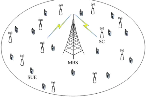
In this section, we consider a two-layer ultra-dense heterogeneous network model consisting of one MBS and many SCs. Since the network uses a scheme for different frequency deployment, only the same-layer interference problem is considered. The schematic diagram of the ultra-dense network distribution is shown as figure 1.
Figure 1. UDN distribution diagram.
The interference source SC is defined as: (1) The number of neighbour nodes around the centre SC is greater than the obtained number threshold; (2) The number of SC that the distance to the centre SC is less than the original coverage radius r of the centre SC is more than half of the total number of the neighbour SC. For convenience of description, the SC that needs power control is defined as the interference source SC.
In order to facilitate the study, this article proposes the following two assumptions:
(1)One MBS and N Small Cells are distributed in an isolated macro cell. The MBS is distributed in the centre of the macro area, and the SC is randomly distributed in the densely distributed area of the user.
the users. That is, each SC can serve any user in the cell and can provide services for up to 10 users. But each user can only choose to connect to the nearest SC. There is no isolated user in the network.
2.2. Neighbor Discovery
The number of neighbour SCs that exist around the central SC is an important factor that affects the degree of interference to users. With the increase of the number of neighbouring SCs around the centre SC, users are experiencing more and more interference. Within a certain range, the SC can search for the number of neighbouring SCs by sending data packets. This article uses the neighbour search method to expand the search range by temporarily changing the transmit power of the SC [8]. This will ensure a more accurate search plan.
Figure 2. Neighbor relationship diagram of SC.
After the central node establishes a neighbour relationship, it obtains a neighbour relationship diagram, as shown in figure 2. The outer dotted line indicates the coverage after the increase of the transmission power.
The specific steps for the neighbour SC search solution are as follows.
Step 1 First of all, each of the SC increases its own transmit power so that the radius of the circular coverage area becomes twice the original (which is2r), and then the SC sends Hello packets to other Small Cells in its coverage area.
Step 2 Then, each SC counts the number of Hello packets received from other Small Cells, constructs its own neighbour list, and obtains the number B ii( ∈{1, 2⋯N})of neighbour SC.
Step 3 Determine the number of neighbour SC. Calculate the average number of neighbour SC according to equation (1).
1
N i i B A
N
=
=
∑
(1)Then the system uses the average and the formula (2) to calculate the standard deviation SD,
2
1( )
N i
i A B
SD
N = −
=
∑
(2)The threshold for determining the number of neighbour SC required is determined according to formula (3). Where n is a multiple impact factor.
* l b
TN = +A SD n (3)
Step 4 Compare the number of neighbour SC and the size of the obtained threshold. If the number of neighbour SC is greater than TNib , then the next condition is judged. Otherwise, it directly determines that the central SC is not the interference source SC.
2.3. Interference Analysis Based on the Distance Between the Nodes
This article only analyses the same downlink interference between SC. The schematic diagram of the same-layer interference in the downlink of the ultra-dense network is shown in figure 3. The distance between nodes is the main factor affecting the degree of interference between nodes. The analysis of the interference between the nodes is converted into the analysis of the distance between nodes. The closer the distance between the nodes, the more serious the interference is to the corresponding users. On the contrary, the interference will be even smaller.
Figure 3. The same-layer downlink interference map in UDN.
1
( )
2 i
d = ⋅ ⋅ − ∆c t t (4)
Take the neighbour relationship established in figure 2 as an example. A distance analysis is performed on the neighbour SC whose number of neighbouring SC satisfies a threshold condition around the central SC.
Step 1 First, the central node SC0 calculates the distance
from SC0 to neighbour SC1⋯SC8 respectively. And the
resulting distance is arranged in descending order, which is obtained in turnd d1, 2,⋯d8;
Step 2 The median value of the distances in descending order is obtained according to formula (5). In figure 2, it sets
8
n= . So that the median value is 4 5
2
d d
d = + ;
+1 2
1
2 2
, is an odd number.
, is an even number. 2
n
n n
d n
d d d
n + = + (5)
Step 3 Compare the median of distance d with the radius R of the original coverage area of SC0 . When d<r , it
indicates that the number of neighbour SC in the original coverage of the central node SC0 is more than half of the
total number of neighbour nodes. In other words, the neighbour SC meets two constraints at the same time. It can be determined that the central SC0 is an interference source
node.
3. PCICS Interference Coordination
Scheme
Part 2 of this article identifies two conditions for determining the source SC. That is, the number of neighbour SC and the distance of neighbouring SC from the central SC. The interference source SC is determined based on these two determination conditions. Finally, a dynamic power control strategy is adopted for the interference source SC. Finally, the purpose of mitigating the interference of the source SC to the neighbour SC is reduced.
3.1. Power Control
The power control strategy is one of the LTE-A heterogeneous network interference coordination technologies[9-11]. Its main idea is to dynamically adjust the size of the micro base station transmission power according to the user's feedback signal, so as to achieve the purpose of reducing the interference to users in the surrounding cells. After the interfering source node decision phase in the second part of this article is completed, the SC recovers to normal transmit powerP0. Then each of the Small Cells establishes a
connection with a user (SUE) within its coverage area. The SUE sends the received signal strength (RSS) to its
corresponding SC (including the interference source SC), and the SC establishes a user received signal strength table to prepare for the next power control scheme.
In the power control stage of the interference source SC , its transmission power needs to be properly reduced. It is expected that normal communication with the SUE can be performed under the condition of ensuring the minimum RSS. Implementing a power control strategy on the aggressor SC will reduce the coverage area of the SC. However, whether the SUEj is in the original coverage area or in the coverage area
that the transmission power is reduced, the signal strength of the SUEj receiving from the SCi must be at least R0.
Without power control, SCisends a signal at powerPi. The signal experiences a path loss before it is received by the user
SUEj. The power Rijfrom the SCi received by the user
SUEjis given by equation (6), where the path loss between
SCi and SUEj is Lij.
[ ] [ ] [ ]
ij i ij
R dBm =P dBm −L dB (6)
After the power control phase is completed, Rijis made
equal to the minimum power R0 required for normal
communication between the SC and the SUE .
0( ) i( ) ij( )
R dBm =P dBm −L dB (7)
Let C ii( ∈{1, 2⋯N}) be the set of users for the SCi services and Pi be the transmit power ofSCi . In the conventional model of operation with no power control (Legacy No Power Control, LNPC), all Small Cells transmit with the nominal powerP0. After the aggressor SC reduces the
transmission power, it should be guaranteed that it can still serve all SUEs in the original service range. As far as possible, it should ensure that not any SUE becomes an isolated user due to node power control. Therefore, formula (8) can be obtained.
0
0 0 ,
( min∈ ( )) ,
<
=
+ − ≥ <
j
i lb
i
j C i j i lb
P B TN
P
P R R B TN d r (8)
Let
γ
j be the signal to noise ratio of the user and Sjthesignal received by the user SUEj from the SC. The total
interference of SUEj is Ij. Then the SINR of the user can be obtained.
10
[ ] [ ] 10 log (noise( ) ( ))[ ]
j dB S dBmj mW I mWj dBm
γ = − + (9)
It is assumed that the strongest received signal strength RSS of SUEj in formula (10) is Sj. Therefore, the rest part is the total interference received.
1
max
j i N ij
1 1
max N
j ij i N ij
i
I R ≤ ≤ R
=
=
∑
− (11)This paper selects the 3GPP Typical Urban model with shadowing as the path loss model. dij is the distance between SCi and SUEj. The path loss can be expressed as formula (12).
10
127 30 log ( )
ij ij g
L = + d +X (12)
Where Xg accounts for the shadowing and has a log
normal distribution lnN(0,
σ
2). After the signal to noise ratio SINR of the user is obtained, the capacity C is calculated using the SINR as a CQI (CQI-Channel Quality Indicator)[12].In this paper, the number of nodes for power control is reduced by increasing the judgment conditions of the interference source node. The transmission power of the node is increased under the condition that the system user interference is basically unchanged. According to the Shannon
formula 2
1
log (1 ) n
i
i i
S C
N
=
=
∑
+ , it can be concluded that thescheme improves the system capacity.
3.2. The PCICS Program Execution Steps
Step 1 First, the SCs in the area increase their own transmission power, so that the radius of the original coverage area is doubled. Then each of the SCs sends Hello packets to other SCs in the new coverage area.
Step 2 According to the search scheme in the second part of this article, the neighbour SC is searched. Then each SC establishes its own neighbour relationship list and obtains the number Bi of neighbour SCs.
Step 3 Under the condition that the number of neighbour SC meets the threshold, the central SC obtains the distance from each neighbouring SC to it. The central SC determines whether it is the interference source SC according to the judgment condition of the second part of the article.
Step4 After the interference source SC decision phase is completed, each SC recovers to its normal transmit power. In addition, the SUE establishes connections with the SUEs in the respective coverage areas. The SUE sends feedback RSS to the SC. The interference source SC performs power control according to the RSS and ensures that no isolated users are generated.
4. Simulation Results and Discussion
In this section, the system level simulation results are presented to illustrate the benefits of the proposed PCICS scheme. In order to verify the effectiveness of the proposed project, the performance for the traditional powerless control program (LNPC) and the TAPB algorithm and the proposed interference coordination program based on power control (PCICS) is simulated using Matlab simulation experiment
platform. With the same simulation environment and parameters, the experimental results under the three different algorithms were compared and analysed.
4.1. Simulation Test-bed Setup
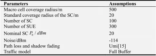
In the system simulation, the macro base station and the micro base station operate in different frequency bands, so there is only the same-layer interference between the micro base stations. The simulation parameters mainly refer to the LTE-A standard [13, 14]. The system bandwidth is considered to be 10 MHz, and the centre frequency of the macro base is 2.3 GHz. The centre frequency of the small cell is 3.5GHz. In a circular area with a radius of 500 meters, 100 SCs and 300 SUEs are randomly distributed. The initial transmission power of the SC is P0. Each SC can serve a maximum of 10 SUEs.
Each SUE can only be served by one SC. When one SC serves multiple SUEs, the entire resource block is evenly distributed to each user. If there are additional resource blocks, they are assigned to the users with the best SINR. The system bandwidth in this paper is set to 10 MHz, corresponding to 50 resource blocks in the frequency domain. The standard coverage radius of the SC is 20m, and the distance between the two SCs is at least 5 meters. This paper uses the 3GPP Typical Urban shadowing model as the path loss model. Simulation parameters are shown in the Table 1. In order to reduce the random error, the simulation time is set to 60s. Under the premise that other conditions are not changed, the system randomly changes the deployment position of SCs for 20 times. And each of deployment methods is repeated for 100 times. Then the average of 100 simulation results is taken as the final simulation result.
Table 1. Simulation parameters.
Parameters Assumptions
Macro cell coverage radius/m 500
Standard coverage radius of the SC/m 20
Number of SC 100
Number of SUE 300
Nominal SCP0/dBm 20
Noise/dBm -114
Path loss and shadow fading Umi[15]
Traffic model Full Buffer
4.2. Results Analysis
In the above simulation environment, only the deployment position of the SC is changed, and the average interference and average throughput of the 300 SUEs in the network are analysed. The simulation results are shown in figure 4 figure 5 and figure 6.
the number of SCs for power control, but it does not increase the interference of the system users. The average interference of the system is not much different from the TABP algorithm and it is within the acceptable range.
Figure 4. System average interference comparison chart.
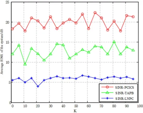
The figure 5 depicts a comparison of the average user signal-to-noise ratio of the system under different scenarios as a function of SC deployment. The signal to interference and noise ratio is defined as the ratio of the user's strongest acceptance of the signal strength RSS to the sum of the interference and noise. It can be seen from the figure that when the number of SCs is set to 100, the SINR of the three schemes fluctuates to some extent as the SC deployment position changes. However, the PCICS scheme proposed in this paper has the highest signal-to-noise ratio, which is about 14dB higher than the LNPC scheme and about 8dB higher than the TAPB. This clearly shows the superiority of the proposed scheme.
Figure 5. System average SINR comparison chart.
Under the condition that the number of users remains unchanged, figure 6 describes the situation where the average throughput of the system changes with the change of the SC
deployment location. The figure compares the average throughput of the system under the LNPC scheme, the TAPB algorithm, and the PCICS scheme proposed in this paper. It can be clearly seen from the figure that compared with the LNPC scheme; the TABP algorithm and the PCICS scheme all increase the average throughput of the system to different degrees. Although the PCICS scheme reduces the number of power-controlled SCs, it increases the coverage area of the nodes and reduces the number of blind-spot users. Compared with the TABP algorithm, the proposed scheme obviously increases the throughput of the system by 50%. This confirms the effectiveness of the proposed scheme once again.
Figure 6. System average throughput comparison chart.
5. Conclusion
Acknowledgements
This work has been supported by the Natural Science Fund Project of Hebei Province under Grant F2014201168.
References
[1] Fratu O, Vulpe A, Craciunescu R, et al. Small Cells in Cellular Networks: Challenges of Future HetNets [J]. Wireless Personal Communications, 2014, 78(3):1613-1627.
[2] Cosovic M, Tsitsimelis A, Vukobratovic D, et al. 5G Mobile Cellular Networks: Enabling Distributed State Estimation for Smart Grids [J]. IEEE Communications Magazine, 2017, 55(10):62-69.
[3] Chandrasekhar V, Andrews J G. Spectrum allocation in tiered cellular networks [J]. IEEE Transactions on Communications, 2009, 57(10):3059-3068.
[4] Uygungelen S, Bauch G, Taoka H, et al. Protection of Cell-Edge Users in Wireless Systems by Using Almost Blank Subframes[C]// International Itg Conference on Systems, Communication and Coding. VDE, 2013:1-6.
[5] Ozawa M, Ohtsuki T. Improvements of femtobase station resource utilisation and ABS assignment convergence for dynamic ABS assignment [J]. Iet Communications, 2017, 11(3):370-376.
[6] Ming Gong, Pin-Han Ho, Chih-Hao Lin. A coordinated multi-point-based quality of service provision resource allocation scheme with inter-cell interference mitigation [J]. Wireless Communications and Mobile Computing, 2016, 16(6): 656-668.
[7] Huang Peng, Huang Chen, Huang Peng, Huang Chen, Liao Xinqi, et al. Dynamic Enhanced Inter-cell Interference Coordination Scheme Based on Power Control in HetNet [J]. Computer Engineering, 2016, 42(12): 102-107, 111.
[8] Wang H C, Woungang I, Ting K C, et al. Co-tier downlink interference management in dense femtocell networks [J]. International Journal of Communication Systems, 2016, 29(17):2534-2541.
[9] Hang Chen. Research on Interference Coordination Algorithm for 5G Dense Networks [D]. Chongqing University of Posts and Telecommunications, 2016.
[10] Gong Shengli, Jin Yong. Joint transmission-based clustering and power allocation algorithm in femtocell networks [J/OL]. 2018, 35(10).
http://www.arocmag.com/article/02-2018-10-060.html. [11] Zhang Xin, Jin Chunfeng, Zhang Yan. Power control algorithm
based on resource allocation in heterogeneous networks [J]. Computer engineering and design, 2017, 38(6):1446-1451. [12] Ericsson LTE KPI throughput calculator, CQI table.
[13] Wang Juncai, Liu Tingting, Yang Chenyang, et al. Predictive Resource Allocation to Maximize the Throughput of Ultra-Dense Networks [J]. Journal of signal processing, 2017, 33(3):260-267.
[14] Huang C, Chen Q, Tang L. Hybrid inter-cell interference management for ultra-dense heterogeneous network in 5G [J]. Science China Information Sciences, 2016, 59(8):082305. [15] ITU-R, (2009) Guidelines for Evaluation of Radio Interface