Volume 2007, Article ID 69805,9pages doi:10.1155/2007/69805
Research Article
Progressive Image Transmission Based on
Joint Source-Channel Decoding Using Adaptive
Sum-Product Algorithm
Weiliang Liu1, 2and David G. Daut1
1Department of Electrical and Computer Engineering, Rutgers, The State University of New Jersey,
Piscataway, NJ 08854, USA
2Qualcomm Inc., San Diego, CA 92121, USA
Received 13 August 2006; Revised 12 December 2006; Accepted 5 January 2007
Recommended by B´eatrice Pesquet-Popescu
A joint source-channel decoding method is designed to accelerate the iterative log-domain sum-product decoding procedure of LDPC codes as well as to improve the reconstructed image quality. Error resilience modes are used in the JPEG2000 source codec making it possible to provide useful source decoded information to the channel decoder. After each iteration, a tentative decoding is made and the channel decoded bits are then sent to the JPEG2000 decoder. The positions of bits belonging to error-free coding passes are then fed back to the channel decoder. The log-likelihood ratios (LLRs) of these bits are then modified by a weighting factor for the next iteration. By observing the statistics of the decoding procedure, the weighting factor is designed as a function of the channel condition. Results show that the proposed joint decoding methods can greatly reduce the number of iterations, and thereby reduce the decoding delay considerably. At the same time, this method always outperforms the nonsource controlled decoding method by up to 3 dB in terms of PSNR.
Copyright © 2007 W. Liu and D. G. Daut. This is an open access article distributed under the Creative Commons Attribution License, which permits unrestricted use, distribution, and reproduction in any medium, provided the original work is properly cited.
1. INTRODUCTION
Progressive coded images, such as those compressed by wa-velet-based compression methods, have wide application in-cluding image communications via band-limited wireless channels. Due to the embedded structures of the correspond-ing compressed codestreams, transmission of such images over noisy channels exhibits severe error sensitivity and al-ways experiences error propagation. Forward error correc-tion (FEC) is a typical method used to ensure reliable trans-mission. Powerful capacity-achieving channel codes such as turbo codes and low-density parity-check (LDPC) codes have been used to protect the JPEG2000 codestream using various methods [1–3]. The typical idea of these schemes is to assign different channel protection levels via joint source-channel coding (JSCC) based on a rate distortion method. In addition to JSCC systems that are designed at the transmitter/encoder side, researchers also find that joint source-channel decoding (JSCD) can be achieved at the re-ceiver/decoder side. The concept of utilizing source decoded
(LDPC) codes [13,14], they had been quickly adopted for many applications including image transmission. LDPC iter-ative decoding behavior has been studied in [15–17]. In [18], a JSCD method for JPEG2000 images has been proposed us-ing a modification algorithm similar to that in [12].
In this paper, we develop a JSCD method for JPEG2000 image transmission on both AWGN and flat Rayleigh fading channels. Fading channels wherein the receiver either has, or does not have additional channel state information (CSI) are considered. A regular LDPC code is used as the error cor-recting code. Log-domain iterative sum-product algorithm is chosen as the channel decoding method. After each iter-ation of the log-domain sum-product algorithm, the source decoder provides useful information as feedback that is based on the error resilience modes employed in the source codec. The information is then used to modify the log-likelihood ra-tio (LLR) of the corresponding bit nodes. The new modifica-tion factor presented in this paper extends the idea previously investigated in [12,18]. Results show that the new scheme can accelerate the iterative sum-product decoding process as well as improving the overall reconstructed image quality.
The outline of this paper is as follows.Section 2presents the sum-product algorithm and some observations about its iterative behavior. JPEG2000 and its error resilience capa-bility are first described inSection 3followed by the design of the joint source-channel decoding algorithm. Section 4
presents selected simulation results. Conclusions are given in
Section 5.
2. SUM-PRODUCT ALGORITHM AND ITS ITERATIVE BEHAVIOR
The iterative sum-product algorithm for LDPC decoding in the log-domain is first introduced in this section. Both the AWGN channel and the flat Rayleigh fading channels with and without CSI are considered. The corresponding behav-iors of the iterative algorithm are described in the second part of this section.
2.1. Log-domain sum-product algorithm
Consider anM×Nsparse parity check matrixH, whereM=
N−K.Nis the length of a codeword, andKis the length of the source information block. An example ofHis shown as
H=
⎡ ⎢ ⎢ ⎢ ⎢ ⎢ ⎣
1 1 0 1 1 0 1 0 1 0 0 1 1 0 0 1 1 0 1 1 0 1 0 1 1 1 0 1 0 1 1 0 1 0 1 1 0 1 1 0 1 0 1 1 0 0 1 1 0 1 ⎤ ⎥ ⎥ ⎥ ⎥ ⎥
⎦. (1)
The sparse matrix H has an equivalent bipartite graph de-scription called a Tanner graph [19].Figure 1shows the Tan-ner graph corresponding to (1). In the graph, each column (row) ofHcorresponds to a bit node (a check node). Edges connecting check and bit nodes correspond to ones inH. In this example, each bit node is connected by 3 edges and each check node is connected by 6 edges. Therefore, each column ofHcorresponds to a bit node with weight 3 and each row of
Check nodes
m1 m2 m3 m4 m5
n1 n2 n3 n4 n5 n6 n7 n8 n9 n10 rx
mn
qx nm
Bit nodes
Figure1: An example of Tanner graph corresponding to the matrix Hin (1).
Hcorresponds to a check node with weight 6. A detailed iter-ative sum-product decoding algorithm is presented in [20]. In order to reduce the computation complexity and the nu-merical instability, a log-domain algorithm is preferred. It is introduced briefly as follows.
The message rx,l
mn, the probability that bit node n has
the valuexgiven the information obtained via all the check nodes connected to it other than check node mfor the lth iteration, is passed from check nodes to bit nodes. Simi-larly, the dual messageqx,l
nmis passed from bit nodes to check
nodes. Here, x is either 1 or 0. We define a set of bitsn that participate in check m asN(m) = {n : Hmn = 1} and define a set of checksmin which bitnparticipates as M(n)= {m:Hmn =1}. NotationN(m)\ndenotes a set N(m) with bitnexcluded and notationM(n)\mdenotes a setM(n) with checkmexcluded. The algorithm produces the LLR of thea posterioriprobabilities for all the codeword bits after a certain number of iterations.
Consider an AWGN channel with BPSK modulation that maps the source bitcto the transmitted symbolxaccording tox=1−2c. The received signal is modeled as y=x+nw with the conditional distribution
p(y|x)=√ 1 2πσ2exp
−(y−x)2
2σ2 , (2)
wherenwis white Gaussian noise with varianceσ2=1/2·R·
(Eb/N0), andRis the channel code rate. At the initial step, bit
nodesnhave the values given by
Lcn=Lq0nm=log
Pcn=0|yn
Pcn=1|yn
= 2
σ2·yn. (3)
Denote the corresponding LLR of the messagesqx,l
nmandrmnx,l
asLqnml = log(q0,l
nm/qnm1,l) andLrmnl = log(rmn0,l/rmn1,l),
respec-tively. Before the first iteration, Lq0
nm is set to Lcn. By
de-noting Lqlnm = αl
nm·βlnm, where αlnm = sign(Lqlnm) and
βl
nm = abs(Lqlnm), the first and the second parts of one
it-eration are
Lrl mn=
n∈N(m)\n
αl nm
·Φ
n∈N(m)\n Φβl
nm
, (4)
Lql
nm=Lcn+
m∈M(n)\m
Lrl
where Φ(x) = −log(tanh(x/2)) = log((ex+ 1)/(ex−1)). The LLR of “pseudoposteriori probability” defined asLQnl= log(Q0,l
n/Q1,nl) is then computed as
LQl
n=Lcn+
m∈M(n) Lrl
mn. (6)
The following tentative decoding is made:cl
n = 0 (or 1) if
LQl
n>0 (or<0). WhenLQnl=0,cnlis set to 0 or 1 with equal
probability. In theory, whenHcl
n=0, the iterative procedure
stops.
2.2. Decoding in the case of fading channels
For wireless communication, Rayleigh fading channel is typ-ically a good channel model. Consider an uncorrelated flat Rayleigh fading channel. Assume that the receiver can esti-mate the phase with sufficient accuracy, then coherent de-tection is feasible. The received signal is now modeled as
y=ax+nw, wherenwis white Gaussian noise as described in the previous subsection. The parameter a is a normal-ized Rayleigh random variable with distribution PA(a) = 2a·exp(−a2) andE[a2]=1. Assume that the fading
coef-ficients are uncorrelated for different symbols. BPSK mod-ulation maps the source bit cto the transmitted symbolx according tox =1−2c. At the initial step, the bit nodesn take on the values
Lcn=log
Pcn=0|yn
Pcn=1|yn
=2a
σ2 ·yn. (7)
The message definition above implies that the receiver has perfect knowledge of the CSI. For the case when CSI is not available at the receiver,E[a]=0.8862 can be used instead of the instantaneous valueain (3). Thus, the bit nodesntake on the values
Lcn=log
Pcn=0|yn
Pcn=1|yn
=2Eσ[2a]·yn. (8)
For each iteration thereafter, the relationships given in (4)– (6) are used once again without any changes.
2.3. Behavior of the sum-product algorithm
As mentioned above, onceHcn=0, the iterative procedure
stops. However, a large number of iterations may be needed to meet this criteria. Also, there is no guarantee that the it-erative procedure converges unless the codeword length is infinite. In real-world applications, there exist three imple-mentation problems: (1) finite block lengths (e.g., 103–104)
are used; (2) the sum-product algorithm is optimal in the sense of minimizing the bit error probability for a cycle-free Tanner graph. For finite length codes, the influence of cycles cannot be neglected; and (3) the maximum number of itera-tions is always preselected before communication takes place. The preselected iteration number is usually smaller (e.g., 40– 60) compared to the number that is needed to satisfy the strict stopping criteria. Examples are presented in the follow-ing to illustrate the iterative behavior of LDPC codes. A reg-ular (4096,3072) LDPC code with rate 3/4 is selected. The
0 10 20 30 40 50 60 70
0 100 200 300
0 10 20 30 40 50 60 70
0 100 200 300
0 10 20 30 40 50 60 70
0 100 200 300
0 10 20 30 40 50 60 70
0 100 200 300
0 10 20 30 40 50 60 70
0 100 200 300
0 10 20 30 40 50 60 70
0 100 200 300
Number of iterations
Hi
st
o
gr
am
s
Figure2: Histogram for number of iterations for the log-domain sum-product algorithm over AWGN channel. (γ=2.50 to 3 dB in increments of 0.1 dB, from top to bottom.)
log-domain decoding procedure is performed for a total of 1000 transmission trials. The maximum number of channel decoder iterations is set to 60 for each trial. Two channels are tested, one is the AWGN channel and the other is the flat fading channel with CSI. Figures2and3show the his-tograms of the iteration numbers versusγ=Eb/N0and the
averageEb/N0,γ. Thex-axis represents the number of
itera-tions needed for each LDPC decoding trial. They-axis repre-sents the number of occurrences (out of 1000 experiments) of a certain number of iterations. The figures illustrate that with increasingγandγ, the overall histogram becomes more and more narrow. This means that the decoding time reduces when better channel conditions are realized. Another point of observation obtained from these figures is that of the bars located at the maximum number of iterations, 60. For an AWGN channel, operating atγ=2.5 dB, there are about 100 out of 1000 times that the decoding procedure does not sat-isfyHcn=0, and has to abruptly stop. With increased
chan-nel SNR, this number becomes 31, 12, and 2 atγ=2.6, 2.7, and 2.8 dB, respectively. The number of times the maximum is needed becomes zero as the channel condition continues to improve. Similar observations are also found for the fad-ing channel. InFigure 3, operating atγ=6.55 dB, there are about 36 decoding procedures that do not satisfyHcn = 0
and have to stop. This number becomes 6 atγ = 6.75 dB. Reducing the number of decoding failures indicates that the performance of the code becomes increasingly better.
0 10 20 30 40 50 60 70 0
100 200
0 10 20 30 40 50 60 70
0 100 200
0 10 20 30 40 50 60 70
0 100 200
0 10 20 30 40 50 60 70
0 100 200
0 10 20 30 40 50 60 70
0 100 200
Number of iterations
Hi
st
o
gr
am
s
Figure3: Histogram for number of iterations for the log-domain sum-product algorithm over flat fading channel with CSI. (γ=6.55 to 6.75 dB in increments of 0.05 dB, from top to bottom.)
4 6 8 10 12 14 16 18 20 22
2.5 2.6 2.7 2.8 2.9 3 3.1 3.2 3.3 3.4 3.5 Eb/N0(dB)
N
u
mber
of
it
er
ations
Mean Median
Figure 4: Mean and median number of iterations over AWGN
channel.
values of the median have a property similar to a nonincreas-ing function. The mean and median are two important statis-tics that better measure the number of iterations needed dur-ing the decoddur-ing process.
The decoder iteration behaviors described above provide some insight for practical design considerations. It is desired to establish a JSCD methodology that has the capability to update the messages that are passing back and forth between the bit and check nodes during the iterations. Furthermore, such updated information should come from outside of the
10 12 14 16 18 20
6.4 6.6 6.8 7 7.2 7.4 7.6 7.8 8 AverageEb/N0(dB)
N
u
mber
of
it
er
ations
Mean CSI Median CSI
Mean no CSI Median no CSI
Figure5: Mean and median number of iterations over flat Rayleigh fading channel with and without CSI.
LDPC decoder as extrinsic information similar to that which is exchanged between the constituent convolutional decoders within an iterative turbo decoder.
3. JOINT SOURCE-CHANNEL DECODER DESIGN
A natural choice for the provider of the extrinsic informa-tion is the source decoder that follows the channel decoder. In this paper, the JPEG2000 decoder after the LDPC decoder can provide such extrinsic information. The error resilience tools provided in the JPEG2000 standard are discussed in the first part of this section. In the second part, the details of the JSCD design are provided.
3.1. Error resilience methods in JPEG2000
Packet 1
Packet 2 . . .
Packet 6
Packet
7 . . . Packet
8
Packet 12
Packet 13
Packet 14 . . .
Packet 18
Layer 1 Layer 2 Layer 3
HL LH HH HL LH HH HL LH HH
9 useful coding passes will be updated 6 coding passes will stay unchanged E X X X X X
Figure6: Error resilience mechanism used in JPEG2000 to prevent error propagation.
and will not be propagated to other codeblocks in the trans-mitted data stream.
3.2. Adaptive modification in the joint design
From the channel decoder point of view, the error resilience mechanism implemented in the source decoder may provide potential feedback information that makes it possible to de-sign a joint source-channel decoder. In [12,18], two diff er-ent modification methods have been proposed. The former one either enlarges or reduces the extrinsic information in turbo codes by the mappings x = x·t or x = x/t, re-spectively, wheretis the modification factor whose value de-pends on the channel conditions. The latter one uses a simple plus or minus operation to modify the LLR values in LDPC codes as x = x +t or x = x −t. We note here, most importantly, thattis channel-independent. As discussed in
Section 2, the behavior of the iterative decoding algorithm is
channel-dependent. Hence, a channel-adaptive modification algorithm is expected to be more beneficial both in the re-duction of computation time and the improvement in over-all image quality. Since the log-domain is used in the sum-product algorithm, using plus and minus operations to in-crease and dein-crease the LLR values coincides with the prod-uct and division algorithms in the probability domain.
The proposed joint decoder block diagram is illustrated
inFigure 7. It operates as follows: the parts in the dashed line
frame represent a typical log-domain iterative sum-product LDPC decoder. After theith iteration, the JPEG2000 decoder receives the tentative decoded bits ci
n. Only several initial
JPEG2000 decoding steps will be executed. The aim is to find which coding pass contains the first bit error within a code-block. The whole JPEG2000 decoding procedure will not be applied at this time. Compared to an iteration of LDPC decoding, such an operation is very quick. In the example shown inFigure 6, the 10th coding pass contained the first bit error. The JPEG2000 decoder then feeds the positions of bits
Pi, which belong to the useful coding passes (the first 9 useful
coding passes inFigure 6), back to the channel decoder. The
Lcnvalues corresponding to those positions will be updated
and denoted asLci,new
n . At the same time, the LLR values of
the last 6 coding passes will remain unchanged. The adaptive
Iterative LDPC decoder
Check nodes Bit nodes From
channel Tentative
decoding/ decision Adaptive
modification JPEG2000
decoder Lqi
nm
LQni
Lcn Lrmni
Lci,new
n
Pi c i n
Ii
Figure7: Block diagram of the joint source-channel decoder.
modification methods will be discussed later. At the initial step,Lcn is calculated using (3), (7), or (8), and after that, for each iteration, it will be updated asLci,new
n and sent to the
bit nodes. Bit nodes then useLci,new
n to compute the second
part of the iteration corresponding to (5) and the tentative decision. When the iterative procedure stops, the JPEG2000 decoder reconstructs the entire imageIias the system output. Thus, the modification factort(·) used in the algorithm is de-signed so as to be a function of the channel condition. Hence, the desired parameter ist(γ), withγbeing the channel SNR in terms ofEb/N0. A similar approach can be used in
con-nection with flat fading channels. Using the average channel SNR,γ,t(·) is designed to bet(γ,a) andt(γ,E[a]) for fading channels with CSI and without CSI, respectively. Then, the modification algorithm after each iteration is defined as
Lci,new
n =
⎧ ⎪ ⎪ ⎪ ⎨ ⎪ ⎪ ⎪ ⎩
Lci−1,new
n +t(·) ifcni−1=0;n∈Pi−1,
Lci−1,new
n −t(·) ifcni−1=1;n∈Pi−1,
Lci−1,new
n ifn /∈Pi−1,
(9)
where
t(·)= ⎧ ⎪ ⎪ ⎨ ⎪ ⎪ ⎩
t(γ) for AWGN Channel,
t(γ,a) for flat fading channel with CSI,
At the initial iteration,Lc0,new
n = Lcn.Piis a set of bits that
belongs to the correct coding passes for theith iteration ob-tained from the JPEG2000 decoder. TheLci−1,new
n values
asso-ciated with thePibits are either plus or minus a modification factort(·) so as to generate new LLR values. Bits that are not in the setPihold onto their last iteration values without any update. Further, since the fading coefficientaattenuates the transmitted symbolx, it is worthwhile to compensate fora in the case of those bits that belong toPi. Thus, the modifi-cation factors can be written ast(γ)/aandt(γ)/E[a], respec-tively. Botht(γ) andt(γ) can be tabulated empirically before beginning real-time transmission of compressed image data.
4. SELECTED SIMULATION RESULTS
The proposed JSCD method and the associated modification algorithm have been simulated. The 8-bit gray-scale Lena im-age was used. Three source coding rates 1.0, 0.5, and 0.1 bpp were selected. For each rate, three quality layers were gener-ated. A (4096, 3072) regular LDPC code with rate 3/4 was employed in the system. The maximum number of iterations was set to 60. For AWGN and flat fading channels (assume uncorrelated Rayleigh fading), different sets ofγorγwere se-lected so that the performances of the LDPC code are close to each other under these channel conditions for different chan-nel models. For each chanchan-nel condition, the corresponding BER performance is presented inTable 1.
For a source coding rate of 0.5 bpp, Tables2–4 present the simulation results for the AWGN channel and flat fad-ing channels with and without CSI. In each table, the second column shows the values oft(γ) andt(γ). The quantityt(γ) is divided by eitheraorE[a] for channels with or without CSI to form the modification factors, respectively. The last two columns show the PSNR (dB) and mean number of iter-ations in pairs corresponding to without/with use of a joint decoding strategy.
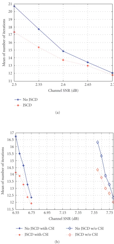
Data in the three tables are plotted in Figures8 and9.
Figure 8illustrates the mean number of iterations for
sys-tems employing a JSCD design as well as for syssys-tems not using a joint decoding design. It is obvious that for all the channel models, the JSCD system requires less decoder it-eration, which means that the overall decoding time can be reduced. For an AWGN channel, the decoding time can be reduced by as much as 2.16% to 16.93%. The decoding time is reduced by 2.43% to 15.42% for the fading channel case.
Figure 9shows the qualities of the reconstructed images both
with a JSCD design and without a joint decoding design em-ployed at the receiver. In all the channel models, the PSNR gain becomes smaller with an increase in the channel SNR. Also,Figure 9shows that the JSCD method is more effective for the fading channel with CSI than that for the fading chan-nel without CSI. That is due to the fact thatE[a] is not a suf-ficient statistic compared to the instantaneous fading coeffi -cienta. It has been found that a gain of 1.24 dB to 3.04 dB can be obtained on an AWGN channel employing a JSCD design for image transmission, while for a fading channel, the gain in PSNR is up to 2.52 dB when CSI is available. Simulation results illustrating the PSNR gain for the other two source
11 12 13 14 15 16 17 18 19 20 21
2.5 2.55 2.6 2.65 2.7
Channel SNR (dB)
M
ean
of
n
u
mber
of
it
er
ations
No JSCD JSCD
(a)
11.5 12 12.5 13 13.5 14 14.5 15 15.5 16 16.5 17
6.55 6.75 6.95 7.15 7.35 7.55 7.75 Channel SNR (dB)
M
ean
of
n
u
mber
of
it
er
ations
No JSCD wtih CSI JSCD with CSI
No JSCD w/o CSI JSCD w/o CSI (b)
Figure 8: Mean number of iterations with and without using a JSCD design. Source coding rate at 0.5 bpp (a) for AWGN channel, (b) for flat fading channels with and without CSI.
coding rates 0.1 bpp and 1.0 bpp are presented in Figures10
and11. The results are similar to the case of 0.5 bpp.
5. CONCLUSION
Table1: Channel SNR sets and the corresponding BER performance.
AWGN 2.50 2.55 2.60 2.65 2.70
BER 2.4×10⁻³ 1.26×10⁻³ 5.90×10⁻⁴ 2.37×10⁻⁴ 1.90×10⁻⁴
Fading CSI 6.55 6.60 6.65 6.70 6.75
BER 1.03×10⁻³ 7.94×10⁻⁴ 5.03×10⁻⁴ 2.71×10⁻⁴ 1.89×10⁻⁴
Fading no CSI 7.60 7.65 7.70 7.75 7.80
BER 1.22×10⁻³ 7.87×10⁻⁴ 4.78×10⁻⁴ 3.10×10⁻⁴ 2.19×10⁻⁴
16 17 18 19 20 21 22 23 24 25 26 27 28 29
2.5 2.55 2.6 2.65 2.7
Channel SNR (dB)
PSNR
(dB)
No JSCD JSCD
(a)
18 19 20 21 22 23 24 25 26 27 28 29
6.55 6.75 6.95 7.15 7.35 7.55 7.75 Channel SNR (dB)
PSNR
(dB)
No JSCD wtih CSI JSCD with CSI
No JSCD w/o CSI JSCD w/o CSI (b)
Figure9: PSNR with and without using a JSCD design. Source cod-ing rate at 0.5 bpp (a) for AWGN channel, (b) for flat fadcod-ing chan-nels with and without CSI.
16 17 18 19 20 21 22 23 24 25 26 27 28 29
2.5 2.55 2.6 2.65 2.7
Channel SNR (db)
PSNR
(db)
NO JSCD JSCD
(a)
18 19 20 21 22 23 24 25 26 27 28 29
6.55 6.75 6.95 7.15 7.35 7.55 7.75 Channel SNR (dB)
PSNR
(dB)
No JSCD wtih CSI JSCD with CSI
No JSCD w/o CSI JSCD w/o CSI (b)
16 17 18 19 20 21 22 23 24 25 26 27 28 29
2.5 2.55 2.6 2.65 2.7
Channel SNR (dB)
PSNR
(dB)
No JSCD JSCD
(a)
18 19 20 21 22 23 24 25 26 27 28 29
6.55 6.75 6.95 7.15 7.35 7.55 7.75 Channel SNR (dB)
PSNR
(dB)
No JSCD wtih CSI JSCD with CSI
No JSCD w/o CSI JSCD w/o CSI (b)
Figure11: PSNR with and without using a JSCD design. Source coding rate at 1 bpp (a) for AWGN channel, (b) for flat fading chan-nels with and without CSI.
used on both the AWGN and the flat fading channels. The correct coding passes are fed back to update the LLR val-ues after each iteration. The modification factor is chosen to be channel-dependent. Thus, the feedback system adapts to channel variations. Results show that at lower SNR for all the channel models, the proposed method can improve the reconstructed image by approximately 2 to 3 dB in terms of PSNR. Also, the results demonstrate that the joint design method reduces the average number of iterations by up to 3, thereby considerably reducing the decoding time.
Table2: Joint decoding results for AWGN channel.
γ t(γ) PSNR Mean 2.50 8 16.93/19.97/3.04 10.68/17.32/16.25% 2.55 8 19.36/22.03/2.67 17.71/15.33/13.44% 2.60 6 22.44/24.47/2.03 14.84/13.71/7.61% 2.65 5 25.59/27.35/1.76 13.40/12.98/3.13% 2.70 5 27.10/28.34/1.24 12.04/11.78/2.16%
Table3: Joint decoding results for flat fading channel with CSI.
γ t(γ) PSNR Mean 6.55 7 20.21/22.73/2.52 16.73/14.15/15.42% 6.60 7 20.95/23.06/2.11 15.49/13.89/10.33% 6.65 6 22.61/24.45/1.84 14.64/13.27/9.36% 6.70 5 25.07/26.59/1.52 13.27/12.38/6.17% 6.75 4 26.62/27.56/0.94 12.35/11.93/3.40%
Table4: Joint decoding results for flat fading channel without CSI.
γ t(γ) PSNR Mean 7.60 7 19.69/22.02/2.33 16.31/14.34/12.10% 7.65 7 20.51/22.48/1.97 15.33/13.77/10.18% 7.70 6 23.11/24.87/1.76 13.90/13.01/6.40% 7.75 5 24.55/25.89/1.34 13.27/12.65/4.67% 7.80 4 26.06/26.88/0.82 12.33/12.03/2.43%
REFERENCES
[1] B. A. Banister, B. Belzer, and T. R. Fischer, “Robust im-age transmission using JPEG2000 and turbo-codes,” in Pro-ceedings of the International Conference on Image Process-ing (ICIP ’00), vol. 1, pp. 375–378, Vancouver, BC, Canada, September 2000.
[2] Z. Wu, A. Bilgin, and M. W. Marcellin, “An efficient joint source-channel rate allocation scheme for JPEG2000 code-streams,” in Proceedings of Data Compression Conference (DCC ’03), pp. 113–122, Snowbird, Utah, USA, March 2003. [3] W. Liu and D. G. Daut, “An adaptive UEP transmission system
for JPEG2000 codestream using RCPT codes,” inProceedings of 38th Asilomar Conference on Signals, Systems and Computers, vol. 2, pp. 2265–2269, Pacific Grove, Calif, USA, November 2004.
[4] J. Hagenauer, “Source-controlled channel decoding,” IEEE Transactions on Communications, vol. 43, no. 9, pp. 2449– 2457, 1995.
[5] N. G¨ortz, “A generalized framework for iterative source-channel decoding,” inTurbo Codes, Error-Correcting Codes of Widening Application, M. J´ez´equel and R. Pyndiah, Eds., pp. 105–126, Kogan Pade Science, Sterling, Va, USA, 2003. [6] S. T. Brink, “Convergence of iterative decoding,”Electronics
Letters, vol. 35, no. 10, pp. 806–808, 1999.
[8] T. Hindelang, T. Fingscheidt, N. Seshadri, and R. V. Cox, “Combined source/channel (de-)coding: can a priori infor-mation be used twice?” inProceedings of IEEE International Symposium on Information Theory, p. 266, Sorrento, Italy, June 2000.
[9] M. Adrat, P. Vary, and J. Spittka, “Iterative source-channel de-coder using extrinsic information from softbit-source decod-ing,” inProceedings of IEEE International Conference on Acous-tics, Speech and Signal Processing (ICASSP ’01), vol. 4, pp. 2653–2656, Salt Lake, Utah, USA, May 2001.
[10] K. Lakovi´c and J. Villasenor, “On reversible variable length codes with turbo codes, and iterative source-channel decod-ing,” inProceedings of IEEE International Symposium on Infor-mation Theory, p. 170, Lausanne, Switzerland, June-July 2002. [11] M. Adrat, U. von Agris, and P. Vary, “Convergence behavior of iterative source-channel decoding,” inProceedings of IEEE International Conference on Acoustics, Speech and Signal Pro-cessing (ICASSP ’03), vol. 4, pp. 269–272, Hong Kong, April 2003.
[12] Z. Peng, Y.-F. Huang, and D. J. Costello Jr., “Turbo codes for image transmission—a joint channel and source decoding ap-proach,”IEEE Journal on Selected Areas in Communications, vol. 18, no. 6, pp. 868–879, 2000.
[13] R. G. Gallager, “Low-density parity-check codes,”IRE Trans-actions on Information Theory, vol. 8, no. 1, pp. 21–28, 1962. [14] D. J. C. MacKay, “Good error-correcting codes based on very
sparse matrices,” IEEE Transactions on Information Theory, vol. 45, no. 2, pp. 399–431, 1999.
[15] G. Lechner and J. Sayir, “On the convergence of log-likelihood values in iterative decoding,” inProceedings of Mini-Workshop on Topics in Information Theory, pp. 1–4, Essen, Germany, September 2002.
[16] G. Lechner, “Convergence of sum-product algorithm for finite length low-density parity-check codes,” inProceedings of Win-ter School on Coding and Information Theory, Monte Verita, Switzerland, February 2003.
[17] M. Ardakani, T. H. Chan, and F. R. Kschischang, “EXIT-chart properties of the highest-rate LDPC code with desired conver-gence behavior,”IEEE Communications Letters, vol. 9, no. 1, pp. 52–54, 2005.
[18] L. Pu, Z. Wu, A. Bilgin, M. W. Marcellin, and B. Vasic, “Itera-tive joint source/channel decoding for JPEG2000,” in Proceed-ings of the 37th Asilomar Conference on Signals, Systems and Computers, vol. 2, pp. 1961–1965, Pacific Grove, Calif, USA, November 2003.
[19] R. M. Tanner, “A recursive approach to low complexity codes,”
IEEE Transactions on Information Theory, vol. 27, no. 5, pp. 533–547, 1981.