https://doi.org/10.5194/jsss-7-507-2018
© Author(s) 2018. This work is distributed under the Creative Commons Attribution 4.0 License.
A new wireless sensor interface using dual-mode radio
Felix Huening1, Holger Heuermann1, Franz-Josef Wache1, and Rami Audisho Jajo2
1Department of Electrical Engineering and Information Technology, University of Applied Science Aachen,
Eupener Strasse 70, 52066 Aachen, Germany
2FKA mbH Aachen, Steinbachstrasse 7, 52074 Aachen, Germany
Correspondence:Felix Huening ([email protected])
Received: 14 May 2018 – Revised: 31 August 2018 – Accepted: 10 September 2018 – Published: 21 September 2018
Abstract. The integration of sensors is one of the major tasks in embedded, control and “internet of things” (IoT) applications. For the integration mainly digital interfaces are used, starting from rather simple pulse-width modulation (PWM) interface to more complex interfaces like CAN (Controller Area Network). Even though these interfaces are tethered by definition, a wireless realization is highly welcome in many applications to reduce cable and connector cost, increase the flexibility and realize new emerging applications like wireless control systems. Currently used wireless solutions like Bluetooth, WirelessHART or IO-Link Wireless use dedicated communication standards and corresponding higher protocol layers to realize the wireless communication. Due to the complexity of the communication and the protocol handling, additional latency and jitter are introduced to the data communication that can meet the requirements for many applications. Even though tunnelling of other bus data like CAN data is generally also possible the latency and jitter prevent the tunnelling from being transparent for the bus system. Therefore a new basic technology based on dual-mode radio is used to realize a wireless communication on the physical layer only, enabling a reliable and real-time data transfer. As this system operates on the physical layer it is independent of any higher layers of the OSI (open systems interconnection) model. Hence it can be used for several different communication systems to replace the tethered physical layer. A prototype is developed and tested for real-time wireless PWM, SENT (single-edge nibble transmission) and CAN data transfer with very low latency and jitter.
1 Introduction
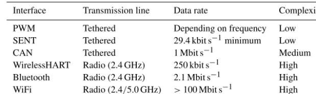
In terms of modern applications like “industry 4.0”, cyber-physical systems (CPS) or embedded control systems sensors and corresponding sensor interfaces are becoming more and more important. For the communication a manifold of inter-faces and bus systems with different properties are used. Ta-ble 1 lists some important sensor interfaces with correspond-ing properties. Besides tethered communication systems also dedicated wireless solutions are available, like Bluetooth, WiFi or WirelessHART.
To use the communication systems in real-time embedded applications like sensor networks for control systems several requirements have to be fulfilled. Reliable and efficient con-trol systems require timely access to the sensor data, both in terms of latency and jitter (Weiner et al., 2014). Latency is the time it takes for data to be transferred from the sender to
the receiver whereas Jitter is the variation of the latency of all the data that are transmitted.
up. Besides the differential signal transmission on twisted pair cables, dedicated CAN transceiver ICs are also needed. But the data rate is significantly higher compared to SENT (ISO 11898, 2015), depending on the length of the cable. For short cables (<40 m) the data rate can be up to 1 Mbit s−1. Currently a wireless physical layer is not specified for these bus systems that are key communication systems for embed-ded systems. As a kind of workaround the wireless transmis-sion is done using standard solutions like WiFi or Bluetooth (Ren et al., 2010). In this case the bus data have to be con-verted into the wireless protocol format before transmission and the receiver converts the data back to the original format. This procedure introduces a large and unpredictable latency and jitter into the data transmission, making real-time appli-cations at least hard to realize or even impossible.
To reduce the amount of cables and connectors and to realize a higher degree of flexibility, wireless communica-tion systems are often used. Standard wireless solucommunica-tions like Bluetooth or WiFi are commonly used for any kind of com-munication and many components are equipped with a wire-less interface. Even though wirewire-less connections are pro-vided by these systems the communication data from embed-ded systems cannot be transferred transparently and in real time due to the complexity and the use of high protocol lay-ers (Yu et al., 2011). Dedicated wireless systems like Wire-lessHART (Hassan et al., 2017) or IO-Link Wireless (Heyn-icke et al., 2018) are specifically developed to support a wide range of usage cases like closed-loop control in real time. Stability, performance, reliability, jitter and latency can meet the requirements for many applications as well. But this kind of wireless system is dedicated to one communication system only, like in case of the WirelessHART for HART communi-cation.
2 PWM, SENT and CAN
The capability of dual-mode radio to act as a one-to-one cable replacement is demonstrated using simple and com-monly used digital communication systems: PWM (pulse-width modulation), SENT and CAN. A PWM interface is some kind of mixture between analog and digital data trans-mission as it is value-discrete and time-continuous. As the information is coded into the pulse width of the signal, the
setup for the unidirectional point-to-point connection is very simple. The transmitter calculates the pulse width corre-sponding to the data, and the receiver just measures the width of the pulse using a timer module for example. Both rising and falling edge are steep and hence suitable for timing mea-surements, e.g. of the latency.
SENT is a digital communication system for the unidirec-tional data transmission from a sensor to a microcontroller (Fig. 1). It enables a simple, robust and cheap point-to-point connection operating on a time base of 3 µs (SENT, 2016). The data are transmitted in nibbles and the value of each nibble is coded into the time between two successive falling edges. Error detection is done by adding a CRC (cycle re-dundancy check) to the transmitted data. As the time for the transmission of a nibble depends on the value of the nib-ble, the data rate is not constant. The minimum data rate for SENT is 29.4 kbit s−1in the worst-case scenario.
CAN is a multi-master bus system commonly used in auto-motive and industrial applications. For the bidirectional data transmission, differential signals are used on a twisted pair cable with a maximum data rate of 1 Mbit s−1(CAN FD runs with 8 Mbit s−1maximum). OSI layers 1 and 2 are defined in the CAN standard ISO 11898 (ISO 11898, 2015). In general the physical layer is realized by a dedicated CAN transceiver whereas the data link layer is part of a microcontroller. Data transfer between the two ICs is done via RX and TX lines (Fig. 1).
3 Dual-mode radio
teth-Figure 1.SENT(a)and CAN schematics(b).
ered communication line of several communication systems by a wireless transmission. Compared to simple on–off key-ing of the carrier, it provides several advantages. In general, the dual-mode architecture is invariant to phase noise of the oscillator, works with high dispersive antennas and uses a mixer instead of a detector (2 times more dynamic).
Additionally, we use the phase modulation variant of the dual-mode architecture with the better robustness of the phase modulation (Heuermann, 2008).
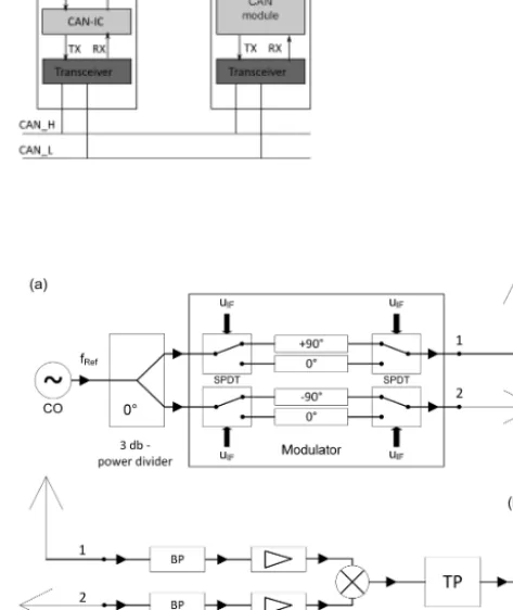
Figure 2 depicts the general setup of a dual-mode radio system including the transmitter and receiver. The setup is very simple and is built up of just a few components. The transmitter consists of an oscillator, a modulator, an ampli-fier and two perpendicular oriented antennas. The frequency of the oscillator can be selected to meet the required fre-quency band, here 4.5 GHz. Other frequencies are possible as well. Due to the coding and decoding of the digital sig-nals the frequency does not have to be very stable, so there are also low requirements on the oscillator. The output sig-nal of the oscillator is split by a 3 dB power divider into two in-phase signals. Within the subsequent modulator each of the two signals is switched by a single-pole double-throw (SPDT) switch to select different paths for the signals. The two different paths include either a 0◦phase shifter or a±90◦ phase shifter. The digital data signal (uIF) controls the SPDT switches to switch between a phase shift of 0◦/+90◦ and 0◦/−90◦respectively. By this switching the phase shift be-tween the two signals after the modulator is 0 or 180◦ repre-senting a digital “0” or “1”. The phase-modulated signals are transmitted by the two perpendicular antennas.
The receiver receives the radio signals, again using two antennas. After an amplification the received signals are con-nected to the input of a mixer to demodulate the signals. The output voltage of the mixer is negative in case of 180◦phase shift of the input signals and positive in case of 0◦phase shift. A low-pass filter filters the mirror frequencies caused by the mixer and a simple electronic converts the resulting signal to the required logic level afterwards.
This method enables a unidirectional wireless commu-nication on a physical layer only, without any protocol or higher layer features. Hence, it can be used for direct cable replacement. For bidirectional communication like the CAN
Figure 2.Schematic of dual-mode radio transmitter (a)and re-ceiver(b).
bus the dual-mode system is just duplicated in the other di-rection. Besides the pure layer-1 functionality, dual-mode ra-dio provides additional advantages compared to other wire-less solutions. As described above it is built of just a few components. The transmitter needs a single oscillator with-out strong requirements with regard to frequency stability or phase noise. The phase shifter and the 3 dB power divider can be realized discrete by using transmission lines, depend-ing on the frequency of the system. The SPDT switches are the critical parts of the discrete system as they mainly deter-mine the maximum data rate. The receiver uses just a mixer and amplifiers if necessary.
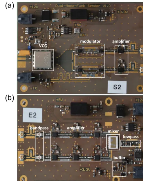
Figure 3.PCB of the transmitter(a)and receiver(b).
4 System architectures and realization
The transmitter and the receiver are realized on dedicated PCBs to enable maximum flexibility for the usage of the sys-tem in prototype syssys-tems (Fig. 3). The transmitter converts a digital input into a dual-mode signal and the receivers con-verts the radio signal back to its digital representation.
The transmitter is designed for an operation with a band-width of 600 MHz (4.2–4.8 GHz) using a VCO (voltage-controlled oscillator). For the 3 dB power divider a Wilkin-son divider is used and the modulator consists of four GaAs switches. These SPDT switches provide a switching fre-quency of about 50 MHz. For the phase shift of±90◦a phase shifter of+90 and−90◦respectively is inserted into the two paths. After the modulator the both signals are amplified to achieve the required output levels. The centre frequency can be chosen as required by the application for next-generation prototypes and systems. The realized system supports a data rate of about 600 Mbit s−1 for the 600 MHz bandwidth, but other bandwidths are also possible, e.g. canals with a band-width of 1–10 MHz.
A band-pass filter of 600 MHz filters the received signals and a three-stage amplifier amplifies the filtered signals af-terwards to compensate for the losses and to enable a trans-mission range of about 3 m. After the mixer the demodulated
signals are filtered by a discrete sixth-order low-pass filter. A subsequent logic IC generates the digital output of 3.3 V representing a logic “1” and 0 V for a logic “0”.
Simple inverted F antennas were used for the prototype.
4.1 PWM
Data transmission using PWM is very simple and hence en-ables a basic test of the dual-mode functionality for wireless sensor data transmission. A single transmitter–receiver pair is used for the unidirectional data transfer (Fig. 4). A pat-tern generator generates the PWM signal that is split into two paths afterwards. One PWM signal is connected to the digital input of the transmitter for the wireless transfer. The digital output of the receiver is connected to an oscilloscope. For comparison the second PWM signal is transmitted via cable (here 2.5 m) and connected to a second input channel of the oscilloscope. This method makes it possible to deter-mine the latency of the wireless link compared to the tethered transmission.
4.2 SENT
The unidirectional SENT protocol provides a slightly higher complexity for the data transmission of sensors compared to the PWM transmission. A Melexis MLX90366 position sensor transmits the measured data via its SENT interface (Fig. 4) (MLX90366, 2015). The SENT data are used as in-put for the transmitter as well as for tethered transmission. After reception of the data via the two transmission paths (dual-mode radio and cable) they are again connected to an oscilloscope. The received data are decoded by the cor-responding function of the oscilloscope. In addition timing measurements are possible as well.
4.3 CAN
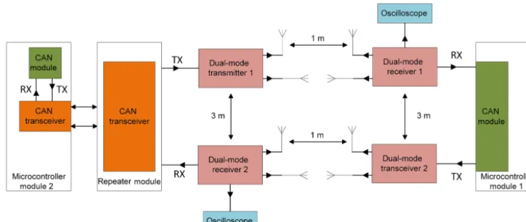
Figure 5.Schematic of the CAN setup using dual-mode radio of the TX and RX lines.
used. To setup a bidirectional communication two dual-mode transmitter–receiver pairs are used, each operating with two separate antennas (Huening et al., 2018). Hence 8 antennas are required for the bidirectional CAN communication. Due to the simple inverted F-antennas used in the prototype, the separation between the sender and receiver was set to 1 m and between the different directions to 3 m for the measure-ments of using the prototype. These settings will be changed in case other antennas are used. As the dual-mode radio acts independently from the antennas they can be easily adapted and optimized to the requirements of the application.
5 Measurements and results
The three different communication systems are used as pro-totypes to demonstrate the features of the dual-mode radio for the wireless transmission of digital bus signals. Besides functional tests this demonstration includes timing and error rate tests as well. As shown for the CAN system, the parallel operation of several dual-mode radio transmission using the prototype needs careful setup of the system to avoid overlap-ping ranges. For future prototypes and system developments, we will work with the frequency multiplex procedure and use additional heterodyne stage for channel selection. Using these improvements will enable the proper operation of sev-eral systems in parallel. The robustness against interferences and multipath propagation is similar to other RF (radio fre-quency) transceiver systems. Using additional noise modu-lators will improve robustness. The dual-mode radio is very robust against fading and the Doppler effect. Depending on output power the transmitter and receiver can be separated similar to other RF transceiver systems.
5.1 PWM
The PWM tests are done using a pattern generator for pulse-width generation and an oscilloscope for analysis of the
re-ceived data. For simplicity a fixed frequency of 5 Hz with a duty cycle of 50 % is used. The data are sent via cable and via the dual-mode system simultaneously to enable a direct com-parison between the tethered and radio link. For both links the received pulse width is still 50 %, and there is no devia-tion from the duty cycle. Timing measurements are done to detect the latency introduced by the radio link including the dual-mode hardware compared to the tethered transmission. Figure 6 depicts the timing behaviour for both the wireless and tethered transmission. The delay introduced by the dual-mode transmission is clearly visible using a rising edge of the PWM signal. Setting the threshold of the rising edge to 50 % of the final high level results in a small delay between tethered and wireless transmission of about 110 ns. Same val-ues are obtained for the falling edge of the signal. Perform-ing several measurements with different PCBs reveal a delay from about 100 to about 300 ns. As this delay is mainly due to the discrete setup of the dual-mode radio we conclude that the delay will be even smaller for a dedicated dual-mode IC.
5.2 SENT
An alternating magnetic field is used for the position sensor to generate different SENT data. The transmission is checked using the SENT decoding option of the oscilloscope. During the duration of the test using the dual-mode radio all SENT data are transmitted correctly, and no single error occurs. The timing measurements are difficult to use for compari-son of wireless and tethered transmissions, as the edges of the tethered signal are rather flat (Fig. 7). Nevertheless it is clearly visible that the wireless data generate a steep rising and falling edge.
5.3 CAN
Figure 6.Comparison of timing behaviour for PWM transmission via dual-mode radio (purple line) and via cable (blue line).
Figure 7.Comparison of timing behaviour for SENT transmission via dual-mode radio (blue line) and via cable (purple line).
wireless link the system can also use standard tethered RX and TX connections. For the CAN nodes it does not make any difference whether the tethered or the wireless link is
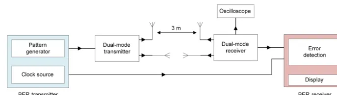
Figure 8.Setup for wireless CAN bit error measurement and measurement of the eye diagram.
Figure 9.Eye diagram at a frequency of 1 Mbit s−1.
The measurement of the bit error rate (BER) and of the eye diagram is done using a similar setup to that depicted in Fig. 8. The data signal of the BER transmitter is connected to the dual-mode transmitter and the clock signal of the BER transmitter is connected to the clock input of the BER re-ceiver using a coaxial cable. The output of the dual-mode receiver is connected to the data input of the BER receiver. The eye diagram is measured using an oscilloscope.
Both the measurement of the bit error rate and of the eye diagram is done at 1 Mbit s−1, the maximum data rate of high-speed CAN. During a measurement time of 30 min no single transmission error occurred. From statistics this result yields a bit error rate of 10−9. The corresponding eye dia-gram is depicted in Fig. 9. The eye is widely open and con-firms the excellent signal properties as well as the stability of the dual-mode system and a low jitter.
6 Discussion
The prototype for the dual-mode radio used in this study is designed in such a way as to combine simple usage and high flexibility. The transmitter and receiver just have a single dig-ital input and output pin, respectively, on the digdig-ital part, with the two antenna outputs on the other side. In addition
the dual-mode system operates on the physical layer only and converts digital data to the radio representation and vice versa. The functionality of the dual-mode radio system is demonstrated using three different communication systems: PWM, SENT and CAN. For all three communication sys-tems the data transfer runs stably and reliably without any errors and it is fully transparent for the bus nodes. Therefore the system can be used for any kind of wireless data transfer of digital data without any restrictions due to the protocol. As the system is independent of the antennas used for trans-mission, suitable antennas can be chosen depending on the requirements of the application.
sign of the dual-mode radio system, e.g. during the design of a dual-mode radio IC. Higher bandwidth and data rates can also be realized.
Besides the functional proof of the wireless data transfer using dual-mode radio, timing and stability measurements were done. The timing measurements running the PWM data transfer result in a latency of the wireless data transfer of less then 300 ns. A detailed analysis of the discrete setup reveals that this latency is mainly introduced by the SDPT switches. Based on this analysis we conclude that the latency will be significantly smaller when dedicated ICs are used. Detailed jitter measurements were not yet done. But the shape of the eye diagram clearly shows an open eye at a data rate of 1 Mbit s−1, with rather small variation of the slopes. Hence the jitter is low, but a detailed jitter analysis has to be done, in particular to separate the jitter introduced in the dual-mode radio from the jitter by the bus system itself.
Based on the presented results and properties of dual-mode radio, the new wireless link clearly demonstrates its capabil-ities for a real-time wireless data transfer for embedded bus systems. This system is hence the only known technology for a fully transparent wireless data transmission on the physical layer. The currently introduced latency can be significantly reduced when using a corresponding IC.
7 Summary and conclusion
In this paper the use of dual-mode radio for wireless sen-sor interfaces is presented and analysed with regard to exam-ple applications, real-time capability and reliability. A dis-crete prototype for the wireless link is used to realize three different sample applications for PWM, SENT and CAN in-terfaces. For all three interfaces the wireless data transfer is possible without any restriction. Timing measurements are done using the PWM interface, resulting in a latency of about 300 ns maximum, caused by the discrete prototype. The measurements of the bit error rate and the eye diagram reveal a stable and reliable data transmission using CAN up to 1 Mbit s−1 with low jitter. These results lead to the con-clusion that dual-mode radio offers the chance for real-time wireless data transfer for many different embedded bus sys-tems. A transfer of the dual-mode system to an IC will further reduce the latency and hence will enable real-time wireless data transfer for digital sensor interfaces with very low la-tency and jitter.
Competing interests. The authors declare that they have no con-flict of interest.
Acknowledgements. The research was funded by the Depart-ment of Electrical Engineering and Information Technology at the University of Applied Science Aachen.
Edited by: Rosario Morello
Reviewed by: two anonymous referees
References
Hassan, S. M., Ibrahim, R., Bingi, K., Chung, T. D., and Saad, N.: Application of Wireless Technology for Control: A Wire-lessHART Perspective, Procedia Comput. Sci., 105, 240–247, 2017.
Heuermann, H.: Hochfrequenztechnik, Komponenten für High-Speed- und Hochfrequenzschaltungen, Vieweg+Teubner, Wies-baden, 2005.
Heuermann, H.: Dual Mode Radio: A new Transceiver Architec-ture for UWB- and 60 GHz-Applications, European Microwave Conf., Amsterdam, 27–28 October 2008.
Heynicke, R., Krush, D., Cammin, C., Scholl, G., Kaercher, B., Ritter, J., Gaggero, P., and Rentschler, M.: IO-Link Wireless enhanced factory automation communication for In-dustry 4.0 applications, J. Sens. Sens. Syst., 7, 131–142, https://doi.org/10.5194/jsss-7-131-2018, 2018.
Huening, F., Heuermann, H., and Wache, F.-J.: Wireless CAN, Tagungsband AALE 2018, VDE Verlag, Berlin, 2018.
ISO 11898: Road vehicles – Controller Area Network (CAN), available at: https://www.iso.org/standard/67244.html (last ac-cess: 3 July 2018), 2015.
MLX90366 data sheet: Rev 1.2, Melexis, 2015.
Ren, Y., Fu, C., Wang, T., and Jia, S.: CAN Bus Network Design based on Bluetooth Technology, 2010 International Conference on Electrical and Control Engineering, Wuhan, China, 25–27 June 2010.
SENT: Single Edge Nibble Transmission for Automotive Applica-tions, SAE J2716 https://www.sae.org/standards/content/j2716_ 201604/ (last access: 3 July 2018), 2016.