COMPARISONIN CCGT POWER CYLCE USING
NAPTHA AND NATURAL GASUSING MAT LAB
CODING
Neelam Khandelwal
1, Binit Kumar Jha
2, Nishtha Chaudhary3,
PrateekSingh
4, Raghuvendra Singh Som
51
Assistant Professor,
2Professor & Head,
3,4,5Students, Department of Manufacturing Technology,
JSSATE, Noida (India)
ABSTRACT
A combined cycle is a synergistic combination of two or more power cycles operating at different temperatures
running independently. Normally the cycles are classified as a 'topping' and a 'bottoming' cycle. Presently, the
gas steam combined cycle is widely accepted, where Brayton Cycle has high source temperature and rejects
heat at suitable temperature that is conveniently used as the energy source for the Rankine Cycle. The
performance of combined cycle depends upon number of parameters like TIT, component efficiencies, turbine
exhaust temperature, degree of supplementary firing and condition of steam generation. Our work is to find
specific work output and optimize the thermal efficiency of combined cycle by reheating without supplementary
firing and using two different fuels isnapthaand natural gas when steam is generated at 12 bar 3250C for a given set of parameters like temperature, pressure ratio and A/f ratio. MAT lab coding has been used for
validation of research work.
Keywords: Combined Cycle, Optimization, Steam turbine, Gas turbine, Efficiency,
Supplementary heating, , A/F ratio, Pressure ratio, comparison between fuels(Naptha and
Natural Gas)
I. INTRODUCTION
The introduction of combined cycle has opened new avenues in the field of power generation. The gas turbines that
were initially used in peak load power generation and emergency conditions could be used in base load power
generation. Combined Cycle is a synergistic combination of gas cycle and power cycle. Thus performance of
combined cycle depends upon the performance of gas cycle and steam cycle. So in order to achieve this objective the
parameters that affect the performance of gas turbine (maximum temperature, component efficiency, a/f ratio and
pressure ratio) the limitations that restrict the performance of gas turbine (space, cost and metallurgical limitations)
were determined .
Flour corporation researched on the process of obtaining energy during regasification of LNG in CCGT. This
that efficiency could rise for low turbine pressure ratio and for small regeneration degreeand regeneration degree
causes an increase in efficiency when it is small enough .Considerable work on comparative evaluation of advanced
combined cycle alternatives is reported in literature .IG RICE has discussed the effect of pressure ratio and firing
temperature on power output, thermal efficiency, turbine exit temperature. According to this reheat cycle gas turbine
efficiency is degraded slightly over the simple cycle for equal firing temperature and the reheat cycle gas turbine
output is increased significantly. It has also been mentioned that as the pressure ratio is increased the compressor
discharge temperature also increases. However gas generator exit temperature decreases with increase in pressure
ratio. He emphasize on the role of pressure ratio on specific power output and thermal efficiency. And find that as the
pressure ratio for compression increases the specific work output for gas turbine increases whereas work output in
steam turbine is decrease .M.A. Da Cunha et. Al. has discussed the concept of inter cooling and reheat for gas
turbines and the effect of position of inter-cooling and reheating on gas turbine performance. In our analysis we
discuss the optimized efficiency of the combined cycle with given sets of constraints and variables. The optimized
result will give the maximum efficiency of the Combined Cycle which defines the running conditions of both the Gas
Turbine and Steam Turbine Cycles. In 2012 Thamir K. Ibrahim has discussed the effect of compression ratio on
performance of Combined Cycle Gas Turbine. R-I Crane has discussed the critical analysis of the thermodynamic
advantages of reheat in Gas Turbines.
In the present analysis, the specific work output and thermal efficiency of combined cycle is determined at different
a/f ratio in the range of 50-130 and pressure ratio in the range of 4-40for the two fuel naptha and natural gas. It is
observed that specific work output and thermal efficiency is high for natural gas as compared as naptha.
II. THERMODYNAMIC MODELING OF COMBINED CYCLE
In the present analysis of combined cycle, the effect of various parameters like a/f ratio), pressure ratio on
specific work output and thermal efficiency. The effect of reheat, supplementary heating and condition of steam
generation i.e. pressure and temperature on specific work output and thermal efficiency are also analyzed.
To analyze the present study the methodology adopted are Firstly calculate worknetl, work net2 and efficiency
1, efficiency 2 at different a/f ratio and pressure ratio for Reheat , inter-cooling without supplementary firing for
natural gas and naptha when the steam is generated at 12 bar and 325o
Once the exhaust gas has temperature needed for steam generation steam cycle would contribute.
Thus we can calculate work 3 and efficiency 3.
Here,
Fig.1 Gas turbine cycle (Brayton cycle) Fig.2 Rankine cycle without
without supplementary heating with reheat supplementary heating with reheat
and with intercooling and with intercooling
III. ANALYSIS OF GAS TURBINE CYCLE
3.1 With Reheat without Supplementary Heating
t i pi γ-1/ γ
--- = ---
t 1 p1
where γ –1
--- = 0.2857
γ
Also, pi = sqrt (p1 x p2), where Sqrt = Square Root
Now,
ti - t1
--- = ηc
tia = ---+ t1 ηc
Now, similarly
t2 – tx
t2a = --- + tx
Ηc
Here, for perfect inter-cooling, tx = t1
t2 – t1
So t2a =
---
+ t1 ηcNow, to calculate t3
mf x L.C.V = (mf + ma ) x Cpg x (t3 – t2a)
ma = 1 x a/f
mf x L.C.V
t3 =
---
+ t2a(mf + ma) x Cpg
t3 p3 0.2857
--- = ---
t4 p4
and p4 = sqrt (p3 x p5)
t3
t4 =
---(p3 / p5) 0.2857
and t5 = t3
t5
t6 = ---
t5– t6a
ηt = - --- , t6a = t5 – ηt (t5 – t6) t5
– t
6Here,
wt = (mf + ma) x Cpg x (t3 - t4a + t5 –t6a)
and
wc = ma x Cpa x (t2a – tx + tia – t1)
Now,
Work 1
Thermal = ---
Efficiency mfx L.C.V + (mf + ma) x Cpg x (t5 – t4a)
IV ANALYSIS OF STEAM CYCLE
4.1 With Reheat without Supplementary Heating
Mass of steam generated by utilization of waste energy.Work (steam) = ms x (h3-h2)
Now to calculate 'ms'
(mf+ ma) xCpgx (t8– t9)
ms =
---(h3 - h2)
Also,
work net 2 = (work 2)
---
(mf + ma)
Efficiency 2 = (work 2)
---
V. ANALYSIS THROUGH MATLAB CODING
5.1 Analysis of Combined Cycle With Reheat Without Supplementary Heating when steam is
generated at 12 bar 325
0C for naptha
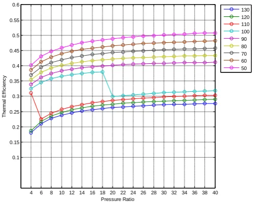
4 6 8 10 12 14 16 18 20 22 24 26 28 30 32 34 36 38 40 0.1 0.15 0.2 0.25 0.3 0.35 0.4 0.45 0.5 0.55 0.6 Pressure Ratio T h e rm a l E ff ic ie n c y 130 120 110 100 90 80 70 60 50
Fig. 1 : Thermal Efficiency v/s Pressure Ratio at Different A/f Ratio with Reheat Without
Supplementary Heating when Steam is Generated at 12 bar 325
0C
The Optimized Value of Efficiency at Air/Fuel Ratio 50.00 and Pressure Ratio 40.00 is 0.508.
1) Steam cycle become effective for A/F ratio 110 and lower.
2) At A/F ratio of 100 Efficiency 3 increases from pressure ratio 4 to pressure ratio 18. Efficiency 3 decreases
sharplyin the range of 18 to 20 bars. From 20 bar onward Efficiency 3 continuously increase with pressure.
3) At a particular pressure ratio the Efficiency 3 increases with lowering of A/F ratio. 4) The optimized value
of Efficiency 3 is at A/F ratio 50 and pressure ratio 40.
5.2 Analysis of Combined Cycle with Reheating without Supplementary Heating When Steam is
Generated at 12 Bar and 325
0Cfor Natural Gas
Thermal Eficciency v/s pressure ratio at different A/f ratio with reheat without supplemantary
heating when steam is generated at 12 bar 3250C
The optimized value of efficiency value of efficiency at A/f ratio 120 Pressure ratio 40 is 0.517.
1) Steam cycle become effective for A/f ratio 110 and lower.
2) At A/f ratio of 100 efficiency 3 increases from pressure ratio 4to prssure ratio 18. Eficiency 3 decreases
sharply in the range of 18 to 20 bar onwards efficiency 3 continuously increases with temprature.
3) At a particular pressure ratio the efficiency 3 increases with lowering of A/f ratio.
4) The optimized value of efficiency 3 is ar A/f ratio 50 and pessure ratio 40.
5) The efficiency of steam cycle increases with the increament of L.C.V. of fuel.
VI. CONCLUSION
Turbine exit temperature is decreasing as pressure ratio is increased keeping A/F ratio constant because turbine
maximum temperature does increase with pressure ratio but this effect is marginalized by the increase of
expansion ratio owing to higher pressure ratio. At a particular pressure ratio if a higher A/F ratio is optimized
then turbine maximum temperature goes on decreasing as the mass of fuel is constant and at higher A/F ratio the
heat released due tomass of fuel is used for raising the temperature of higher quantity of flue gas resulting in low
temperature of turbine inlet temperature. In the gas turbine cycle the efficiency first increase and then decreases
with increasing pressure ratio when steam is generated at, 12 bar 3250C with reheat .A steam cycle does not effective at higher A/F ratio. Generally steam cycle is effective at A/F ratio 110 and less than it. Efficiency of
steam cycle is decreases as pressure ratio increases when steam is generated at 12 bar 3250C, with reheating and without supplementary heating. In combined cycle for A/F 130 to A/F 100 the turbine exit temperature is less
than 3250 C i.e. ( the condition of Steam generated )so steam cycle does not contribute and, Efficiency = Efficiency 1.
Steam cycle became effective at A/F ratio of 100 and lower. Here
Efficiency = Efficiency 1 + Efficiency 2.
At a particular pressure ratio the efficiency of combined cycle (using naptha is 0.508 and natural gas 0.517)
increases at lower A/F fuel ratio. Thus by comparing the fuels we obtained natural gas has higher efficiency in
same conditions when compared to naptha and it is seen that with using the more higher L.C.V. fuel efficiency
of steam cycle increases.
VII. NOMENCLATURE
mfMass of fuel
maMass of Air
a/f Air Fuel Ratio
ηc Isentropic compressor efficiency
hf3 Enthalpy of feed water after considering pump work.
Work 1 Work output in gas turbine per kg of fuel burnt. Work net 1 Work output in gas turbine cycle per kg of flue gas.
ms Mass of steam
Work 2 Work output (steam cycle.) per kg of fuel burnt Work net 2 Work output (steam cycle.) per kg of flue gas Efficiency 1 Thermal efficiency for gas turbine cycle
T.I.T Turbine Inlet Temperature
w/o Without
H.R.S.G Heat Recovery Steam Generator
H.P.C High Pressure Compressor
L.P.C Low Pressure Compressor
H.P.T High Pressure Turbine
L.P.T Low Pressure Turbine
ti Actual temperature of air after passing low pressure
Compressor
t2a Actual temperature of air after passing high pressure Compressor
t4a Actual temperature of flue gas after passing high pressure Turbine
t6a Actual temperature of flue gas after passing low pressure Turbine tx Temperature of air after passing through intercooler.
wt Work output of turbine.
wc Work required in the compressor.
Tia Actual temperature after compression
L.C.V Lower Calorific Value.
p1 Ambient pressure.
t1 Ambient temperature.
Cpg Specific heat of flue gas.
Cpa Specific heat of air.
Z The percentage of fuel that is burnt in Combustion Chamber
Efficiency 2 Thermal efficiency for steam cycle Work 3 Specific work output for combined cycle Efficiency3 Thermal efficiency for combined cycle
p2 Compressor exit pressure.
t2 Compressor exit temperature.
t3 Turbine Inlet Temperature
t4 Isentropic Turbine Exit Temperature (w/o Reheating)
t5 Temperature after Reheated.
t6 Isentropic Turbine exit temperature (with Reheating).
p3 Pressure in combustion chamber for gas turbine cycle.
p4 Reheat Pressure.
ti Isentropic Temperature of air after intercooler.
pi Intercooler Pressure.
REFERENCES
[1] Flour corporation researched in September 1979 improving the quality of natural gas to improve the
efficiency of ccgt.
[2] Louis JF Hirao Ka K and E.I. Masri M.A. "Comparative study of the influence of different means of
turbine cooling on gas turbine performance" ASME paper 83 - GT 180.
[3] G.CARRY and A.COLAGE July "Steam cycle regeneration influence on Combined Gas-Steam power
plant performance" ASME paper, 1985
[4] Bolland April, “A Comparative Evaluation of Advanced Combined Cycle Alternatives”. Journal of
Engineering for Gas Turbine and Power, Vol.113 Pages 190-202, 1991
[5] I.G Rice January "The Combined Reheat Gas Turbine & Steam Turbine Cycle" Journal for Engineering
for power vol. 102, PP 35-41, 1980
[6] M.A Da Cunha Alves H F De Franca Mendes Carneiro, J R Barbosa, l.E.Travieso, P pilidis and K W
Ramsden, “An insight on inter-cooling and reheat Gas Turbine”. Proc Institute of Mechanical Engineers
Vol. 215 Part A, 2001
[7] Thamir .K.Ibrahim “Thermodynamic analysis of gas turbine power plant” internal journal of physical
science vol 6 (14), 2011
[8] R-I Crane,1998 "A Critical Analysis of the Thermodynamic Advantages of Reheat in Gas Turbines." Proc
Institute Mech. Engineers Vol 212 Part A.
[11] R.Yadav, Steam and Gas Turbines( Central Publishing House, Allahabad).
Biographical Notes
Ms. NeelamKhandelwalis working as a Assistant Professor inManufacturing TechnologyDepartment
,JSSATE, Noida,India.
Prof. Binit Kumar Jha is working as a Professor & Head inManufacturing TechnologyDepartment, JSSATE,
Noida,
India.
NishthaChaudharyis student in Department of Manufacturing Technology, JSSATE, Noida,
Prateek Singh is student in Department of Manufacturing Technology, JSSATE, Noida,