Numerical Model Related to Impact Fluid / Solid Under the
action of an Electric Field
Hocine Alla1, Somia Freifer1
1Université des Sciences et de la Technologie d’Oran (USTO), Faculté des Sciences, BP 1505 El
M’Naour Bir el Djir Oran, 31000, Algérie
Abstract. The electrowetting is an area of significant interest. Many experimental studies have been conducted to find the relationship that binds the physical parameters of said phenomenon: the percentage of the white area inside the pixels of different sizes depending on the applied voltage etc. Our study is to develop a CFD model to validate the experimental results for the behavior of fluids (oil colored) within the reflector screens under the action of electric field.
1 Introduction
Electrowetting has become one of the most widely used for manipulating small amounts of liquids on surfaces under the influence of an electric field. This phenomenon is used in many industrial processes such as microfluidic "lab-on-a-chip", the devices (plans) of adjustable lenses to modify the convergence so in the industry of display screens. Our study is to develop a CFD (Computational Fluid Dynamics) method based on the VOF (Volume of Fluid) to follow the behavior of the liquid (in our case we choose the oil) inside a pixel under action of an electric field.
2 Mathematical Model
When a drop is placed on top of an electrode and the latter is then charged, the contact angle between the liquid surface (the drop) and the solid surface (electrode) is reduced. This is called electrowetting. Lippmann equation[1] reflects the change in the interfacial tension between the solid SL and the liquid as a function of the voltage V of the drop by the equation (1):
σSL V σSL V 0 CV (1)
Where, C is the specific capacity of the dielectric layer. From Young's equation (2) which describes the relationship between the contact angle and the interfacial tension SL between the interface solid-gas, solid-liquid and liquid-gas in the line of contact at the triple point (see Figure 1)
/
C
Owned by the authors, published by EDP Sciences, 2013
/
This is an Open Access article distributed under the terms of the Creative Commons Attribution License 2.0, which permits unrestricted use, distribution, and reproduction in any medium, provided the original work is properly cited.
cosθ SG SL
LG (2)
Equation (3) Young-Lippmann [1] is given by:
cosθ V cosθ
LG V (3)
0: is the contact angle at equilibrium (V=0).
0: The permittivity of vacuum (8.85 x 10⁻¹² F/m).
: The dielectric constant of the dielectric layer.
t: The thickness of the dielectric layer.
3 Numerical Model
A fundamental method to solve two-phase flow is the volume of fluid method (VOF), which was developed by Hirt and Nichols (1981). VOF method is a fixed mesh with the interface between immiscible fluids is modeled by a characteristic function (called volume fraction) [2].
3.1 The model equations
The Equations of mass and momentum conservation (4) and (5) for each phase are given by [3]:
.V= 0 (4)
V . VV P μ V g FSF (5)
Where V is the velocity vector, P is the pressure, and the FSF is the surface force vector, μ is the viscosity and density . The mixture density is calculated as follows:
ρ α ρ (6)
Where αk is the volume fraction of the liquid. Any other property of the mixture is calculated as follows:
φ
(7)
Where:
αk =0 : The cell is empty.
αk =1 : The cell is full.
0<αk<1 : The cell contains an interface between the fluids.
The surface tension has been modeled as a regular variation of the capillary pressures through the interface.
FSF αkn / (9)
n α (10)
k . n | | | |. |n| . n (11)
Where n is the surface normal, n is the unit normal of the curvature. The surface normal n was evaluated in cells containing the interface and requires knowledge of the amount of volume of fluid present in the cell.
To calculate the electric potential in every area, the second order discretized form of the Laplace equation is solved at the beginning of each time step iteration [4].
. ψ x, y, z 0 (12)
3.2 Geometry and boundary conditions
We chose to study the problem in two dimensions. For this, the geometry is a square of dimension 1x1m2. We used a structured grid square of size 5 x 10⁻⁴ using the preprocessor Gambit 2.2.30.For
the boundary conditions we used two conditions: the input condition is defined as a pressure inlet and the side walls are declared type Wall. Where the electrode is fixed between the insulator (Teflon) and the substrate is a white rectangle 15nm thick. The liquids used in this study are dodecane and water. A drop of dodecane whose radius is 10 m is defined in the solver Ansys Fluent 12.0.16. The voltage applied to the surface of the Teflon is 15 volts. (See Figure 2.).
Fig. 3 - The behavior of oil in water. a) no electric field b) with the electric field. [5]
3.3 Results and Discussion
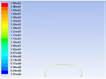
VOF method available in the code Ansys Fluent calculation allowed us a better observation of the drop profile and from the equation of fluid dynamics. The movement of the drop is observed when a voltage of 15V is applied to the electrode of time ranging from t = 0 to t = 2.16 e-2s (FIG. 4).
Fig. 5 - changing the radius of a drop of oil in water of dodecane under the effect of an electric field. We note that although the radius decreases as time increases.
Fig. 6 - electric potential distribution.
Figure 6 shows the distribution of equipotential for an actuation voltage of 15V. The maximum value of the electric potential is about 15V near the electrode.
a) b)
-4 -2 0 2 4
20 22 24 26 28 30 sur fa ce t ens io n ( m N /m ) Electric Field(v) Numerical model Theoretical model
-2 0 2
c)
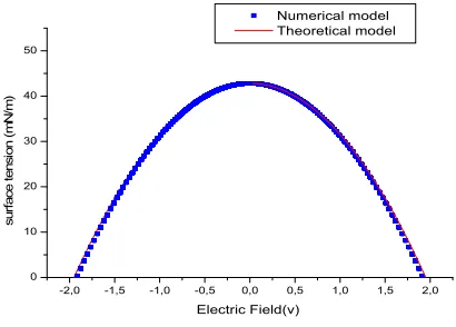
Fig. 7 - Solid-liquid surface tension as a function of electric field . a) dodecane, b) tetradecane, c) decane.
The VOF model reflects the behavior of a drop of oil in the water under the effect of an electric field. We thus find the profile of the Lippmann equation (1) in perfect agreement with our model. This encourages us to find other relationships related to the behavior of droplets under the influence of an electric field, such as the numerical validation of the equation of Young-Lipmann.
References
1. B. Berge,Electrocapillarité et mouillage de films isolants par l'eau, CRAS 317 Série II, 1993, 157 2. Alla H., Freifer S., Medjellel C., Contribution au phenomène de mouillabilité en présence d’un tensioactif anionique «SDS» et non ionique «C11E5», 19ème Congrès Français de Mécanique, Marseille, 2009.
3. Prashant R. G., Vivek V. R., Raghunath V. C., Dynamics of Drop Impact on Solid Surface: Experiments and VOF Simulations, Wiley InterScience, January 2005.
4. Mohseni K., Arzpeyma A., Dolatabadi A.,Behaviour of a Moving Droplet under Electrowetting Actuation: Numerical Simulation, The Canadian Journal of Chemical Engineering,Volume 84, Issue 1, February 2006.
5. Thibault.R.C.,Hayes.R.A.,Feenstra.B.J.,Schlangen.J.M., Liquid behavior inside a reflective display based on electrowetting,Journal of applied physics ,volume 95, number 8 ,2004.
-2,0 -1,5 -1,0 -0,5 0,0 0,5 1,0 1,5 2,0
0 10 20 30 40 50
sur
fa
ce t
ensi
on (
m
N
/m
)
Electric Field(v)
![Fig. 2 - a) Experimental Model [5] b) geometry in gambit.](https://thumb-us.123doks.com/thumbv2/123dok_us/8990848.1437146/3.482.41.435.408.541/fig-experimental-model-b-geometry-gambit.webp)