Design And Fabrication Of An Incense Stick
Making Machine
Madhur Bakhle, Shivani Gite, Ameya Poyarekar, Ayaz Siddiqui, Shradha Patil
Abstract: The design and fabrication of a low cost pedal operated incense-stick making machine to alleviate the labor intensive work associated with the production of bamboo-cored incense sticks is outlined in this paper. The machine is based on the mechanism of extruding the incense stick paste over the bamboo stick. The main components of this machine include a foot-pedal, a compound gear-train system, rack and pinion system and an extruder. As the paste used is of a semi-solid nature and a high force was needed for extrusion, a confined compression test using Universal Testing Machine was carried out to obtain rough estimates of the force required for the extrusion. During this experiment a known force was applied, varied and exerted on the rack until the paste was extruded out of the die. Using this force estimate, FEA analysis and theoretical calculations, a suitable two-stage compound gear-train system and a foot-pedal was designed. The lever and gear-train system was designed ergonomically so that the applied force results in a minimal muscle fatigue for the operator.
Keywords: incense stick making machine; gear train; rack and pinion; piston; cylinder; foot-pedal; ratchet and pawl; extruder; die; nozzle; paste ————————————————————
1.
I
NTRODUCTIONIncense sticks called agarbattis in India, are becoming internationally known as a ritual product used for spiritual purpose producing fragrance for aromatherapy and meditation. The agarbatti workers in rural areas lack efficient tools and education to develop better means of processing agarbattis. The current manual mixing processes are physically exhausting and time consuming. The incense sticks industry employs around half a million poor women. Thus, there is a need for design and fabrication of a manually operated machine for productions of quality incense stick. A machine that does not require any external power supply and has simple operation compact and affordable is to be designed for good production rates. Incense sticks industry is a 1800 crore industry India [1]. Every year more than 1000 billion sticks are produced and the market is growing at a rate of 7% per year. India exports close to Rs. 350 crore worth of incense sticks every year. There are about 5,000 incense companies in India which take raw un-perfumed sticks hand-rolled by approximately 200,000 women working part-time at home, apply their own brand of perfume, and package the sticks for sale. An experienced home-worker can produce 4,000 raw sticks a day. There are about 25 main companies, who together account for up to 30% of the market, and around 500 of the companies, including a significant number of the main companies, are based in Bangalore [2]. The cost of an automatic incense-stick machine, pedal-driven machine, motor-driven semi-automatic machine, starts from INR 80000, INR 20000 and INR 32000 respectively.
2.
M
OTIVATIONThe workers in the agarbatti industry face severe health hazards ranging from bruising of palm-skin to back-pain problems and are paid a pittance for such arduous work. A machine that will reduce the labour of incense-stick making is needed, as about 0.5 million women workers in India are involved in the industry [3]. Development of such a machine will not only aid these workers in making incense-sticks but will also provide livelihood opportunities for other poor women workers who are either unemployed or are involved in challenging and labour-intensive non-cottage industries. With such a machine they will be able to make more sticks in the same given time, eventually earning more money.
3.
AIM AND OBJECTIVESThe aim of the project is to design a manually operated agarbatti making machine for micro enterprises in India focusing functionality, ergonomics and safety.
Objectives of the project are:
1. To collect data of existing designs through product study, visual design exploration, user study and market study.
2. To develop a simple mechanism to convert the manual input into force required to carry out the extrusion process for making the incense stick.
3. To design components of right sizes and material to make the machine strong and reliable at an affordable cost.
4. To design to make the machine compact and to attain a satisfactory rate of production.
5. To fabricate the machine and inspect it.
4.
SCOPEScope of the project is confined to design and fabrication of an incense stick machine for the incense stick of diameter of 3 mm and 6-7 inches in length. The powder used in _______________________________
Madhur Bakhle, Shivani Gite, Ameya Poyarekar,
Ayaz Siddiqui, Shradha Patil
B.E, Assistant Professor, Department of Mechanical
Engineering
Fr. C. Rodrigues Institute of Technology, Vashi, Navi
Mumbai 400703, India
116 production rate of the machine will be 30 incense sticks per
minute. The project includes design, fabrication and inspection of machine to produce quality incense stick.
5.
DESIGN AND DEVELOPMENT5.1 Market Survey
The currently available incense stick making machines in the Indian market are of manual, automatic and semi-automatic. Comparison of the three types of machine is shown in table 5.1.
Table 5.1 Comparison of machines
5.2 Mechanism
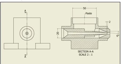
The foot pedal actuates the ratchet and pinion which is on the same shaft of the first gear of the gear train. The second gear is co-axial with the pinion of the rack and pinion arrangement which drives the piston. The rack pressurizes the incense paste which is fed into the cylinder and pushes the paste into extrusion housing. The block diagram of the mechanism is shown in figure 5.1.
Figure 5.1 Mechanism
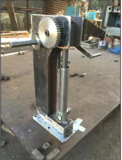
5.3 Prototype model and components
The prototype model is designed to transmit the force applied on the foot pedal to the piston in the cylinder which contains the agarbatti paste. This compressive force then causes the extrusion of the agarbatti stick. The prototype model has been shown in fig.5.2. The major components of the prototype model are:
1. Die kit
2. Extrusion housing 3. Cylinder and piston 4. Rack and pinion 5. Gear trains 6. Body 7. Foot pedal
Figure 5.2 Prototype model
5.4 Design Specifications
The following is the list of various parameters of the components that were designed:
Extrusion force:
Theoretical force calculated 5700.4 N Practically observed force 6000 N Transmission mechanism:
Table 5.2 Design summary tables
Length (mm)
Diameter (mm)
Module (mm)
No. of teeth
Thickness (mm)
Rack 450 30 3 58 -
Pinion - 40 3 14 50
Gear 1 - 81 3 27 20
Gear 2 - 135 3 45 20
The gear train was tested for dynamic and wear failure and found to be safe.
Figure 5.3 Extrusion kit dimension specifications
Feature Manual Semi-automatic
Fully automatic
Electricity
supply Not required Required Required Human effort More Less Negligible
Electronic
components None Less More
Cost (in Rs.) 13,500 45,000 85,000 Production rate
(no. of
sticks/min)
Figure 5.4 Transmission mechanism dimension specification
6.
F
ABRICATION AND TESTING6.1 Fabrication Details
The fabrication of each component was done based on the design. The following table shows the list of operation performed for the fabrication of each components and its weight.
Table 6.1 Fabrication Table
Part Operations performed Weight (kg) Base Plate
Gas cutting Grinding Drilling
2.2
Machine Body
Gas cutting Grinding Drilling Welding
(3.5*2) + 0.5 +0.2
= 7.7
Extrusion Housing
Milling Threading Drilling Tapping
1.6
Rack and Pinion Housing
Milling
Tapping 5.4
Gear 1 Gear milling
Keyway milling 0.6 Gear 2 Gear milling
Keyway milling 1.9 Gear shaft
Turning Facing Keyway milling
1.4
Bearing covers
Gas cutting Grinding Drilling
0.5 * 2 = 1
The fabricated model of the machine has been shown in the following figures. The die assembly, piston-cylinder, rack and pinion, gear train, ratchet and pawl the piston retracting handle and the machine frame can be seen in the following figures.
Fig. 6.2 Side view of prototype
Fig.6.3 Front view of prototype
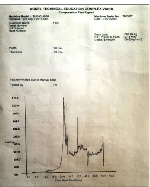
6.2 Testing on UTM Machine
118 process. The load at which the extrusion began was found
to be 6000 N; this has seen in the following graph (fig. 6.3). Thus is it seen that the theoretical and experimental value are almost equal and approximately equal to 6000N.
Fig. 6.2 UTM setup
Fig. 6.3 UTM Test Graph
7.
COST ANALYSISThe total cost incurred for the project is shown below in the Table 7.1. The cost includes procurements of individual components as well as their fabrication cost.
Table 7.1 Cost Table
Component Cost (Rs.)
Extrusion housing 1500
Die 1000
Side plates 900
Gears 1200
Cylinder 400
Rack and pinion 750
Bearings 520
Shaft 500
Powder and sticks 350 Miscellaneous 110 Total Cost 7230
8.
R
ESULTThe fabricated machine was found to work as expected with a production rate of 30 incense sticks per minute. Each refill of paste in the cylinder was observed to give up to 190 incense sticks, which is close to the theoretical value of 200.
9.
C
ONCLUSIONIt has been demonstrated that the mechanism developed makes good quality incense-sticks. The incense stick machine is cheaper than existing machines in the market, and the foot-pedal causes less fatigue so is easier to operate. The quality of incense-sticks, various cross-sectional shapes and length that can be produced by the machine cannot be otherwise achieved manually. It is felt that this incense stick machine can succeed as a viable product in India.
ACKNOWLEDGEMENTS
We thank our project guide Mrs. Shradha Patil for her valuable guidance and insight. It has helped us a long way in taking key decisions and troubleshooting problems which occurred in the project. We also thank the college authorities of Fr. C. R. I. T. Vashi for permitting us to use the equipment and facilities available for conducting various essential activities of our project.
R
EFERENCES[2] Experimental determination of an optimal foot pedal design - by Donald J. Trombley, B.S, in E.E, a thesis in industrial engineering. Year: 1966.
[3] https://en.wikipedia.org/wiki/Incense_of_India, last accessed: 11/9/2015.
[4] http://www.thehindubusinessline.com/economy/indi
an-agarbatti-time-formakeover/article2604235.ece, last accessed: 11/9/2015.