Real-time Implementation of Foreground Object
Detection From a Moving Camera Using the ViBE
Algorithm
Tomasz Kryjak, Mateusz Komorkiewicz, and Marek Gorgon
AGH University of Science and Technology, Krakow, Poland
{kryjak, komorkie, mago}@agh.edu.pl
Abstract. The article presents a real-time hardware implementation of a foreground object detection for a non-static camera setup. The system consists of two parts: the calculation of the displacement between two consecutive frames using a correlation based corner tracker and background generation method ViBE (Visual Background Extractor). The paper discusses details of the used hardware modules, resource uti-lization, computing performance and power dissipation. The solution was evaluated on sequences recorded with a static and moving camera. The system was success-fully tested on a hardware platform with an FPGA device. It allows to process a 720
×576 pixels and 50 frames per second video stream in real-time.
Keywords:foreground detection, background generation, background modelling, ViBE, FPGA, real-time system, image processing, moving camera, background compensation
1.
Introduction
Detection of foreground objects is one of the most important issues in video sequences processing and analysis. It is used in advanced, automated video surveillance, traffic mon-itoring systems, UAV (Unmanned Aerial Vehicle) and driver assistance systems, where the robust segmentation of peoples or vehicles is essential to perform reliable tracking or recognition. Intensive work on the mentioned systems can be observed in the image processing researcher community, as well as in the industry.
Foreground object detection methods can be divided into three categories: successive frame differencing, background modelling and optical flow. In this paper, a hardware implementation of a method belonging to the second of these categories is presented. An extensive review of different approaches to foreground object detection can be found in the works [4] and [5].
usually misclassified as foreground (a so called ”ghost”). That is why the background rep-resentation should be adaptive in order to compensate some normally occurring changes such as illumination or movement of certain objects (e.g. chair in an office), as well as handle difficult cases like ghosts. The process is referred to as background generation or modelling.
An important feature of a foreground segmentation algorithm is the ability to work correctly in the case of small and large movements of the camera. The first case relates specifically to equipment mounted outside, where it is exposed to vibrations and winds. A very good example are traffic surveillance systems mounted over roads or intersections. Simple background modelling approaches, like running mean or median, even in case of small displacements (e.g. 1 or 2 pixels) tend to generate a lot of false detections.
In the second case, the displacement of the camera should be regarded as intentional. Examples are: pan-tilt-zoom cameras (PTZ cameras) and cameras mounted on-board of aerial or road vehicles. PTZ devices allow to monitor a larger area than static ones. In addition, the operator is able to control the camera’s movement and check some details of the scene (using zoom) or track people.
Segmentation of objects present in sequences acquired by a moving camera is a big challenge. In the literature, there are three approaches to the problem:
– estimation of camera motion and the use of a modified version of a background mod-elling algorithm designed for static scenarios [27],
– optical flow based segmentation [22],
– the use of probabilistic models of the background and objects [6].
The first approach is used in the work [27], where interest points detection and the RANSAC algorithm are applied for estimating the global displacement between consec-utive frames. Then, on that basis a projective transformation plane is obtained and used to warp the frame. The authors also proposed a background generation method based on a statistical analysis of the pixel frequency in the overlapping patches of the sequence. A similar, but more advanced system is described in the work [1]. Additional elements are scene segmentation and shadow removal.
Foreground segmentation based on optical flow vectors clustering is described in the work [22]. A method based on probabilistic models is proposed in [6]. It assumes a manual initialization, by defining the object (ROI) that should be segmented on following frames. On this basis, two models for the foreground and background are developed, containing information about the pixel position and colour. The Gaussian Mixture Colour Spatial Model method is used. On subsequent frames of the sequence a classification is made, then the parameters of the two models are updated, as well as the ROI is shifted.
This paper presents a hardware implementation of a foreground detection method for sequences obtained with a moving camera in an FPGA device. It is based on the estimation of the camera movement using interest points tracking and background modelling with the ViBE (Visual Background Extractor) algorithm. To our best knowledge, this is the first implementation of this approach in reprogrammable devices. The proposed system allows real-time processing for a video stream with resolution of 720×576 pixels and 50 fps. The solution was positively verified on the VC 707 development board with Virtex 7 FPGA device, connected to a HDMI camera.
proposed solution i.e. the displacement estimation and modification to the ViBE algo-rithm, as well as an evaluation are discussed in Section 4. The implemented hardware system and its integration on the VC707 development board is described in detail in Sec-tion 5. The article ends with a conclusion and an indicaSec-tion of possible future research directions.
2.
Hardware implementation of foreground object detection
algorithms
Background generation and foreground object detection is a key operation in many vision systems. Because it is computationally demanding, it was willingly implemented in FPGA devices, which allow massive parallelization. Over the years, with the emergency of new FPGA devices families, the implemented algorithms evolved from simple, able to process low resolution video stream only, to highly sophisticated and very accurate methods able to process Full HD video stream. Since the full review of all hardware implementations of background generation algorithms would require a separate article, in this section the state-of-the-art implementations in terms of throughput and accuracy from the last two years only are described. A more extensive review was provided in [17].
A hardware implementation of running average based background generation algo-rithm was presented in [26]. Authors reported the processing speed of 368 frames in sim-ulation and 51 frames per second for resolution 640×480 pixels in real hardware system (evaluation board with RAM access consideration). The quality of obtained foreground object mask was not measured.
Genovese and Napoli presented a series of articles about hardware implementation of the Mixture of Gaussian (MoG, GMM) algorithm: a system able to process 24 frames of 1920×1080 pixel resolution on Virtex 5 device in [8], an optimized circuit, able to process 30 frames of Full HD resolution in [7] and an FPGA and ASIC implementation, which was able to process up to 91 frames of Full HD frames [9]. However, the hardware implementation on an evaluation board was able to process only 20 frames of 1280×720 pixel resolution, due to issues with external RAM transfer.
An implementation of the clustering background generation method was presented in [17]. The system was able to generate a background for colour video stream of 1920
×1080 image resolution. The module implemented on evaluation board processed 60 frames of Full HD video transferred by a HDMI bus.
Gomez et al. proposed a hardware architecture for background subtraction based on the Horparsert method [21]. It was able to process 32.8 frames per second of 1024×1024 pixel resolution. The high level synthesis language Impulse-C was partially used, to de-sign the system.
Hardware implementation of the Codebook method was presented in [20]. A low cost Spartan 3 device was able to process images of 768×576 pixel resolution with 60 frames per second. The proposed method achieved very good accuracy compared to other hard-ware implementations.
480 pixel colour images with 50 frames per second. The main limitation was the external RAM throughput.
Hardware implementation of the pixel-based adaptive segmenter (PBAS) method was described in [16]. The presented architecture could process 50 frames of 720×576 pixels resolution in one second. The design was implemented on a VC707 evaluation board with Virtex 7 device and verified on video stream received from a HDMI camera.
3.
The ViBE Algorithm
The foreground object segmentation algorithm ViBE (Visual Background Extractor) was proposed by O. Barnich and M. Van Droogrnbroeck and described in detail in [2], [3] and [25]. It contains several innovative elements (the solution is patented) and allows to obtain very good results, which is confirmed by a high place in the object detection algorithms ranking [11].
The background model in ViBE consists of a set of observed pixel values. This is an important difference compared to the most common methods, where the background model is based on a probability distribution function. The authors of ViBE justify this concept, pointing out the difficulties in selecting the appropriate probability distribution and the corresponding update mechanism.
Letv(x, y)denote the pixel value in a given colour space at the point(x, y)in the image, andvithei-th sample from the background model. Then the model for each pixel (x, y)is defined as a set ofNsamples:
M(x, y) ={v1, v2..., vN} (1)
In order to classify the pixelv(x, y)a sphereSr(v(x, y))of radiusRcentred at the pointv(x, y)is defined. The analysed pixel is considered as background, if at least#min samples from the modelM(x, y)are located inside the sphere. The distance is defined as Euclidean and the procedure requires, in the worst case,N distance calculations andN
comparisons.
The authors proposed a method of initializing the background model using a single video frame. This results in fast initialization and re-initialization e.g. in case of a sudden lighting change or surveillance system reboot. In this approach, however, the temporal context (history of the pixel) is not available, therefore, the assumption has been made that the adjacent pixels should have similar values. The initialization procedure involves filling the bufferM(x, y)with randomly selected samples from the pixel’s spatial context (size3×3).
The disadvantage of this approach is its susceptibility to artefacts in the form of ”ghosts” – a collection of pixels classified as belonging to the foreground, but actually not related to any real object. The background model update mechanism that eliminates such interferences is discussed below.
Contrary to popular background generation algorithms that use a pixel buffer approach (average of the buffer, the median of the buffer), where the update process relays on replacing the oldest sample by a new value (FIFO scheme), in ViBE the temporal context is not considered. The sample, to be updated, is chosen at random. In conjunction with the conservative approach this results in an exponential lifespan of a given sample. To further extend the time interval, which is covered by the background model, the update is performed with a fixed probability (1/16).
In order to counteract the negative effects of the assumed conservative approach, a mechanism of updating the adjacent background models was proposed. It can be de-scribed as follows. If the current pixelv(x, y)is regarded as belonging to the background, two update procedures are executed: for the current and the neighbouring background models. First of all, in a random fashion, it is determined whether the update should be executed (the likelihood proposed by the authors equals 1/16). Then, in the first case the sample to be substituted is randomly selected (1 out ofN). In the second case, the neigh-bouring model (1 out of 8 assuming a3×3context) and the sample (1 out of N) are chosen. The selected samples are then replaced by the valuev(x, y).
It is worth noting that the ViBE method requires very few parameters. The authors proposed the following values:N = 20(number of samples in the model),R = 20(the radius of the sphere, value for greyscale images),#min = 2 (the minimum number of samples, which must lie within the sphere) and the update probability (1/16).
In the paper [3] the authors of the ViBE algorithm discussed its properties in the case of video sequences acquired with a moving camera. They concluded that the proposed background model, which has some ”spatial blur” (i.e. the ability to propagate samples from adjacent locations), allows to compensate for small movements and camera shaking. Moreover, they presented a modification to the method, that allows for proper segmenta-tion in case of large displacement such as the use of PTZ or freely moving cameras. To calculate the relative displacement between successive frames the average optical flow obtained from the Lucas-Kanade [18] algorithm was used. The motion vectors were de-termined only on a regularly spaced grid. The background model was shifted according to the obtained vector. This was done in the context of a model constructed for the whole scene (global model). Locations that appeared for the first time were initialized using the above described one frame procedure. The presented in the paper preliminary results, as well as provided exemplary videos indicated that the method is very promising and able to obtain good segmentation results.
4.
The proposed solution
4.1. Camera displacement estimation
To compute the displacement between two consecutive frames a classical block matching technique is used. Some preliminary tests showed, that in most cases, it can be assumed, that the displacement is identical for almost all pixels of the analysed image. To simplify the computations ,it is not determined for every pixel, but only for the most distinguish-able (good to track) pixels from a 32×32 rectangular block (i.e. a sparse optical flow is calculated). This approach differs from those proposed in the work [3], where the flow was calculated for arbitrarily selected locations (nodes on a rectangular grid). After pre-liminary research the Harris-Stephens corner detector [12], which represents a reasonable compromise between computational complexity and results quality was selected. Addi-tionally it can be relatively easily realized in an FPGA device. Since the image size is assumed as 720×576 pixels, 22×18 = 396 pixels are tracked from frame to frame. The resultant displacement vector for the whole frame is computed as median of the particular flow vectors.
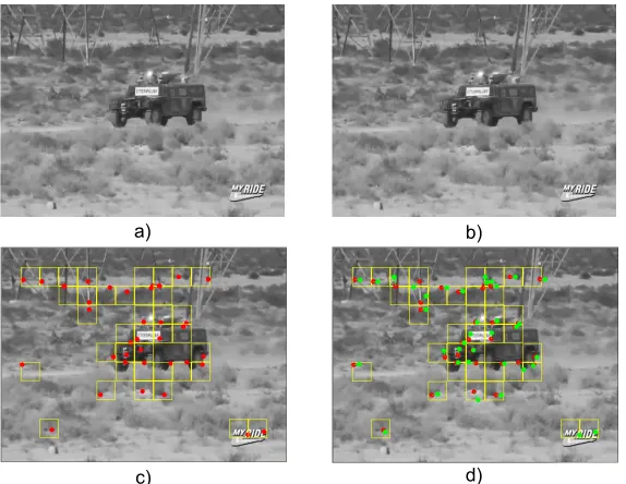
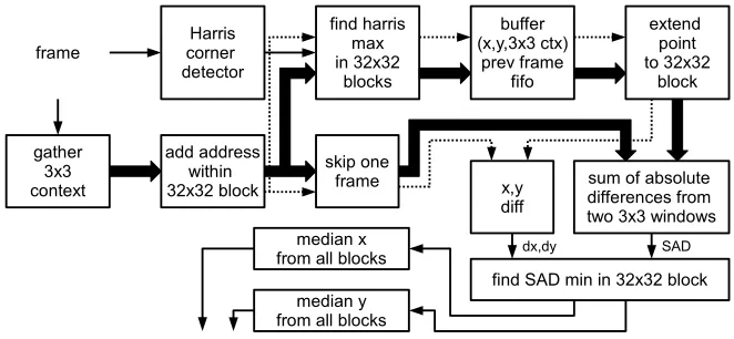
First, a square grid of size 32×32 pixels is overlaid on the image. Within each of the squares the maximum corner detector response is determined. If it exceeds a pre-determined threshold, the point is used to calculate the optical flow. This process takes also place within the 32×32 square. A 3×3 context surrounding the selected pixel is compared with patches of equal size from the previous frame. As a similarity measure the sum of absolute difference (SAD) is used. The final displacement is calculated as the difference between the current location and the best match from the previous one (with minimum SAD distance). The final movement is determined as the median of the resulting optical flow vectors calculated separately for axisxandy. An example motion estimation is presented in Figure 1.
The method has been tested on several video sequences registered with a moving camera. It turned out that after median filtering the obtained displacement vectors were in most cases correct. However, this approach has also some limitations. Firstly, it works properly only in the presence of a sufficient number of interest points on the static part of the scene. In case of a homogeneous background and the lack of an explicit texture it is not possible to reliable determine the displacement using only video processing algorithms. Another difficult situation is the presence of multiple moving objects in the scene. In such case it is possible that over 50% of the detected corners will be associated with moving object, which often differ from the background and have strong edges. Therefore, the calculated median flow will not correspond to the actual camera movement.
It should also be noted that the method has a limited resolution – it determines dis-placements in the range of -32 to 32 for each axis with a precision of one pixel. If the source video sequence will be acquired with 50 or more frames per second, then the up-per maximum displacement of 32 pixels seems to be sufficient in most cases. In contrast, the resolution of 1 pixel is a significant limitation when the camera movement is slow. One possible solution is the use of sub-pixel estimation, which will be investigated in future research.
a) b)
c) d)
Fig. 1.Example of the proposed motion estimation method. a) current frame, b) previous frame, c) result of corner detection in 32×32 context – red dots detected corners, d) result of sparse optical flow; previous location (green) and current location (red). The estimated displacement – [0 , -3]. Image sequence from an old DARPA challenge (video available on-line).
module. This would allow to achieve proper object segmentation with any camera motion, zoom and rotation.
4.2. The Modifications Proposed to the ViBE Algorithm
In the first stage of the research on the ViBE method, the paper [25], in which the authors propose a series of improvements to the algorithm was examined in detail. Unfortunately, implementing most of the presented ideas cause huge difficulties or seems to be impossi-ble in reconfiguraimpossi-ble resources in a pipeline data processing scheme.
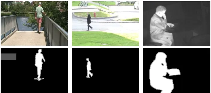
Fig. 2.Sample test images from thechangedetection.netdatabase. Upper row – input im-ages, bottom row column – groundtruth. First column –overpasssequence (movement in back-ground), second column –pedestrians, third column –library(thermal image).
most state of the art algorithms are available on-line (http://www.changedetection.net/). Sample images are presented in Figure 2.
The methodology used in the experiments can be described as follows. The object mask computed by the algorithm was compared with the reference mask (so-called ground truth). Because the ViBE method does not contain a build-in shadow detection proce-dure, only two categories were considered: foreground (movement) and background. The shadow and unknown areas were omitted in the analysis.
The following rates were calculated:
– TP (true positive) – pixel belonging to a foreground object classified as a pixel be-longing to the foreground,
– TN (true negative) – pixel belonging to the background classified as a background pixel,
– FP (false positive) – pixel belonging to the background classified as a pixel belonging to the foreground,
– FN (false negative) – pixel belonging to a foreground object classified as a back-ground pixel.
Then, based on the calculated parameters, two measures were determined: the per-centage of wrong classifications:
P W C= F N+F P
T P +F N+F P +T N ×100% (2)
and precision:
P = T P
T P+F P (3)
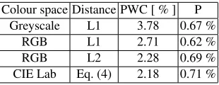
cases the Manhattan (L1) distance metric was used. Additionally for RGB the Euclidean (L2) metric was calculated. In the case of CIE Lab the following formula was used:
dCIELab=α· |LI−LB|+β·(|aI−aB|+|bI−bB|) (4)
where:LI,aI,bI – current pixel in CIE Lab colour space, LB,aB,bB – background model sample in CIE Lab colour space,α,β - weights (in the experiments set toα= 1,
β = 1.5). The analysis of the CIE Lab colour space was performed due to good segmen-tation results obtained in a previous work [17]. The mean performance for the whole test database is summarized in Table 1.
Table 1.Performance of the ViBE algorithm depending on the used colour space.
Colour space Distance PWC [ % ] P Greyscale L1 3.78 0.67 %
RGB L1 2.71 0.62 %
RGB L2 2.28 0.69 %
CIE Lab Eq. (4) 2.18 0.71 %
The only modified algorithm parameter was theRthreshold. It was set experimentally to obtain best P W C andP ratios. The results indicate a slight advantage of the CIE Lab over the RGB (L2 metric and L1 metric) colour space. In addition, the hardware implementation of Equation (4) is much easier than the Euclidean distance calculation (square and the square root operations require large amounts of FPGA logic resources). Therefore, in the final hardware module it was decided to use the CIE Lab colour space, which is a modification to the original proposal from [3].
As post-processing the binary median filter (square window, size7×7) was selected. It is worth noting than adding the filter significantly improves the results obtained by the algorithm. An example is presented in Table 2.
Table 2.The impact of the post-processing median filtering on the algorithms performance. Mean results for the whole database.
Post-processing PWC [ % ] P
none 2.18 0.71 %
median7×7 1.76 0.88 %
4.3. Adapting ViBE to moving camera
camera field of view. However, in this study it was decided to use a solution with lower memory complexity, that involves storing a background model, which size corresponds to the resolution of the processed video stream and realize a dynamic shifting.
The result of camera displacement estimation between adjacent frames is the vector [dx, dy]. On that basis, the background model is shifted according to:
MN(x, y) =MN−1(x+dx, y+dy) (5)
As a result, a part of the model is discarded. For another part it is necessary to perform an initialization. The proposed in paper [2] approach involves filling the bufferM(x, y) with randomly selected samples from the3×3spatial context. Using this solution for initializing the area after the shift operation would be inconvenient, as the displacement values are usually rather small (1 or 2 pixels). In such a case, it is impossible to determine a full3×3 context. Furthermore, the handling of this case, would result in quite com-plex FPGA logic. Therefore, it was decided to use a simpler approach and fill the buffer
M(x, y)with current pixel valuesI(x, y).
The ViBE algorithm is well suited for use in foreground segmentation of sequences registered with a moving camera. This is due to the specific background model, which can consist of samples not only from the actual location, but also from neighbouring ones (originally a 3×3 context). It results in a ”spatial blur” and allows to significantly eliminate two problems related to shifting the background model: inaccurate displacement calculation and geometric distortions related to the movement of the camera’s viewpoint. The described version of ViBE with shifting the background model will be referred to as mViBE.
In addition, to further reduce the negative impact of both factors it was decided to introduce a modification to the background model update rule. Originally, in the ViBE method a conservative approach is used, i.e. an update (modification) is preformed only in locations considered as background. In the proposed solution this condition was weak-ened in case when camera motion is detected (mViBE+).1Then, each of the samples from
the background model may be replaced by a sample from a model in a 3×3 neighbour-hood. The update decision, as well as the selection of samples from the context is random. The mechanism reduces segmentation errors in edge areas, mainly by ”blurring” the back-ground model. It also accelerates penetration of foreback-ground objects into the backback-ground, which should be considered as a negative phenomenon.
Object segmentation in the presence of camera motion was evaluated on 10 sequences. They were divided into three categories:
– no foreground objects, only the camera movement (C1),
– the foreground object moves, as well as the camera (C2),
– the object enters the scene and stops, then the camera starts to move (C3).
Each category allows to evaluate other property of the algorithm. In the first case the ability to properly initiate and model the background is tested. Camera movement should not result in object detection. The second category is typical for PTZ cameras and allows
1
to check the correctness of the displacement estimation in presence of a moving object, as well as the foreground segmentation. In the last case, it is checked to what extent the proposed update rule modification causes penetration of foreground objects into the background model.
For each sequence a selected frame was manually annotated. In this way a reference mask was obtained. Three options were considered: ViBE with no motion compensation (ViBE), ViBE with motion compensation (mViBE) and ViBE with motion compensation and additional update (mViBE+). The evaluation was performed using the same method-ology as in 4.2. Additionally to the precision (P - Equation (3)) and percent of wrong classifications (PWC - Equation (2)), two others measures were used, recall (R):
R= T P
T P+F N (6)
and F-Measure (F).
F = 2·P·R
P+R (7)
The obtained results are summarized in Table 3. Sample frames and foreground object masks from the test dataset are presented in Figure 3.
Table 3.Evaluation of the proposed solution for sequences with camera movement. Mean results for the whole database. C1, C2, C3 – sequence category, P, R F, PWC – classification performance measure. Both explained in text.
C1 C2 C3
P R F PWC P R F PWC P R F PWC
ViBE 0.00 — — 36.66 0.03 0.73 0.06 32.83 0.05 0.85 0.09 30.75 mViBE 0.00 — — 17.64 0.06 0.90 0.12 20.67 0.06 0.75 0.11 23.31 mViBE+ 0.00 — — 0.07 0.74 0.79 0.76 0.75 0.95 0.58 0.72 0.83
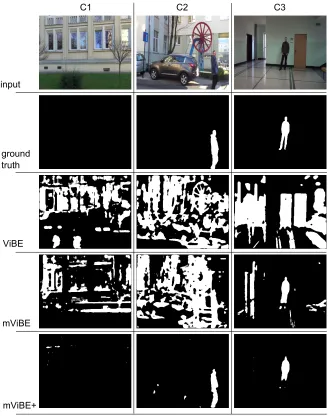
In the category C1 the proposed mViBE+ method works very well. This is evidenced by the low PWC coefficient value and sample results presented in C1 column in Figure 3. The case is specific, as it does not contain any foreground objects in the reference mask. This results in a value of TP = 0 and FP = 0 and the impossibility to compute the param-eters R and F. The other methods, ViBE and mViBE, generate significant errors. Particu-larly interesting is the observation that only shifting the background model (mViBE) does not provide a correct mask. The cause of errors are the previously mentioned, difficult to avoid, inaccuracies when calculating the displacement and distortions associated with the perspective.
method. The results from column C2 in Table 3 show that the value F for mViBE+ is by far the largest.
Sequences from the third category (C3), despite the fairly good performance, show a drawback of the proposed approach. If the object is stationary and there is camera move-ment, an intrusion of foreground pixels into the background model can be observed. This can be confirmed by the visual analysis of frames and the value of the parameter R, which for the C3 set is only 0.58. The intrusion results from the modification of the conservative update approach. When camera movement is detected the whole model is updated, also the locations with stationary objects. These increases the number of false negative. On the other hand, keeping the conservative approach results in much more false detections (false positives). This can be clearly seen in Figure 3, in Column C3 when comparing rows mViBE and mViBE+. Therefore, further research is required to eliminate this phe-nomenon, while retaining the good properties of the approach in cases C1 and C2. The work should concentrate in several areas: improving the camera displacement calculation (e.g. sub-pixel estimation), adding a perspective transform (reduction of errors associated with this phenomenon), improving the background update mechanism, as well as adding feedback from the detection or analysis modules. Especially the last approach seems very promising, as for example object detection using HOG + SVM (Histogram of Oriented Gradients and Support Vector Machines) [14] should allow to significantly reduce or even eliminate the intrusion of foreground objects (detected and recognized as e.g. human or car) into the background model.
5.
Hardware Implementation of the Proposed System
This section discuses the issues related to the hardware implementation of the foreground object segmentation for video sequences registered with a moving camera. In particular, consideration about implementing ViBE in FPGA devices, diagram of the entire system, as well as descriptions of each designed component are presented.
5.1. Considerations About Implementing ViBE in Hardware
One of the main problems with implementing background generation algorithms in hard-ware is providing a quick access to the external memory resources, where the background model is stored [17]. In the case of the ViBE algorithm it is necessary to ensure a transfer rate at the level of 2580 MB/s for a colour video stream with resolution 720×576 and 50 fps (pixel clock 27 MHz). Therefore, a hardware platform equipped with an fast external DDR3 RAM was chosen – the VC707 from Xilinx. A more detailed discussion about this issue is presented in [15].
C1 C2 C3
input
ground truth
ViBE
mViBE
mViBE+
Fig. 3.Sample frames, ground truth and segmentation results for each category.
5.2. Overview of the system
HDMI
camera rgb2grey
rgb2lab
displacement
computation displacementvisualize
mem
ctrl backgroundshift vibe
fifo median
filter visualizemask
LCD monitor
external
DDR3 mem FPGA
FMC DVI IO
Fig. 4.Block diagram of the designed hardware video stream processing system.
add address within 32x32 block frame corner Harris
detector find harris max in 32x32 blocks buffer (x,y,3x3 ctx) prev frame fifo gather 3x3 context skip one frame extend point to 32x32 block
sum of absolute differences from two 3x3 windows
dx,dy SAD
find SAD min in 32x32 block median x
from all blocks
median y from all blocks
x,y diff
Fig. 5.Scheme of the block matching based displacement vector computation module.
5.3. Camera Displacement Computation Module
The block schematic of the camera displacement computation module is presented in Figure 5. It is using the well known block matching technique. Since the displacement of pixels between two frames has to be computed, the module needs to store the information between two frames. For every frame, the Harris-Stephens corner detector is used to ob-tain points which are good to track. Each pixel is assigned a measure which is denoting its probability of being a corner. In the same time, a 3×3 context of a given pixel is gathered (classical two delay line setup is used) and its address within a 32×32 block is computed.
The first step in the camera displacement module is the Harris corner detector [12], presented in Figure 6. It requires determining the so-called Harris matrix:
H =
I2
x⊗G IxIy⊗G
IxIy⊗G Iy2⊗G
(8)
detector. Next, the obtained values are squared or multiplied, which requires 3 multi-plications. The DSP48 multipliers, available in an Xilinx FPGA device are used. Then, a Gaussian smoothing filter is applied for each value (Ix2,IxIy,Iy2). Both Prewitt and Gaus-sian filtering modules are implemented with the use of typical delay line scheme.
The detector response is defined as:
R=det(A)−k·trace2(A) (9)
where:k– a scaling factor (typically 0.02 - 0.2).
Computing the determinant and scaled square trace of the matrix H requires four mul-tiplications, one addition and two subtractions. Too avoid overflow, values after Gaussian filtering where divided by210. The performed experiments proved that this approach does
not affect the final corner detection much and it allows to save hardware resources. Based on the Harris detector output, the most probable point in a 32×32 pixel block is found and its position within given block together with its 3×3 context window (9 pixel values) are stored in a buffer register. If it is the first frame of the sequence, the operation of the whole module is terminated. If however, the FIFO already stores points to match from the previous image, they are read from the buffer and extended to a 32×32 block, so that it can be compared with every 3×3 neighbourhood of all pixels from the new 32×32 block (from current image). The sum of absolute differences is computed and the minimum is found. The position difference of the point to match from the previous frame and its best match from the current frame is obtained ([dx, dy]). After processing all blocks, the displacements are transferred to two modules that compute the median for bothdxanddyseparately.
The proposed module is fully pipelined, only a single BRAM based FIFO is used to store the best points to match (their 3×3 context and position) between two frames. Since only one pixel in the 32×32 block from the previous image is compared to all pixels from the current image 32×32 block, the module requires only one sum of absolute difference unit to allow uninterrupted data flow. Thanks to this, the module is fast and resource efficient. It can however be noticed, that the tracked point may be found outside the 32×32 block between two frames, which makes the matching impossible. This is why, the module also allows to choose a point only from a 16×16 pixel block inside the 32×32 block. However, during experiments it turned out, that such situations are rare (compared to all correct matches) and the median filter efficiently removes this error from final displacement computation.
Median filtering of the displacement vectors is carried out using an histogram based approach. This choice was dictated by two factors: a high maximum number of samples (at the resolution of 720×576 – 396), and the changing number of samples (due to differ-ent response of the corner detector for successive frames). The use of a sorting network,
PIXEL Prewitt X Prewitt Y mult mult mult Ix2
Iy2 Ixy G G G /2^10 /2^10 /2^10 mult mult add mult sub multR(k) D sub R
DIST DIST DIST D D PIXEL MODEL SUM 20 MASK RNG AKT
P0 P0 P0
AKT AKT
AKT
P0 P1 P0
AKT_C AKT
AKT
P0 P0 P0
AKT AKT 720-3 x D
720-3 x D
UPDATED MODEL MEDIAN 7x7 MASK RANDOM
P0 P1
DISPLACEMENT MODELINIT
Fig. 7.Block diagram of the ViBE foreground segmentation module.
which works well in the case of context median filtering (compare section 5.4), would require too much logical resources. In addition, the majority of them would be unused, because normally the number of suitable corners is much less than 396.
Calculating the median value using a histogram is done in two steps. The first creates a histogram of the displacement values ([dx, dy]). The true dual port Block RAM memory available in FPGA devices is used. In parallel, the number of samples is counted. In the second step, data are read from the histogram memory and added together. The median value is the index at which the sum of the histogram values is greater or equal than half of the number of all samples.
5.4. ViBE Foreground Segmentation Module
The ViBE module consists of three sub-modules: one responsible for the initialization of the background model during start or restart of the system, second allowing foreground segmentation and model update and a random number generator.
The first module consists of a3×3context generator, which uses a delay line approach andN(N = 20) multiplexers responsible for the selection of the appropriate sample from the context (1 out of 9). The selected value is then stored in the background model. The multiplexers are controlled using a vector obtained from the random number generation module, thus the model is randomly initialized.
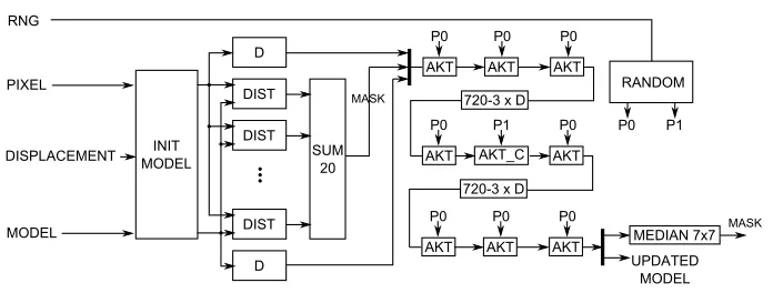
The detailed diagram of the main ViBE foreground segmentation module is presented in Figure 7. The inputs are: RNG (pseudo-random number vector), PIXEL (current pixel in the CIE Lab colour space), MODEL (background model read from the external RAM) and the DISPLACEMENT flag.
a function of a single delay and contains logic that implements the update procedure of neighbouring models. TheACT C module is responsible for update of the model at the central location in the context. It is actually anACTmodule with additional logic used in the proposed update mechanism working in case of camera displacement. The substitu-tion of a background model sample with the current pixel is controlled by the variable P0 (for neighbouring pixels) or P1 (for the central pixel) and depends on the random factor (see Section 3) which is schematically illustrated in the form of theRANDOMmodule.
Pseudo-random number generation (RNG) was realised using the concept described in [23]. It is worth noting that the authors made the VHDL code of different RNG versions available, which easy integrates with the project.
The last stage of the process is the median filtering (MEDIAN 7× 7). The mod-ule consists of two elements: configurable context circuit based on a delay line setup and a sorting unit. The Batcher odd-even merge sort algorithm [13] is used for this task. The required sorting net, supporting the desired number of input elements, is automati-cally generated from previously developed software version of the algorithm, which stores the input and output arguments of consecutive comparisons. This information is used by a Matlab script, which is generating a VHDL file with the right comparator instances and connections between them. Such approach allows an automatic generation of a median filter that can support various window sizes and different data widths and signedness.
The updated model is stored in the external RAM and the foreground mask is dis-played on the LCD screen.
5.5. Auxiliary Modules
A few other auxiliary modules were used in the system:
– rgb2grey– colour space conversion from RGB to greyscale, since the displacement estimation module works on intensity only,
– rgb2lab– colour space conversion from RGB to CIE lab. More details in [17],
– mem ctrl– a DDR3 memory controller with additional FIFOs. More details in [17],
– shift background– module responsible for shifting the background model according to the calculated displacement[dx, dy],
– visualize displacement– module allows imposing bars, which correspond with the calculated displacement, on the display,
– visualize mask– module allows to visualize the foreground mask on the LCD monitor.
5.6. System integration
Fig. 8.Working system. The operator rotates the HDMI camera, so that the moving person (in the background) is always located in the centre of the image (the overlaid red line indicates the camera direction). The foreground mask (segmentation result) is displayed on the LCD screen. The FPGA development board is visible in front of the LCD.
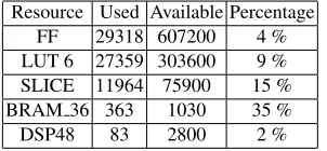
controller, the BRAM 36 (Block RAM) utilisation is quite high. On the other hand, only 15 % of slices are used by the system. Therefore, it is possible to add other image process-ing and analysis modules e.g. trackprocess-ing, detection or recognition. The compatibility of the hardware module with the software C++ model was confirmed using the ISim simulation tool. The working system is presented in Figure 8.
The HDMI camera operator (person on the right) tracks (keeps in the centre of the frame) the walking person. Both images were recorded at different camera positions, as indicated by the red lines. The video stream from the camera has 720×576 pixels res-olution and a frame rate of 50 fps. In is transmitted to the FPGA board (below the LCD screen), where it is processed in real time. The foreground segmentation results are dis-played on the LCD monitor.
Table 4.FPGA resource usage – Xilinx Virtex 7 (XC7VX485T) FPGA device.
Resource Used Available Percentage FF 29318 607200 4 % LUT 6 27359 303600 9 % SLICE 11964 75900 15 % BRAM 36 363 1030 35 %
DSP48 83 2800 2 %
6.
Conclusion
The system consist of many elements, of which the most important are: the Harris-Stephens corner detector, a sparse optical flow calculation method utilizing a correlation approach in 32×32 pixels window, histogram based median filtering of flow vectors, background modelling with the ViBE method and median filtering of the foreground ob-ject mask. Moreover, a modification to the background update rule in the ViBE algorithm, that significantly improves its performance in the case of camera displacement, was pro-posed
All modules were implemented in VHDL or Verilog hardware description language, integrated and tested on the hardware platform VC707 with Virtex 7 FPGA device from Xilinx. A HDMI camera was the source of a 720×576 @ 50 fps video stream, which was then processed in real-time in the FPGA and the foreground mask was displayed on the monitor. The systems performs over 60 GOPS/s with a power dissipation below 4 W. To our best knowledge, this is the first hardware implementation of this kind of video processing system.
In the future, further work on the system in the following areas would be advisable: improving the displacement estimation through the use of more sophisticated interest points detectors (SIFT, SURF) and features used in tracking (e.g. supporting SAD with Census transform), replacing the median filtering with RANSAC algorithm, the addition of sub-pixel estimation, adding projective transform, developing a better model update rule and adding a feedback from a detection module. The improved system should have a very good segmentation accuracy, especially in the case of moving human silhouettes.
Implementing the algorithm on a specialized hardware system allows to obtain real-time performance in a small embedded device with has a low power consumption. In ad-dition the reprogramability of FPGAs enables the continuous development and improve-ment of the design. The proposed solution can be used in advanced, automated video surveillance systems and other application which require a reliable foreground mask and real-time image processing, especially for a moving camera installed on autonomous ve-hicles or in driver assistance systems.
Acknowledgments.This work was supported by the AGH University of Science and Technology grants no. 15.11.120.330 (first author), 15.11.120.356 (second author) and 11.11.120.612 (third author).
References
1. Amri, S., Barhoumi, W., Zagrouba, E.: A robust framework for joint background/foreground segmentation of complex video scenes filmed with freely moving camera. Multimedia Tools and Applications 46(2-3), 175–205 (2010)
2. Barnich, O., Van Droogenbroeck, M.: ViBE: A powerful random technique to estimate the background in video sequences. In: IEEE International Conference on Acoustics, Speech and Signal Processing (ICASSP). pp. 945–948 (2009)
3. Barnich, O., Van Droogenbroeck, M.: ViBE: A universal background subtraction algorithm for video sequences. IEEE Transactions on Image Processing 20(6), 1709–1724 (2011)
5. Elhabian, S.Y., El-Sayed, K.M., Ahmed, S.H.: Moving Object Detection in Spatial Domain using Background Removal Techniques - State-of-Art. Recent Patents on Computer Science 1, 32–34 (2008)
6. Gallego, J., Pardas, M., Solano, M.: Foreground objects segmentation for moving camera sce-narios based on SCGMM. In: Computational Intelligence for Multimedia Understanding. Lec-ture Notes in Computer Science, vol. 7252, pp. 195–206. Springer Berlin Heidelberg (2012) 7. Genovese, M., Napoli, E.: An FPGA-based real-time background identification circuit for
1080p video. In: Eighth International Conference on Signal Image Technology and Internet Based Systems (SITIS). pp. 330–335 (2012)
8. Genovese, M., Napoli, E.: FPGA-based architecture for real time segmentation and denoising of HD video. Journal of Real-Time Image Processing 8(4), 389–401 (2013)
9. Genovese, M., Napoli, E.: ASIC and FPGA implementation of the gaussian mixture model algorithm for real-time segmentation of high definition video. IEEE Transactions on Very Large Scale Integration (VLSI) Systems 22(3), 537–547 (2014)
10. Gorgon, M.: Parallel performance of the fine-grain pipeline FPGA image processing system. Opto-Electronics Review 20(2), 153–158 (2012)
11. Goyette, N., Jodoin, P., Porikli, F., Konrad, J., Ishwar, P.: Changedetection.net: A new change detection benchmark dataset. In: IEEE Computer Society Conference on Computer Vision and Pattern Recognition Workshops (CVPRW). pp. 1–8 (2012)
12. Harris, C., Stephens, M.: A combined corner and edge detector. In: In Proceedings of Fourth Alvey Vision Conference. pp. 147–151 (1988)
13. Knuth, D.: The Art of Computer Programming, Volume 3: Sorting and Searching. Addison-Wesley (1998)
14. Komorkiewicz, M., Kluczewski, M., Gorgon, M.: Floating Point HOG Implementation for Real-Time Multiple Object Detection. In: 22nd International Conference on Field Pro-grammable Logic and Applications (FPL). pp. 711–714 (2012)
15. Kryjak, T., Gorgon, M.: Real-time implementation of the ViBe foreground object segmentation algorithm. In: Federated Conference on Computer Science and Information Systems (FedC-SIS). pp. 591–596 (2013)
16. Kryjak, T., Komorkiewicz, M., Gorgon, M.: Hardware implementation of the PBAS foreground detection method in FPGA. In: Proceedings of the 20th International ConferenceMixed Design of Integrated Circuits and Systems (MIXDES). pp. 479–484 (2013)
17. Kryjak, T., Komorkiewicz, M., Gorgon, M.: Real-time background generation and foreground object segmentation for high defnition colour video stream in FPGA device. Journal of Real-Time Image Processing 9(1), 61–77 (2014)
18. Lucas, B., Kanade, T.: An iterative image registration technique with an application to stereo vision. In: In Proceedings of the International Joint Conference on Artificial Intelligence. pp. 674– 679 (1981)
19. OpenCV: Website:http://opencv.org/(last acess: April 2014) (2013)
20. Rodriguez-Gomez, R., Fernandez-Sanchez, E., Diaz, J., Ros, E.: Codebook hardware imple-mentation on FPGA for background subtraction. Journal of Real-Time Image Processing pp. 1–15 (2012)
21. Rodriguez-Gomez, R., Fernandez-Sanchez, E., Diaz, J., Ros, E.: FPGA Implementation for Real-Time Background Subtraction Based on Horprasert Model. Sensors 12(1), 585–611 (2012)
22. Smith, S.: ASSET-2: real-time motion segmentation and shape tracking. In: Proceedings of the Fifth International Conference on Computer Vision. pp. 237–244 (1995)
24. Toyama, K., Krumm, J., Brumitt, B., Meyers, B.: Wallflower: principles and practice of back-ground maintenance. In: The Proceedings of the Seventh IEEE International Conference on Computer Vision. vol. 1, pp. 255–261 (1999)
25. Van Droogenbroeck, M., Paquot, O.: Background subtraction: Experiments and improvements for vibe. In: IEEE Change Detection Workshop. pp. 32–37 (2012)
26. Wang, Y.K., Chen, H.Y.: The design of background subtraction on reconfigurable hardware. In: Eighth International Conference on Intelligent Information Hiding and Multimedia Signal Processing (IIH-MSP). pp. 182–185 (2012)
27. Yao, B., Cai, X., Wei, B.: Long-term background reconstruction with camera in motion. In: 2nd International Congress on Image and Signal Processing (CISP). pp. 1–5 (2009)
Tomasz Kryjakreceived MSc degree in Automatics and Robotics in 2008 and PhD de-gree in Automatics and Robotics in 2013, both from AGH University of Science and Technology in Krakow, Poland. From 2008 on permanent position at the Department of Automatics and Biomedical Engineering AGH-UST, currently Assistant Professor. His re-search is focused on image processing, analysis and recognition, advanced video surveil-lance systems, reconfigurable FPGA systems, hardware algorithm acceleration and soft-ware/hardware co-design. He is the author of more than 30 scientific papers.
Mateusz Komorkiewiczreceived MSc degree in Automatics and Robotics in 2010 from AGH University of Science and Technology in Krakow, Poland. In the same year he started PhD studies at the AGH-UST under the supervision of Prof. Marek Gorgon. His main area of research is machine and computer vision with a special interest in accelerat-ing vision algorithms usaccelerat-ing FPGA devices.
Marek Gorgonreceived MSc degree in Electronics and Control Engineering in 1988, PhD in Automatic Control and Robotics in 1995 and DSc (habilitation) in 2007 all three from AGH University of Science and Technology in Krakow, Poland. From 1994 on per-manent position at the Department of Automatics and Biomedical Engineering AGH-UST, currently Associate Professor. His research interests include image processing, re-configurable devices and systems architecture, and FPGA devices and applications.