(UDC: 616.132.2-089.819:004.94)
Computer modeling of restenosis and heating stent thermal effects in the
coronary artery
N. Zdravkovic-Petrovic1, D. Nikolic2, Z. Milosevic2, E. Themis3, O. Parodi4 and N. Filipovic2
1 Faculty of Medical Science, University of Kragujevac, Kragujevac, Serbia 2
Faculty of Engineering, University of Kragujevac, Kragujevac, Serbia 3 University of Ioannina, Ioannina, Greece
4 National Research Council Pisa, Italy
Abstract
The understanding and the prediction of the evolution of atherosclerotic plaques either into vulnerable plaques or into stable plaques are very important for the medical community. Stents in the coronary arteries are routinely used in the management of patients with angina or myocardial infarction where percutaneous coronary intervention is the clinically appropriate procedure.
In this study we analysed stent deployment in the specific patient and simulation of the temperature distribution for heating stent in the final position. Effective stress analysis in the stent and arterial wall may give better understanding of the process of restenosis. We did geometrical reconstruction of the coronary artery from combination of biplane angiography and intravascular ultrasound. Finite element method computations were performed to simulate the deployment of a stent and heating stent thermal effects in the coronary model.
In the arterial wall the maximal effective stress are found behind the stent and in the regions where the arterial wall was thinner. Temperature distribution during virtual stent heating shows maximal temperature around 48C. It could be desired for the smooth muscle cells (SMC) inside the plaque which can die in apoptosis. These results suggest that we can make heating of the implanted stent to prevent restenosis.
Keywords: Stenosis, stent deployment, computer modeling, biomechanical stresses
1. Introduction
Serious problem of ischemia to tissues is caused with narrowing and hardening of arteries. Today treatments for blocked coronary arteries include bypass surgery, angioplasty, and stenting. Vascular stent is a small metal tube, which is inserted inside the artery and it has a role to change narrowing of the artery. The process of restenosis which is not desirable is caused by neointimal hyperplasia where an inflammatory phase, a granulation or cellular proliferation phase, and a phase of extracellular matrix protein synthesis are included (Edelman E.R. 1998).
desirable temperature distribution inside the arterial wall around the stent in order to induce the vascular SMC apoptosis. Electromagnetic field can be used for significantly heating NiTi stent and the heating temperature can be adjusted by changing the voltage and heating time (Le et al., 2005).
There are studies for modeling and design of stents computationally, as well as stent design affects restenosis (Kastrati et al., 2001; Rogers et al., 1995; Rogers et al., 1999). For modeling of balloon expansion with stent and artery contact linear elastic models are implemented using a 2- dimensional model by Rogers et al., 1999.
Lally and colleagues (Lally et al., 2005) calculated the stent-artery interaction of commercially available stents on an idealized stenosed artery. Holzapfel et al., 2004, modeled the balloon expansion of a full three-dimensional anisotropic diseased artery.
In this study we analyze stent deployment and heating stent thermal effect on the arterial wall in the coronary artery. The paper is organized as following. Firstly basic equations and finite element methodology for solving blood flow, nonlinear arterial wall and stent interaction with arterial wall are presented. Some results for stress analysis of the arterial wall and stent are shown. Finally, computational results are discussed and summarized.
2. Methods
2.1 3D image reconstruction
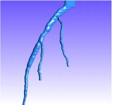
Three-dimensional coronary artery reconstruction is provided from IVUS and Angiography (Plissiti et al., 2004; Papadogiorkaki et al., 2007; Wahle et al., 1999; Laban et al., 1995; Slager et al., 2000). Two end – diastolic angiographic images are used to predict the catheter path. The artery path is approximated with cubic B – Splines and the catheter path is evolved by the intersection of two splines. IVUS frames are collected at the peak of R wave and by using deformable models and Neural Networks the lumen and outer vessel border are identified.
Fig. 1. Three-dimensional reconstructed model of an arterial tree. The location of the stenotic
2.2 Methods of blood flow modeling in large blood vessels
The blood can be considered as an incompressible homogenous viscous fluid for flow in large blood vessels. Also, the laminar flow is dominant in physiological flow environment. Therefore, the fundamental laws of physics which include balance of mass and balance of linear momentum are applicable here. These laws are expressed by continuity equation and the Navier-Stokes equations.
We here present the final form of these equations to emphasize some specifics related to blood flow. The incremental-iterative balance equation of a finite element for a time step ‗n‘ and equilibrium iteration ‗i‘ has a form
(1) (1) 1 ( 1) ( )
( )
1 ( 1) 1
1 ( 1)
1 1 1 1 0 0 0 i i
n i i
vv vp i T
blood vp
n i n n
n i vp ext n T vp t t t
M K K V
P
K 0
M K K V M V
F
P K
(1)
where n1V( 1)i n1P( 1)i are the nodal vectors of blood velocity and pressure, with the increments in time step V( )i and P( )i (the index ‗blood‘ is used to emphasize that we are considering blood as the fluid); t is the time step size and the left upper indices ‗n‘ and ‗n+1‘ denote start
and end of time step; and the matrices and vectors are defined in (Kojic et al., 2008). Note that the vector n1Fext(i1) of external forces includes the volumetric and surface forces. In the assembling of these equations, the system of equations of the form (1) is obtained, with the volumetric external forces and the surface forces acting only on the fluid domain boundary (the surface forces among the internal element boundaries cancel).
The specifics for the blood flow are that the matrix n1K(i1) may include variability of the viscosity if non-Newtonian behavior of blood is considered. We have that
( 1) ( 1) ( 1) , ,
ˆ
i i i
KJ mk KJ K j J j
mk V
K K N N dV
(2)where
(i1) corresponds to the constitutive law for the last known conditions (at iteration ‗i1‘). In case of use of the Cason relation (2), the second invariant of the strain rate (i 1) II
D is to be evaluated when computing
(i1).We note here that the penalty method can also be used, as well as the ALE formulation in case of large displacements of blood vessel walls (Filipovic et al., 2006).
In addition to the velocity and pressure fields of the blood, the distribution of stresses within the blood can be evaluated. The stresses tij at time ‗t‘ follow from
t t t
ij p ij ij
(3)
where
, ,
t t t
ij vi j vj i
(4)
Further, the wall shear stress at the blood vessel wall is calculated as:
t t t vt
n
(5)
where tvt denotes the tangential velocity, and n is the normal direction at the vessel wall. Practically, we first calculate the tangential velocity at the integration points near the wall surface, and then numerically evaluate the velocity gradient t /
t
v n
; finally, we determine the viscosity coefficient t
using the average velocity at these integration points. In essence, the wall shear stress is proportional to the shear rate at the wall, and the blood dynamic viscosity . For a pulsatile flow the mean wall shear stress within a time interval T can be calculated as (Taylor et al., 1998)0
1T
T t
mean ndt
T
(6)Another scalar quantity is a time-averaged magnitude of the surface traction vector, calculated as
0
1T
T t
mag dt
T
t (7)where the vector tt is given by the Cauchy formula.
2.3 Modeling the deformation of blood vessels
Blood vessel tissue has complex mechanical characteristics. The tissue can be modeled by using various material models, from linear elastic to nonlinear viscoelastic. We here summarize the governing finite element equations used in modeling wall tissue deformation with emphasis on implementation of nonlinear constitutive models.
The finite element equation of balance of linear momentum is derived from the fundamental differential equations of balance of forces acting at an elementary material volume. In dynamic analysis we include the inertial forces in this equation according to. Then, by applying the principle of virtual work
w ext
MU B U KU F (8)
Here the element matrices are: M is mass matrix; Bw is the damping matrix, in case when the material has a viscous resistance; K is the stiffness matrix; and Fext is the external nodal force vector which includes body and surface forces acting on the element. By the standard assembling procedure, the dynamic differential equations of motion are obtained. These differential equations can further be integrated in a way described, with a selected time step size
t
. The nodal displacements n1U at end of time step are finally obtained according to equation:
1 1
ˆ n n ˆ
tissue
K U F (9)
problem is linear: displacements are small, the viscous resistance is constant, and the material is linear elastic.
In many circumstances of blood flow the wall displacements can be large, as in case of aneurism or hart, hence the problem becomes geometrically nonlinear. Also, the tissues of blood vessels have nonlinear constitutive laws, leading to materially-nonlinear FE formulation. Therefore, the approximations adopted to obtain equation (9) may not be appropriate. For a nonlinear problem, instead of (9) we have the incremental-iterative equation
1ˆ( 1) ( ) 1ˆ( 1) 1 int( 1)
n i i n i n i
tissue
K U F F (10)
where ( )i
U are the nodal displacement increments for the iteration ‗i‘, and the system matrix
1ˆ( 1) n i
tissue
K , the force vector n1ˆ(i1)
F and the vector of internal forces n1Fint(i1) correspond to the previous iteration.
We here emphasize the material nonlinearity of blood vessels which is used in further applications. As presented, the geometrically linear part of the stiffness matrix,
n 1
(i 1)L tissue
K , and
nodal force vector, n1Fint(i1), are defined in equation:
1
( 1) 1 ( 1)
1 int
( 1) 1 ( 1),
i i
n T n i n T n i
L tissue L tissue L L
V V
dV dV
K B C B F B σ (11)
where the consistent tangent constitutive matrix 1 ( 1) n i
tissue
C of tissue and the stresses at the end of
time step 1 ( 1) nσi
depend on the material model used. Calculation of the matrix 1 ( 1) n i
tissue
C and the
stresses
1 ( 1) nσi
for the tissue material models used in further applications. In each of the subsequent sections we will give the basic data about the models used in the analysis.
3. Results
In order to perform computer modeling of the combined effects of the surrounding arterial wall and inner forces of blood and stent deployment against the arterial wall, a 3D reconstruction from IVUS and angiography was derived.
The FE model consists of the solid domain and the fluid domain (Fig. 1). The solid domain consists of: stent and arterial wall. Fluid and solid domains are modeled using 3D-8-node finite elements.
Boundary conditions for the solid surrounding the artery are as follows. It is assumed that the first and last sections do not move axially, hence all FE element nodes in these cross-sections are axially restrained.
It is also assumed that the wall material is orthotropic nonlinear elastic, and the Fung material model is adopted (Fung et al., 1979). The strain energy function is defined. The material parameters c a a, 1, 2,a4 are determined using data fitting procedure from (Kojic et al., 2008). Material parameters obtained from the fitting procedure are:
1 2 40.7565 , 0.166, 0.084, 0.045
c MPa a a a (12)
60000 0.3
520 750 550 200
250 20 7.5% 0 /
AS AS SA SA
s f s f
AS SA
L
E MPa
C MPa K
(13)
where all
- and
-parameters are in [MPa]. Material parameters of blood are: density3 3
1.05 10 g mm/
and dynamic viscosity
33.675 10 Pa s
.
According to the boundary conditions and loads mentioned above, the numerical analysis of the material behavior of this complex model is performed. To examine different loading conditions, we apply hemodynamic flow as well as stent deployment procedure at the arterial wall.
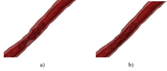
The stent is loaded by an internal uniform radial pressure linearly varies from zero to 1 MPa. Due to the artery incompressibility requirement and to avoid locking-problems, 8-node brick elements are used in all the analyses (Kojic et al., 2008). In particular, in the simulations we use up to 232214 elements and 257532 nodes, resulting in 666354 variables. The interaction between the expanding stent and the artery is described as contact between deformable surfaces. As contact conditions, we set finite sliding, no-friction, with the constraint enforced by a Lagrange multiplier method. The stenotic segment of the artery which was examined before and after stent deployment is presented in Fig. 2.
a) b)
Fig. 3. Effective stress distribution inside the arterial wall after stent deployment. The units are in MPa.
Blood flow analysis was performed by finite element method described in the methods section. Shear stress distribution before and after stent deployment is shown in Fig. 3. It can be seen that stent reduce wall shear stress significantly after deployment which is caused by opening the artery and reducing the narrowing.
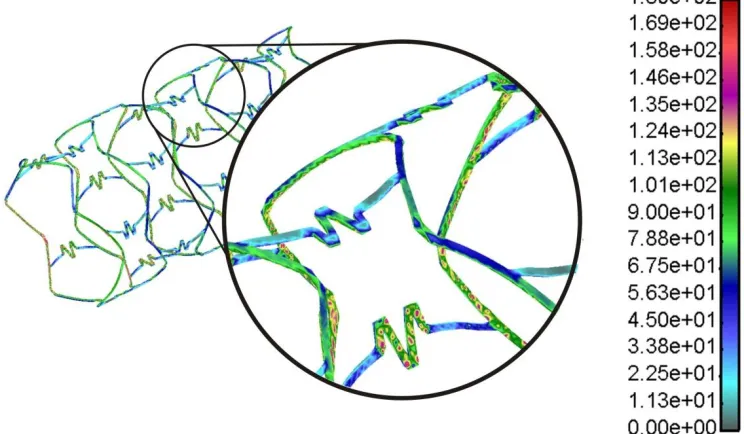
Fig. 4. Effective von Mises stress distribution for inflation pressure of 1 MPa. The units are in
The effective von Mises stress distribution in the stent is presented in Fig. 4. It can be observed that highest stresses are located near the connectors between the stent struts. These parts are subjected to plastic deformation with maximal stress around 180 MPa.
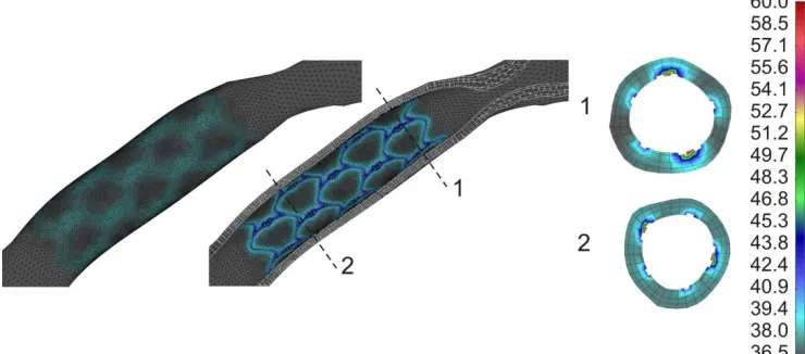
Fig. 5. Effective stress distribution in the two different cross-section locations inside the arterial wall at the end of stent deployment.
The effective stress distribution in the arterial wall at the two different cross-section locations at the end of stent deployment with maximum deployment pressure is shown in Fig. 5. It can be observed that higher stress exists when wall thickness is reduced during deployment procedure.
Fig. 6. Temperature distribution inside the arterial wall after stent deployment and heating.
4. Discussion and conclusion
Better understand of stent deployment procedure and arterial wall response as well as optimal stent design can be obtained using computer simulation.
Acknowledgments
This study was funded by a grant from FP7-ICT-2007 project (grant agreement 224297, ARTreat) and grants from Serbian Ministry of Education and Science III41007 and ON174028.
Извод
Компјутерско моделирање рестенозе и термалних ефеката стента који
се загрева у коронарној артерији
Natasa Zdravkovic-Petrovic1, Dalibor Nikolic2, Zarko Milosevic2, Exarchos Themis3,
Oberdan Parodi4 and Nenad Filipovic2
1
Faculty of Medical Science, University of Kragujevac, Kragujevac, Serbia 2 Faculty of Engineering, University of Kragujevac, Kragujevac, Serbia 3 University of Ioannina, Ioannina, Greece
4 National Research Council Pisa, Italy
Резиме
Разумевање и предвиђање развоја атеросклеротских плака у нестабилне или у стабилне наслаге веома је важно за медицинску заједницу. Стентови у коронарним артеријама рутински се користе за третман пацијената са ангином или инфарктом миокарда где је перкутана коронарна интервенција клинички прикладан поступак.
У овој студији анализирали смо поступак уградње стента код пацијента и симулацију расподеле температуре за загревање стента у крајњем положају. Анализа ефективног напона у стенту и зиду артерије може допринети бољем разумевању процеса рестенозе.
Извршили смо геометријску реконструкцију коронарне артерије комбиновањем бипланарне ангиографије и интраваскуларног ултразвука. Извршени су прорачуни методом коначних елемената како би се симулирала уградња стента и термални ефекти стента који се загрева у коронарном моделу.
У артеријском зиду максимални ефективни напон забележен је иза стента у регијама где је зид артерије тањи. Расподела температуре током виртуелног загревања стента показује максималну температуру око 48C. Ово може бити пожељно за глатке мишићне ћелије (SMC) унутар плака које могу изумирати у апоптози. Резултати сугеришу да је могуће спречити процес рестенозе загревањем уграђеног стента.
Кључне речи: Стеноза, уградња стента, компјутерско моделирање, биомеханички напони
References
Burd R., Dziedzic Y.S., Xu Y., Caligiuri M.A. (1998). J. Cell Physiol., Vol.177, 137.
Edelman E.R., (1998). Rogers C: Pathobiologic responses to stenting. Am J Cardiol, 81(7A), 4E-6E.
Filipovic N., Mijailovic S., Tsuda A., Kojic M., (2006). An Implicit Algorithm Within The Arbitrary Lagrangian-Eulerian Formulation for Solving Incompressible Fluid Flow With Large Boundary Motions, Comp. Meth. Appl. Mech. Engrg., 195, 6347-6361.
Fung, Y.C., Fronek K., Patitucci P., (1979). Pseudoelasticity of arteries and the choice of its mathematical expression, Am. J. Physiol., 237, 620-631.
Holzapfel, G. A., Sommer, G., Regitnig, P., (2004). Anisotropic mechanical properties of tissue components in human atherosclerotic plaques. Journal of Biomechanical Engineering 126, 657-665.
Kastrati, A., Mehilli, J., Dirschinger, J., Pache, J., Ulm, K., Schuhlen, H., Seyfarth, M., Schmitt, C., Blasini, R., Neumann, F.J., Schomig, A., (2001). Restenosis after coronary placement of various stent types. The American Journal of Cardiology, 87, 34-39.
Kojic M., Filipovic N., Stojanovic B., Kojic N., (2008). Computer Modeling in Bioengineering: Thеoretical Background, Examples and Software. John Wiley and Sons, Chichester, England.
Laban, M., Oomen, J., Slager, C., Wentzel, J., Krams, R., Schuurbiens, J., (1995). ANGUS: a New Approach to Three-Dimensional Reconstruction of Coronary Vessels by Combined Use of Angiography and Intravascular Ultrasound, In: Proc. conf. CinC Vienna.
Lally, C., Dolan, F., Prendergast, P.J., (2005). Cardiovascular stent design and vessel stresses: a finite element analysis. Journal of Biomechanics 38, 1574-1581.
Li C., Zheng Y. Zhao L., (2005). Heating NiTi Stent in magnetic fields and the thermal effect on smooth muscle cells, Key Engineering Materials 288-289, 579-582.
Papadogiorkaki, M., Chatzizisis, Y., (2007). Automated IVUS Contour Detection usingIntensity Features and Radial Basis Function Approximation, IEEE International Symposium on Computer Based Medical Systems.
Plissiti, M., Fotiadis, D., Michalis, L., Bozios, G., (2004). An Automated Method for Lumen and Media-Adventitia Border Detection in a Sequence of IVUS Frames,‖ IEEE trans on Inf Tech. in Biomed, 8, 131-141.
Rogers, C., Edelman, E. R., (1995). Endovascular stent design dictates experimental restenosis and thrombosis. Circulation 91, 2995-3001.
Rogers, C., Tseng, D.Y., Squire, J.C., Edelman, E.R., (1999). Balloon-artery interactions during stent placement: a finite element analysis approach to pressure, compliance, and stent design as contributors to vascular injury. Circulation Research 84, 378-383.
Slager, C., Wentzel, J., Schuurbiers, J., Oomen, J., Kloet, J., Krams, R, (2000). True 3-Dimentional Reconstruction of Coronary Arteries in Patients by Fusion of Angiography and IVUS (ANGUS) and its Quantitive Validation‖ Circulation, 102, 511-6
Taylor C.A., Hughes T.J.R., Zarins C.K., (1998). Finite element modeling of blood flow in arteries, Comp. Meth. Appl. Mech. Engrg., 158, 155-196.
Wahle, A,, Prause, G., Dejong, S., Sonka, M., (1999). Geometrically correct 3-D reconstruction of intravascular ultrasound images by fusion with biplane angiography – methods and validation,‖ IEEE Trans Med Imaging, 18, 686-98.