e-ISSN: 2250-3021, p-ISSN: 2278-8719 Vol. 3, Issue 7 (July. 2013), ||V2 || PP 13-23
Experimental Study on Beam- Column Joint with Fibres under
Cyclic Loading
Romanbabu M. Oinam, Choudhury.A.M, And Laskar A I
Abstract: - In earthquake resistant design, it is important to ensure the ductility in the structure, i.e., the structure should be able to deform inelastically and dissipate energy without causing collapse. In frame structure, the bending moment and shear force are maximum in the junction area. So beam-column joint is one of failure zone. Among the beam-column joint, exterior joint behaves more critically than the interior joint during the occurrence of earthquake. Many researchers have done research on joints using different techniques, materials and introduced many repairing methods to enhance the resisting capacity of joints. From literature, it has been observed that Polypropylene and Steel fibres have enhanced many desirable properties of concrete. Hence, these fibrous materials can be introduced in these joints to enhance joint property. Polypropylene is a plastic polymer and Steel fibres are made from prime quality hard-drawn steel wire to ensure high tensile strength and close tolerances. Literature survey on these fibres does not reflect any prominent work carried out on beam-column joint using these fibres, particularly under cyclic loading. Hence, in the present research these fiber materials were used for beam column joint to observe the change/enhancement in the strength, stiffness, ductility and energy dissipation capacity of the joints. In the present work, three one third (1/3 rd) scaled beam-column joints have been caste with plain RC and RC fibres. All the specimen has been detailed by the provisions of IS: 13920 incorporating similitude requirements. The specimens were tested by applying cyclic load. The tests were conducted by using servo hydraulic actuator (MTS made) of 100kN capacity. The recorded data were plotted to draw hysteresis loop. The result were compared in various plot like envelope curve, stiffness, energy dissipate and ductility. It was observed that performance of fibre specimens in term of all the above parameters were better than the plain specimen.
Keyword: - Fibre, Beam-column joint, envelope curve, stiffness, energy dissipates and ductility.
I. INTRODUCTION
From pre-historic era earthquake is the natural major destruction elements to human beings. During earthquake most of the structure failure occurred in joint area, so beam-column joint is one of the major failure zone. Hanson and Connor (1967) [1] has been conducted first experimental study of beam-column joint under simulated earthquake loading in the United States. They were reported regarding moment capacities at first yield of reinforcement, ultimate moment and ductility of the assemblies, maximum beam deflection and anchorage bond stresses of the beam reinforcements. Megget and Park (1971) [2] performed experimental study of external beam-column joint under seismic loading, and low beam-column axial load. Authors reported that the joints of the specimens were not adequately reinforced against large shear stresses at inelastic loading condition. Scribner and Wight (1980) [3] conducted experimental study the strength decay in eight half scale and six full scale RC exterior beam-column joint under load reversals to investigate the effect of intermediate longitudinal reinforcement on shear deterioration of flexural members subjected to repeated type of loading. Durrani and Wight (1985) [4] investigated experimental study on performance of an interior Beam-Column joint under earthquake type loading which had less joint reinforcement than recommended by ACI-ASCE Committee 352. They reported that the joint shear stress had a pronounced effect on the behaviour at large ductility levels and the joint hoop reinforcement. Abdel-Fattah and Wight (1987) [5] investigated, twelve full-size interior beam-column sub-assemblages were tested under cyclic loads to study relocating of plastic hinging zones for earthquake-resistant design of RC buildings. The authors concluded that the performance of extra reinforcement in the joint could help in successfully relocating the plastic hinge away from the column face. Ehsani and Alameddine (1991) [6] investigated the behaviour of corner joint, and they were used high strength concrete. In their study twelve specimen were tested in order to examine the recommendations of ACI-ASCE Committee 352 on the design of high-strength ductile moment resisting beam-column joints. They reported that the recommendations which were developed for normal strength concrete could not be applied to high-strength concrete frame. Murty et al.(2003)
[7]
envelope curve, stiffness, ductility, ultimate load were improve in column strong specimen than the column weak specimen.
ML Gambhir [9] has reported polypropylene and steel fibre is easily available polymer (C3H6) and hard-drawn
steel wire fibres. Its resist most of chemicals, and it would be cementing matrix which would deteriorate first under aggressive chemicals attack. Polypropylene has high melting point, even working temperature is 100 oC also not affected. Polypropylene and steel fibre avoid micro cracks, improve closed surface of concrete, reduced bleeding, improves concrete’s resistance to plastic shrinkage cracking, better concrete durability and reduce surface dusting, improve mix cohesiveness, reduce segregation of the mix, improves water migration. C.D. Johnston (1974) [11] investigated effect of steel fibre in reinforced concrete. He reported that crack, ductility, energy absorption and ability to withstand repeatedly applied or impact loading was increased by the steel fibre. N. Ganesan et al. (2007) [12] experimentally investigated ten steel fibre specimen of external beam-column joint under cyclic load. They reported that all specimen undergoes large deformation without developing wider cracks and decrease the rate of stiffness degradation. Machine Hsie et al. (2008) [14] has reported mechanical properties of polypropylene hybrid fibre compare with pure compressive strength of concrete. They observed that polypropylene specimen was increase compressive strength, tensile strength, modulus of rupture and toughness index than the pure concrete. Rana A. Mtasher et al. (2011) [15] has been performed using different percentage of polypropylene fibre on mix concrete to determine the compressive and flexural strength conducting a series of test, and they have reported mechanical properties polypropylene fibre relatively high.
Literature survey showed that although extensive experimental investigations were carried out to understand the behaviour of beam-column joints, yet no record could be found covering fibres at Beam-Column joint. The research was initiated to observe the change in strength, displacement ductility, energy dissipation etc due to strengthening by fibre.
II. SELECTION OF THE SPECIMEN
The deflected shape of a frame under the action of lateral loading is shown in Figure.1(a) where the points of contraflexure lie at the mid-points of beams and columns. Further, the free body diagram of an external beam-column sub-structure assembly is shown in Figure.1(b). It comprises of half of a beam-column at top and bottom as well as half of a beam. It may be noted that the symmetric boundary condition should be maintained at both the ends of column for isolation of a single unit of beam-column joint.
(a) (b)
Figure 1. (a) Deflected shape of a frame under lateral loading (b) Isolated exterior Beam-Column joint
III. DESCRIPTION OF THE SPECIMEN
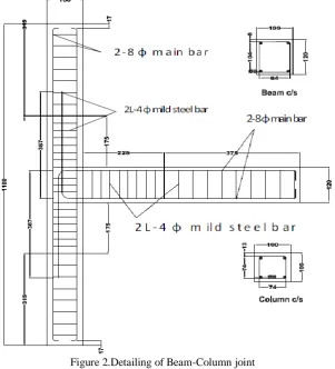
Three one third scaled beam-column joint specimens have been considered, namely RCBC (reinforced concrete Column as control specimen), SFBC (steel fibre Column), PFBC (polypropylene fibre Beam-Column) . All specimens have been designed following the provisions of ductile detailing as per IS: 13920. The
c/c. In the beam, shear reinforcement of 2 legged 4mm diameter mild steel bar with a spacing of 25mm c/c was
Figure 2.Detailing of Beam-Column joint
used near the beam column joint for a length of 225 mm and2 legged 4 mm diameter with mild steel bar a spacing of 40 mm c/c was provided for the remaining part of the beam. The detailing of specimen is shown in Figure.2 and details of three specimens are shown in Table 1.
Table 1. Detailing of all specimens
Specimen Beam Column Effective Span (mm) Cross Section (mmxmm) Longitudinal Reinforcemen t % of Steel % of Fibre Effective Span (mm) Cross Section (mmxm m) Longitu dinal Reinforc ement % of Steel % of Fibre
RCBC 500 100x120 2-8φ top
2-8φ bottom
0.97 --- 1100 100x100 4-8φ
total
1.21 ---
SFBC 500 100x120 2-8φ top
2-8φ bottom
0.97 1 1100 100x100 4-8φ
total
1.21 1
PFBC 500 100x120 2-8φ top
2-8φ bottom
0.97 1 1100 100x100 4-8φ
total
1.21 1
IV. INSTRUMENTATION AND LOADING ARRANGEMENT
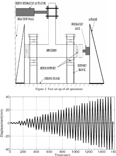
The typical schematic diagram of test set-up is shown in Figure 3. An MTS actuator of 100 kN capacity with two
A frame was used for testing of specimens. The column was placed in horizontal position while the beam was placed in vertical position in the set-up. An axial load of 10% of gross capacity of column was applied to the column to represent gravity load. The load on column was applied by a 100 kN capacity jack, which was properly calibrated. To simulate support condition at both ends of the column, roller supports were used. The actuator is of double ended and double stroke nature. The actuator of capacity ± 100 kN (Model 244.22) was used for all specimens. The double amplitude displacement is 250 mm and single amplitude it is ± 125m.
V. TESTING OF SPECIMEN
displacement histories applied to all specimens are shown in Figure 4. Three cycles of specific amplitude consisting of a push and a pull segment were repeated before the next increment in displacement was made. The first amplitude applied to all the specimens was ± 0.47mm. The next amplitude applied was followed by ± 0.47mm, ±3.3mm, ±6.6mm, ±10.3mm, ±13.6mm, ±16.6mm upto ±40.0mm. The displacement amplitude increment was 3.3 mm. The experiment was stopped for all specimens ±40.0mm in order to maintain similarity among the specimen.
Figure 3. Test set-up of all specimens
Figure 4. Typical displacement history applied for the Specimens
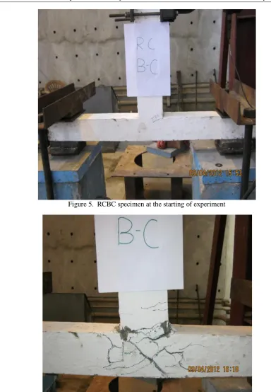
Testing of Specimen RCBC
Figure 5. RCBC specimen at the starting of experiment
Figure 6. Cracks on RCBC joint specimen at theend of testing
Figure 7. Hysteretic response of RCBC specimen
The ultimate load carrying capacity of this specimen was considered as average of peak load in pull and push direction. It was 9.5kN for the specimen RCBC.
Testing of Specimen SFBC
The testing arrangement of this specimen is shown in Figure 8. The first crack was appeared at ±3.3mm much closed to the Beam-Column joint junction.
Figure 8. SFBC specimen at the starting of experiment
Figure 9. Cracks on SFBC joint specimen at the end of testing
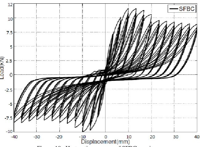
Figure 10. Hysteretic response of SFBC specimen
The maximum load carrying capacity of this specimen at push direction was 11.7kN at 12th cycle at a displacement a 10.3mm. And minimum load carrying capacity at pull direction was 10.6kN at 12th cycle at a displacement 10.3mm. Number of cracks developed on the Beam-Column joint and column surface was very less. One major crack was developed at junction and other was micro cracks. Sometime these micro cracks were difficult to observe. In Figure 9 is shown close view of Beam-Column joint at end of testing. Ultimate load carrying capacity was found 11.15kN for this specimen. The percentage of load at the end of testing came down to 81.58% and 87.8% of ultimate load in push and pull direction respectively. In Figure 10 is shown Hysteretic loop of SFBC Specimen.
Testing of Specimen PFBC
Figure 11. PFBC specimen at the starting of experiment
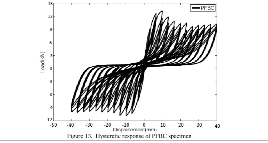
Figure 12. Cracks on PFBC joint specimen at the end of testing
Only three major cracks were appeared on the surface and others were micro cracks. These micro cracks were difficult to observe. The width of three major cracks was increased while displacement amplitude increased gradually. There were no more cracks developed on this joint. In Figure 12 is shown close view of cracks on Beam-Column joint junction after experiment. On the bottom face of the column appeared three more major crack and others were micro cracks. There was no spalling concrete condition on this specimen. The ultimate load capacity of this specimen was 10.35kN. The percentage of load at the end of testing came down to 81.9% and 94% of ultimate load in push and pull direction respectively.
VI. COMPARISON OF TEST RESULTS
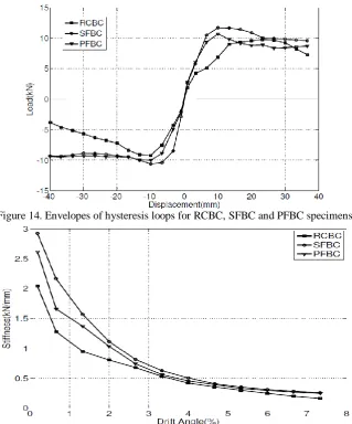
The hysteresis loops presented in Figure 7, Figure 10 and 13 shows that the load is the highest in its first cycle out of three cycles for particular displacement amplitude. Therefore, peak values of the load corresponding to first cycle for each of the displacement amplitude were used to plot envelope curve. The envelope curve of hysteresis loop RCBC, SFBC and PFBC is shown in Figure 14. It can be observed that the envelope curve for SFBC and PFBC specimens shows improvement in ultimate load carrying capacity in the push and pull direction. The improvement percentages of ultimate load carrying capacity are 17.37% and 8.95% for SFBC and PFBC specimen respectively. The envelope curves reflect nonlinear behaviour of the tested beam-column joints. The secant stiffness corresponding to a specified displacement was considered as stiffness of the assemblage. Drift angle is defined as the ratio of beam tip displacement to the length of the beam.
Figure 14. Envelopes of hysteresis loops for RCBC, SFBC and PFBC specimens
Figure 15. Stiffness versus drift angle plot for RCBC, SFBC and PFBC specimens
cumulative energy dissipated at particular amplitude was calculated by summing up the energy dissipated in all the preceding cycles including that amplitude. The plot of energy dissipation versus drift angle for RCBC, SFBC and PFBC specimens are shown in Figure 16.
Figure 16. Cumulative energy dissipated by RCBC, SFBC and PFBC specimens
Figure 17. Ductility improvement of SFBC & PFBC over RCBC
The figure shows that cumulative energy dissipated by SFBC and PFBC specimens are higher than that of RCBC specimen at every drift angle. The gains in cumulative energy dissipation at failure stage due to due to fibres (SFBC, PFBC) are 35.835% and 12.62% respectively. The displacement ductility was calculated from respective envelope curve. It may be defined as the ratio of maximum displacement to the yield displacement. In Figure 17 is shown displacement ductility of the specimens. The ductility of RCBC, SFBC and PFBC are 3.56, 7.1 and 7.3 respectively. The ductility of SFBC and PFBC specimen are higher than the RCBC specimen. Further it can be observed that the ductility increased 99.4% and 105% respectively.
VII. CONCLUSION
In the experimental study of beam-column joint a trial was made to improve this joint area providing some fibres material. Three scale model of beam-column joint was considered. The first specimen which was made of RC was treated as control specimen. Second specimen was cast by adding 1% of polypropylene fibre and similarly third specimen was cast by adding 1% of steel fibre. All specimens tested under cyclic loading to make a comparative study. The result were comparison in various plot like envelope curve, stiffness, energy dissipate and ductility.
Based on the interpretation of result the following major conclusion are drawn.-column joints, the following conclusions were drawn.
The addition of fibres plays an important role for arresting, delaying and propagating of cracks.
There was remarkable increase in load carrying capacity due to addition of fibre (ranging from 8.95% to 17.37%)
The initial stiffness for fibres specimen increased tremendously (ranging from 27.9% to 43.2%).
The energy dissipation increased considerably for fibres specimens (ranging 12.62% to 35.83%).
REFERENCES
[1]. Hanson NW, Connor HW (1967). Seismic resistance of reinforced concrete beam-column Joints.
Journal of Structural Division, 93, 533-560.
[2]. Megget LM, Park R (1971). Reinforced Concrete Exterior Beam-Column Joints Under Seismic Loading. New Zealand Engineering, 26(11), 341-353.
[3]. Scribner CF, Wight JK (1980). Strength decay in R/C beams under load Reversals. Journal of structural Division, Proceedings of the American Society of Civil Engineers, 106(ST4), 861-876.
[4]. Durrani AJ, Wight JK (1985). Behaviour of interior beam-to-column connections under earthquake-type loading. ACI Journal proceedings, 82(3), 343-349.
[5]. Abdel-Fattah B, Wight JK (1987). Study of Moving Beam Plastic Hinging Zones for Earthquake-Resistant Design of R/C Buildings. ACI Structural Journal, 31-39.
[6]. Ehsani MR, Alameddine F (1991). Design Recommendations for Type 2 High- Strength Reinforced
Concrete Connections. ACI Structural Journal, 277-291.
[7]. Murty CVR, Rai DC, Bajpai KK, Jain SK (2003). Effectiveness of reinforcement details in exterior
reinforced concrete beam-column joints for earthquake resistance. ACI structural journal, 100 (2), 149-156.
[8]. A.M. Choudhury, A. Dutta, S.K. Deb (2010). Comparative Study of Full Scaled Beam-Column Joints
Under Cyclic Loading. International Earthquake Symposium, Bangladesh Dhaka 2010.
[9]. M L Gambhir, “ Concrete Technology Theory and Practice”, Mc Graw Hill.
[10]. IS 13920 (1993). Ductile Detailing of Reinforced Concrete Structures subjected to Seismic Forces- Code of Practice. Bureau of Indian Standard, New Delhi.
[11]. C.D. Johnston, “Steel fiber reinforced mortar and concrete”, A review of mechanical properties. In
fiber reinforced concrete ACI – SP 44 – Detroit 1974
[12]. N. Ganesan, P.V. Indira and Ruby Abraham, “Steel Fibre Reinforced High Performance Concrete
Beam-Column Joints Subjected to Cyclic Loading” ISET Journal of Earthquake Technology, Technical Note, Vol. 44, No. 3-4, Sept.-Dec. 2007, pp. 445–456
[13]. ACI (1988). “Design Considerations for Steel Fiber Reinforced Concrete”, Report 544.4R-88,
American Concrete Institute, Farmington Hills, U.S.A.
[14]. Machine Hsie, Chijen Tu, P.S. Song (2008) “Mechanical properties of polypropylene hybrid
fiber-reinforced concrete” Materials Science and Engineering A 494 (2008) 153–157
[15]. Rana A. Mtasher, Dr. Abdulnasser M. Abbas & Najaat H. Ne'ma(2011) “ Strength Prediction of