Earthquake Analysis of RC Building using Clay
Infill with Regular and Irregular Geometry
Darshit Jain Saleem Akhtar
Department of Civil Engineering Department of Civil Engineering
UIT (RGPV), Bhopal (MP) UIT (RGPV), Bhopal (MP)
Aslam Hussain
Department of Civil Engineering UIT (RGPV), Bhopal (MP)
Abstract
Reinforced concrete frame buildings have become common form of construction with masonry infills in urban and semi urban areas in the world. The term infilled frame denotes a composite structure formed by the combination of a moment resisting plane frame and infill walls. The infill masonry may be of brick, concrete blocks, or stones. In the current practice of structural design in India infill walls are considered as non-structural elements and their strength and stiffness contribution are neglected. The effect of infill panels on the response of reinforced concrete frames subjected to seismic action is widely recognized and has been subject of numerous experimental and analytical investigations over last five decades. The framed building behaves differently as compared to a bare framed building (without any infill) or a fully infilled framed building under lateral load. A bare frame is much less stiff than a fully infilled frame; it resists the applied lateral load through frame action and shows well-distributed plastic hinges at failure. In this study high rise buildings of regular and irregular geometry with 200 mm clay infill thickness under earthquake Zones-V with different infill positions are considered so as to evaluate the efficient building frame. These are achieved by comparing the result with different parameter like moment, shear force, peak displacement and drift.
Keywords: Infill structure, seismic zones, framed structure, moment, forces, drift, displacements, etc.
________________________________________________________________________________________________________
I.
INTRODUCTION
In present time the reinforced concrete frame is filled with bricks as non-structural wall for partition of rooms because of its advantages such as durability, thermal insulation, cost and simple construction technique. The most likely reason of neglecting the influence of infill walls is due to their complicated failure mode. While the infill walls show brittle failure, the reinforced concrete sustains lateral loads over large post yield deformation. Moreover, past research works show that there is considerable improvement in the lateral load resisting capacity by the addition of infill walls. Inclusion of stiffness and strength of infill walls in the building frames decreases the fundamental time period compared to a bare frame and consequently increases the base shear demand and the design forces in the beams and columns. This increased design forces in the beams and columns of the buildings are not captured in the conventional bare frame analysis. An appropriate way to analyse the buildings is to model the strength and stiffness of infill walls. Unfortunately, no guidelines are given in IS 1893: 2002 (Part-1) for modelling the infill walls. As an alternative, a bare frame analysis is generally used that ignores the strength and stiffness of the infill walls. Different types of analytical models based on the physical understanding of the overall behaviour of an infill panels were developed over the years to simulate the behaviour of in filled frames. The elastic analysis based (Smith and Carter, 1969), the plastic analysis based (Liauw and Kwan, 1983), and the ultimate load based (Saneinejad and Hobbs, 1995) approaches are among them.
The presence of infill walls in buildings accounts for the following issues: 1) Increases the lateral stiffness of the building frame.
2) Decreases the natural period of vibration. 3) Increases the base shear.
4) Increases the shear forces and bending moments in the columns.
were reported to have shown the ductile behaviour but the extent of ductility is not specific. However, he concluded that the infill wall improves the strength, stiffness and energy absorption capacity of the plane structures which are useful for structures in seismic regions. Dominguez (2000) studied the effects of non-structural component on the fundamental period of buildings. The model consists of five storeys, ten storeys and fifteen storeys with diagonal struts as the infill (non-structural component). It was reported that the presence of infill decreases the fundamental period of the structure. The trend of decrease in period with increase in thickness is decreasing with the increase in height. Doudoumis (2006) studied the importance of contact condition between the infill and frame members on a single storey finite element model. He reported that the interface condition, friction coefficient, size of mesh, relative stiffness of beam to column, relative size of infill wall have significant influence on the response of infilled frame, while the effect of orthotropy of infill material was reported to be insignificant. That means that the infill can be treated as homogeneous material. When the mesh density was made finer the stress pattern within the infill was also improved, with the maximum values of stresses at the compressive corners. The existence of friction coefficient at the interface was reported to increase the lateral stiffness of the system. However, friction coefficient is dependent on the quality of material and workmanship, which is difficult to define accurately. The response parameters were also increased with the stiffness of frame and infill and the relative size of frame and infill plane. However, this study was conducted for a single storey model under monotonic loading, therefore it is important to conduct similar studies for more number of stories under earthquake load. Asokan (2006) studied how the presence of masonry infill walls in the frames of a building changes the lateral stiffness and strength of the structure. This research proposed a plastic hinge model for infill wall to be used in nonlinear performance based analysis of a building and concludes that the ultimate load (UL) approach along with the proposed hinge property provides a better estimate of the inelastic drift of the building. J. Dorji and D.P. Thambiratnam (2009) concluded that the strength of infill in terms of its Young’s Modulus (E) has a significant influence on the global performance of the structure. The stresses in the infill wall decrease with increase in (E) values due to increase in stiffness of the model. The stresses varies with building heights for a given E and seismic hazard.
II.
METHODOLOGY
Significant analytical and experimental research is carried out since five decades, which attempts to understand the behaviour of reinforced concrete frames with infill walls under earthquake loading. Various types of analytical models based on the physical understanding of the overall behaviour of an infill frame were developed over the years to simulate the behaviour of infilled frames.
In this study, the effect of clay brick masonry infill wall on a reinforced concrete moment resisting frame under earthquake loading is considered to determine the strength, stability and stiffness of building by varying infill arrangements like without, inner, outer and full infill. Comparison is done with the help of various parameter like bending moment, maximum displacement and storey displacement.
III.
GEOMETRY
For present study 09 storey buildings are considered. The buildings are considered to have regular and irregular geometry. Storey height is taken as 3 m each in all the floors and depth of foundation as 2 m. The building is kept symmetric in both orthogonal directions in plan to avoid torsional response under lateral force. The column is kept square and size of the column is kept same throughout the height of the structure to keep the discussion focussed only on the infill and partially infill effect without getting distracted by the issues like orientation of column.
IV.
MODELLING
The building is considered to be located in seismic zone V intended for residential use. The building is observed on medium strength soil through isolated footing under the columns. Response reduction factor for the special moment resisting frame has taken as 5.0 (assuming ductile detailing). The floor finish on the floors is taken to be 1.0 kN/m2. The live load on floor is been taken as 3.0 kN/m2. In seismic weight calculations, 25 % of the floor live loads are considered in the analysis.
Table – 1 Details of Structure
Type of structure Residential building (G+8)
Total height of building 27 m
Height of each storey 3 m
Depth of foundation 2 m
Bay width in longitudinal direction 3 m
Bay width in transverse direction 3 m
Size of beams 230 mm X 450 mm
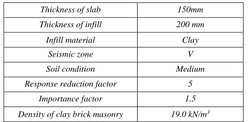
Thickness of slab 150mm
Thickness of infill 200 mm
Infill material Clay
Seismic zone V
Soil condition Medium
Response reduction factor 5
Importance factor 1.5
Density of clay brick masonry 19.0 kN/m3
V.
MODEL CONSIDERED FOR ANALYSIS
The following are the models used for the analysis of work.
Fig. 1: Plan and elevation of the bare frame structure
Fig. 2: 3D view of the bare infill wall frame at without, full, inner and outer respectively
Fig. 4: 3D view of the irregular stepped frame at without, full, inner and outer respectively
VI.
RESULTS
Results for displacements, bending moment, shear force and storey displacement are given below. Results can be described under following heads.
Maximum Displacement
Maximum displacement has been found out with infill of clay brick whose details are given below Maximum displacement in Clay Brick Infill
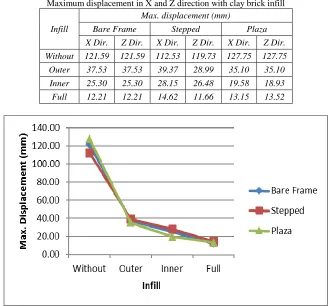
Maximum displacement of clay brick infill in X and Z direction are shown below. Table – 2
Maximum displacement in X and Z direction with clay brick infill
Infill
Max. displacement (mm)
Bare Frame Stepped Plaza
X Dir. Z Dir. X Dir. Z Dir. X Dir. Z Dir.
Without 121.59 121.59 112.53 119.73 127.75 127.75 Outer 37.53 37.53 39.37 28.99 35.10 35.10
Inner 25.30 25.30 28.15 26.48 19.58 18.93 Full 12.21 12.21 14.62 11.66 13.15 13.52
Fig. 5: Maximum displacement in Z direction with clay brick infill
Maximum displacement is observed in without infill plaza structure and minimum in full infill stepped structure in Z direction Storey Displacement
Storey displacement has been found out with infill of clay brick whose details are given below Storey Displacement in Clay Brick Infill
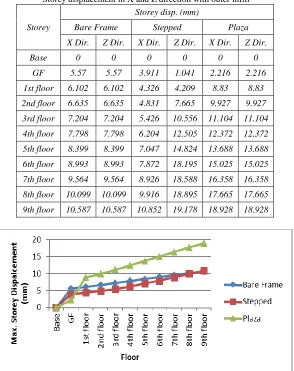
Storey displacement of clay brick infill X and Z direction are shown in below. Table – 3
Storey displacement in X and Z direction with outer infill
Storey
Storey disp. (mm)
Bare Frame Stepped Plaza
X Dir. Z Dir. X Dir. Z Dir. X Dir. Z Dir.
Base 0 0 0 0 0 0
GF 5.57 5.57 3.911 1.041 2.216 2.216
1st floor 6.102 6.102 4.326 4.209 8.83 8.83
2nd floor 6.635 6.635 4.831 7.665 9.927 9.927
3rd floor 7.204 7.204 5.426 10.556 11.104 11.104
4th floor 7.798 7.798 6.204 12.505 12.372 12.372
5th floor 8.399 8.399 7.047 14.824 13.688 13.688
6th floor 8.993 8.993 7.872 18.195 15.025 15.025
7th floor 9.564 9.564 8.926 18.588 16.358 16.358
8th floor 10.099 10.099 9.916 18.895 17.665 17.665
9th floor 10.587 10.587 10.852 19.178 18.928 18.928
Fig. 7: Storey displacement with outer infill clay brick in Z direction
Maximum storey displacement with outer infill is maximum in stepped structure and minimum is in bare frame. Table – 4
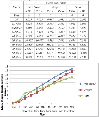
Storey displacement in X and Z direction with inner infill
Storey
Storey disp. (mm)
Bare Frame Stepped Plaza
X Dir. Z Dir. X Dir. Z Dir. X Dir. Z Dir.
Base 0 0 0 0 0 0
GF 1.025 1.025 0.637 2.982 1.594 2.302
1st floor 3.476 3.476 2.337 3.831 4.961 3.004 2nd floor 5.503 5.503 3.823 4.593 5.743 3.943
3rd floor 7.319 7.319 5.166 5.473 6.637 5.018 4th floor 9.085 9.085 6.781 6.423 7.624 6.174
5th floor 10.857 10.857 8.513 7.432 8.674 7.383 6th floor 12.626 12.626 10.227 8.491 9.761 8.622
7th floor 14.324 14.324 12.264 9.578 10.865 9.869
8th floor 15.813 15.813 14.173 10.665 11.966 11.105 9th floor 16.85 16.85 15.53 11.689 13.051 12.32
Fig. 9: Storey displacement with inner infill clay brick in Z direction
Maximum storey displacement with inner infill is maximum in bare frame and minimum is in stepped structure. Table – 5
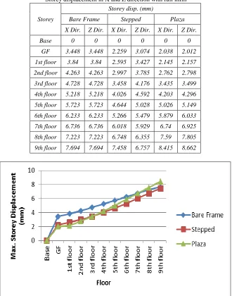
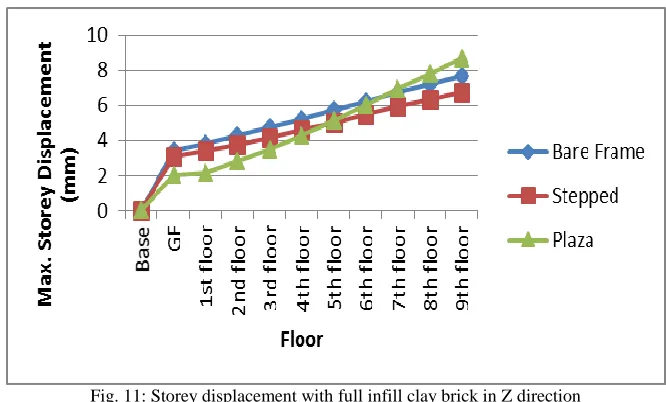
Storey displacement in X and Z direction with full infill
Storey
Storey disp. (mm)
Bare Frame Stepped Plaza
X Dir. Z Dir. X Dir. Z Dir. X Dir. Z Dir.
Base 0 0 0 0 0 0
GF 3.448 3.448 2.259 3.074 2.038 2.012
1st floor 3.84 3.84 2.595 3.427 2.145 2.157
2nd floor 4.263 4.263 2.997 3.785 2.762 2.798
3rd floor 4.728 4.728 3.458 4.176 3.435 3.499
4th floor 5.218 5.218 4.026 4.592 4.203 4.296
5th floor 5.723 5.723 4.644 5.028 5.026 5.149
6th floor 6.233 6.233 5.266 5.479 5.879 6.033
7th floor 6.736 6.736 6.018 5.929 6.74 6.925
8th floor 7.223 7.223 6.748 6.355 7.59 7.805
9th floor 7.694 7.694 7.458 6.757 8.415 8.662
Fig. 11: Storey displacement with full infill clay brick in Z direction
Maximum storey displacement with outer infill is maximum in plaza structure and minimum is in stepped structure. Bending Moment
Maximum bending moment of clay brick infill are shown below. Table – 6
Maximum bending moment with clay brick infill
Maximum bending moment (kNm) in clay brick
Infill Bare Frame Stepped Plaza
Without 204.259 211.988 223.859
Outer 92.797 116.838 183.555
Inner 120.244 108.53 121.41
Full 39.155 82.536 55.782
Fig. 12: Maximum bending moment with clay brick infill
Shear Force
Maximum sheer force of clay brick infill is below.
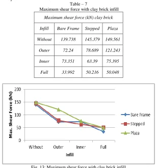
Table – 7
Maximum shear force with clay brick infill
Maximum shear force (kN) clay brick
Infill Bare Frame Stepped Plaza
Without 139.738 145.379 149.561
Outer 72.24 78.689 121.243
Inner 73.351 63.39 75.395
Full 33.992 50.216 50.048
Fig. 13: Maximum shear force with clay brick infill
Maximum shear force is in without infill plaza and minimum is in full bare frame
VII.
CONCLUSION
The value of maximum displacement, storey displacement, maximum bending moment and maximum shear force is observed highest in without infill structure and it is comparatively less in case of inner infill structure, still less in outer infill structure and lowest in full infill structure.
It can be concluded from the study that the value of various distractive parameter namely maximum displacement, storey displacement, maximum bending moment and maximum shear force Full infill is best and efficient pattern because these parameters are lowest in this case further based on same line we can conclude that inner infill and outer infill is second best and third best respectively whereas without infill structure can be termed as critical structure.
If we consider irregular structure than plaza structure is more effective compared to other structure because plaza structure shows lower parameters
Although the dead weight of the structure increases with infill but it increases the stiffness of the structure which is an important factor in seismic design of structures
REFERENCES
[1] Al-Chaar G., Issa M. and Sweeney S. 'Behaviour of masonry infilled non-ductile RC frames’, ASCE Journal of Structural Engineering. 128(8), 1055-1063.
1998
[2] Asokan A. 'Modelling of Masonry Infill Walls for Nonlinear Static Analysis under Seismic Loads', MS Thesis. Indian Institute of Technology Madras, Chennai, 2006
[3] Dukuze A, 'Behaviour of reinforced concrete frames infilled with brick masonry panels', Canada, University of New Brunswick (Canada), 2000
[4] Dominguez Morales M. (2000). Fundamental period of vibration for reinforced concrete buildings. Canada, University of Ottawa (Canada).
[5] Doudoumis I.N. (2006). Finite element modelling and investigation of the behaviour of elastic infilled frames under monotonic loading. Engineering Structures. 29(6),1004-1024.
[6] Fardis M.N. and Panagiotakos T. B. 'Seismic design and response of bare and masonry-infilled concrete buildings', Journal of Earthquake Engineering. 1,
[7] Kanitkar R. and Kanitkar V. (2004). Seismic performance of conventional multi-storey buildings with open ground storey floors for vehicular parking. The Indian Concrete Journal. 78, 99-104.
[8] Sattar S. and Abbie B. L. (2010). Seismic Performance of Reinforced Concrete Frame Structures with and without Masonry Infill Walls, 9th U.S. National
and 10th Canadian Conference on Earthquake Engineering, Toronto, Canada.
[9] Scarlet A. (1997). Design of Soft Stories – A simplified energy approach. Earthquake Spectra. 13, 305-315.
[10] Smith S. B. (1962). Lateral Stiffness of Infilled Frames. ASCE Journal of the Structural Division. 88, 183-199.
[11] S. B. Smith and Carter C. (1969). A Method of Analysis for Infilled Frames. Proceedings of Institution of Civil Engineers. 44, 31-48.
[12] Subramanian N. (2004). Discussion on seismic performance of conventional multi-storey building with open ground floors for vehicular parking by Kanitkar
and Kanitkar. The Indian Concrete Journal. 78, 11-13.
[13] User's manual, STAAD.Pro software (2013)
[14] W Khan, S Akhtar, A Hussain, Non Linear time History Analysis of Tall Structure for Seismic Load using Damper, International Journal Of Scientific And
Research Publication, Vol 4, Issue 4, (2014).
[15] U Arya, A Hussain, W Khan, Wind Analysis of Building Frames on sloping ground, International Journal of Scientific And Research Publication, Vol 4,
Issue 5, (2014).
[16] ST Hussain, A Hussain, Vibration Analysis of Composite Beam with Cracks, International Journal of Engineering Associates, Vol 4, Issue 9, (2015).
[17] J Chajlani, A Hussain, Application of FRP in Concerte Structures, International Journal of Engineering associates, Vol 4 , Issue 8, (2015)
[18] S T Hussain, A Hussain, Numerical Analysis of composite beam by using Ansys – A Review, International Journal of Engineering Associates, Vol 4, Issue
9 , (2015)
[19] J Chajlani, A Hussain, Analysis of repairs and rehabilitation of RCC Structures, International Journal of Engineering Associates, Vol 4 Issue 8, (2015)
[20] IH Khan, R patel, A Hussain, “Parametric Analysis of hyperbolic cooling tower under seismic loads through Staad.Pro” International Research Journal of
Engineering and technology, Volume 2, Issue 9, (2015)
[21] Darshit jain , Saleem Akhtar , Aslam Hussain , “Earthquake Analysis of RC building using cement infill with Regular and Irregular Geometry” International