ISSN (e): 2250-3021, ISSN (p): 2278-8719
Vol. 08, Issue 9 (September. 2018), ||V (III) || PP 53-61
Bending Analysis of Rectangular Thick Plate Using Polynomial
Shear Deformation Theory
1
Ibearugbulem, Owus M.,
2Ezeh, John C.,
3Ettu, Lawrence O.,
4
Gwarah, Ledum S.
1,2,3,4
Civil Engineering Department, Federal University of Technology, Owerri, Nigeria Corresponding Author: 1Ibearugbulem
Abstract:
This paper presents bending analysis of all clamped (CCCC) rectangular thick plate using polynomial shape function in shear deformation theory. The theory presented herein is based on Ritz energy method and the displacement function based on polynomial function. The theory derived transverse shear stress from constitutive relation that satisfied zero shear stress condition on the top and bottom surfaces of the plate, hence like other higher order theories no shear correction factor is required. The total potential energy equation of a thick plate was formulated from the principle elasticity. The governing equations for determination of displacement coefficients were derived by subjecting the total potential energy equation to direct variation. A rectangular thick plate with all edges clamped was considered for numerical studies. The results obtained herein for displacements and stresses were compares with those from previous works to show the sufficiency of this theory. It was observed that the present results agreed with those of previous works. Also the obtained non-dimensional values of vertical shear stress (𝝉 𝒙𝒛) were used to delineate the boundary between thick and thin plate based on span to depth ratio. The values of non-dimensional vertical shear stress (𝝉 𝒙𝒛) between span to depth ratios (α) of 60 and 100 were equal to values obtained from classical plate theory (CPT), therefore they can be idealized to be thin plate. The values of the vertical shear stress (𝝉 𝒙𝒛) of plate, whose span to depth ratio (α) falls between 20 and 50 varied minimally and differed from those of classical plate theory, so the plate can be taken to be moderately thick. Furthermore, values of the vertical shear stress (𝝉 𝒙𝒛) of plate whose span to depth ratio (α) falls between 4 to 15 varied significantly with span to depth ratio. Therefore, the plate can be taken to be thick..Keywords
: shear deformation, shear correction factor, vertical shear stress, deflection, displacement, potential energy--- --- Date of Submission: 08-09-2018 Date of acceptance: 24-09-2018 --- ---
I.
INTRODUCTION
at both the top and bottom surfaces (Kruszewski, 1949; Ambartsumian, 1958 Krishna, 1984; Touratier, 1991; Karama and Mistou, 2003; Sayyad, 2011). They came up with different shear deformation line functions, here-in-after called F(z). However, their F(z) are not strictly based on the vertical shear stress mathematical formulation. As discussed earlier, scholars had been assuming displacement functions in thick plate bending analysis. The correctness of the analysis through variational or energy approaches depend more on the exactness of the assume displacement function. This seems to be the major factor discouring engineers in petronizing thick plate analysis, and instead resort to idealizing thick plate as thin plates. In this paper, the authors tried to integrate the thick plate governing equation to obtain general polynomial displacement function, which was easy to satisfy the boundary condintion for various plates. They also, tried to propagate an easy and straightforwad approach to bending analysis of thick rectangular plates..
II.
TEORITICAL FORMULATION
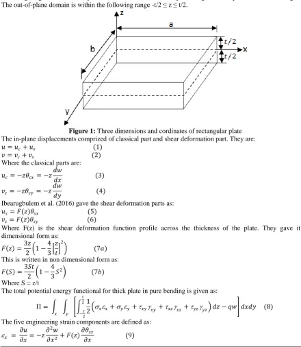
The displacement field include two in-plane displacements (u and v) and out-of-plane displacement (w). While the inplane displacements are differentiable with respect to the three cardinal coordinates, the out-of-plane displacement is only differentiable with respect to x and y coordinates. The in-out-of-plane domains are in the following range: 0 ≤ x ≤ a;0 ≤ y ≤ b. Where a and b are the in-plane lengths of the plate as shown on Figure 1. The out-of-plane domain is within the following range -t/2 ≤ z ≤ t/2.
Figure 1: Three dimensions and cordinates of rectangular plate The in-plane displacements comprized of classical part and shear deformation part. They are: 𝑢 = 𝑢𝑐+ 𝑢𝑠 (1)
𝑣 = 𝑣𝑐+ 𝑣𝑠 (2) Where the classical parts are:
𝑢𝑐= −𝑧𝜃𝑐𝑥 = −𝑧 𝑑𝑤
𝑑𝑥 (3)
𝑣𝑐 = −𝑧𝜃𝑐𝑦 = −𝑧 𝑑𝑤
𝑑𝑦 (4)
Ibearugbulem et al. (2016) gave the shear deformation parts as: 𝑢𝑠= 𝐹(𝑧)𝜃𝑠𝑥 (5)
𝑣𝑠= 𝐹(𝑧)𝜃𝑠𝑦 (6)
Where F(z) is the shear deformation function profile across the thickness of the plate. They gave it in dimensional form as:
𝐹 𝑧 =3𝑧 2 1 −
4 3
𝑧 𝑡
2
(7𝑎)
This is written in non dimensional form as:
𝐹 𝑆 =3𝑆𝑡 2 1 −
4 3𝑆
2 (7𝑏)
Where S = z/t
The total potential energy functional for thick plate in pure bending is given as:
Π= 1
2 𝑥𝑥+𝑦𝑦+𝑥𝑦𝑥𝑦 +𝑥𝑧𝑥𝑧+𝑦𝑧𝑦𝑧 𝑑𝑧 𝑡
2
−2𝑡
− 𝑞𝑤 𝑦
𝑥
𝑑𝑥𝑑𝑦 (8)
The five engineering strain components are defined as:
𝑥 = 𝜕𝑢 𝜕𝑥= −𝑧
𝜕2𝑤 𝜕𝑥2 + 𝐹(𝑧)
𝜕𝜃𝑠𝑥
𝑦 = 𝜕𝑣 𝜕𝑦= −𝑧
𝜕2𝑤 𝜕𝑦2 + 𝐹(𝑧)
𝜕𝜃𝑠𝑦
𝜕𝑦 (10)
𝑥𝑦 = 𝑑𝑢 𝑑𝑦+
𝑑𝑣
𝑑𝑥. 𝑇𝑎𝑡 𝑖𝑠:
𝑥𝑦 = −2𝜕
2𝑤
𝜕𝑥𝜕𝑦+ 𝐹 𝑧 𝜕𝜃𝑠𝑥
𝜕𝑦 + 𝐹 𝑧 𝜕𝜃𝑠𝑦
𝜕𝑥 (11)
𝑥𝑧 = 𝑑𝑢 𝑑𝑧+
𝑑𝑤
𝑑𝑥. 𝑇𝑎𝑡 𝑖𝑠:
𝑥𝑧 =𝜕𝐹 𝑧
𝜕𝑧 . 𝜃𝑠𝑥 (12)
𝑦𝑧 =𝜕𝐹 𝑧
𝜕𝑧 . 𝜃𝑠𝑦 (13) The corresponding five stress components are:
𝑥 = 𝐸
1 −2 𝑥+ 𝑦 (14)
𝑦 = 𝐸
1 −2 𝑥+ 𝑦 (15)
𝑥𝑦 =
𝐸(1 −)
1 −2 𝑥𝑦 (16)
𝑥𝑧 =
𝐸(1 −)
1 −2 𝑥𝑧 (17)
𝑦𝑧 =
𝐸(1 −)
1 −2 𝑦𝑧 (18) Substituting equations (14) to (18) into equation (8) gave:
Π= 𝐸
2 1 − 𝜇2 𝜀𝑥𝑥2 + 2𝜇𝜀𝑥𝑥. 𝜀𝑦𝑦 + 𝜀𝑦𝑦2 + 1 − 𝜇 𝛾𝑥𝑦2
2 + 𝛾𝑥𝑧2
2 + 𝛾𝑦𝑧2
2 𝑑𝑧 𝑡 2 −𝑡 2 − 𝑞𝑤 𝑦 𝑥
𝑑𝑥𝑑𝑦 (19)
Substituting equations (9) to (13) into equation (19) gave:
Π=𝐷
2 { 𝑑2𝑤
𝑑𝑥2 2
+ 2 𝑑 2𝑤 𝑑𝑥𝑑𝑦 2 + 𝑑 2𝑤 𝑑𝑦2 2
− 2𝑔2 𝑑2𝑤 𝑑𝑥2
dθsx dx +
𝑑2𝑤 𝑑𝑥2.
dθsy dy +
𝑑2𝑤 𝑑𝑦2.
dθsx dx +
𝑑2𝑤 𝑑𝑦2
dθsy dy
+𝑔3 dθsx
dx 2
+ 1 + 𝜇 dθsx dx
dθsy dy +
dθsy dy
2
+ 1 − 𝜇 2
dθsx dy
2 + dθsy
dx 2
+ 1 − 𝜇 2 𝑔4 θsx
2+θ sy2
−2𝑞𝑤
𝐷 } 𝑑𝑥 𝑑𝑦 (20)
Where:
D = Et 3
12 1 −2 ; g2 = 12
t3 𝑧F z dz t
2
−2t
= 1.2
g3= 12
t3 F z 2 dz t
2
−t 2
=51
35; g4=∝ 2g
5
g5= 12
t3 dF(z)
dz 2
dz = 14.4 t
2
−t2
Writing eequation (20) in terms of the non-dimensional coordinates gave:
Π=𝑎𝑏𝐷 2 {
1 𝑎4 1 0 1 0 𝑑 2𝑤 𝑑𝑅2 2 + 2 𝛽2
𝑑2𝑤 𝑑𝑅𝑑𝑄 2 + 𝑑 2𝑤 𝑑𝑄2 2
−2𝑔2 𝑎3
𝑑2𝑤 𝑑𝑅2
dθsx dR +
1 𝛽
𝑑2𝑤 𝑑𝑅2.
dθsy dQ +
1 𝛽2
𝑑2𝑤 𝑑𝑄2.
dθsx dR +
1 𝛽3
𝑑2𝑤 𝑑𝑄2
dθsy dQ
+𝑔3 𝑎2
dθsx dR
2
+ 1 + 𝜇 𝛽
dθsx dR
dθsy dQ +
1 𝛽2
dθsy dQ
2
+ 1 − 𝜇 2𝛽2
dθsx dQ
2 + dθsy
dR 2
+ 1 − 𝜇 2 𝑔4 θsx
2+θ sy2 −
2𝑞𝑤
Minimizing equation (20) with respect to deflection and the shear deformation rotations (w, sx and sy) gave the
governing eqation and two compatibility equations respectively as: 𝑞
𝐷= 𝑑4𝑤 𝑑𝑥4 + 2
𝑑4𝑤 𝑑𝑥2𝑑𝑦2+
𝑑4𝑤 𝑑𝑦4 − 𝑔2
d3θ sx dx3 +
d3θ sx dxdy2+
d3θ sy 𝑑𝑥2dy+
d3θ sy
dy3 (23𝑎)
𝐷[g2 𝑑3𝑤 𝑑𝑥3 +
𝑑3𝑤 𝑑𝑥𝑑𝑦2 − g3
d2θ sx dx2 +
1 − 𝜇 2
d2θ sx dy2 − g3
1 + 𝜇 2
d2θ sy dxdy −
1 − 𝜇
2 g4θsx] = 0 (23𝑏)
𝐷[g2 𝑑3𝑤 𝑑𝑦3 +
𝑑3𝑤 𝑑𝑥2𝑑𝑦 − g3
d2θ sy dy2 +
1 − 𝜇 2
d2θ sy dx2 − g3
1 + 𝜇 2
d2θ sx dxdy −
1 − 𝜇
2 g4θsy] = 0 (23c)
III.
SOLUTIONS OF GOVERNING EQUATIONS
Solving equations (23b) and (23c) simultabeously gave:
θsx = g2 g3
𝑑𝑤 𝑑𝑥 =
2g2 g3 1 − 𝜇
𝑑𝑤 𝑑𝑥 = 𝑐
𝑑𝑤
𝑑𝑥 (24)
θsy = g2 g3
𝑑𝑤 𝑑𝑦 =
2g2 g3 1 − 𝜇
𝑑𝑤 𝑑𝑦 = 𝑐
𝑑𝑤
𝑑𝑦 (25) d2
dxdy= −
1 − 𝜇 g4 1 + 𝜇 g3
(26)
Where, c is a yet to be determined constant.
Substituting equations (24), (25) and (26) into equation 23a and rearranging gave: 𝑑4𝑤
𝑑𝑥4 + 2 𝑑4𝑤 𝑑𝑥2𝑑𝑦2+
𝑑4𝑤 𝑑𝑦4 =
𝑃𝑃 𝐷 1 − 𝑔2𝑐
(27)
The ready solution to equation (27) after integration in terms of non dimensional coordinates is: w = h A1= hx ax . hy ay (28)
where:
ax T= a0a1a2a3a4 ; ay
T
= b0b1b2b3b4
hx = 1 R R2R3R4 ; hy = 1 Q Q2Q3Q4
Substituting equation (28) into equations (24) and (25) gave (in terms non dimensional coordinates):
θsx = 𝑐 𝑑𝑤
𝑑𝑥 = A2
a 𝑑
𝑑𝑅 (29) θsy = 𝑐
𝑑𝑤 𝑑𝑦 =
A3 b
𝑑
𝑑𝑄 (30) The boundary conditions for cccc plate are:
𝐴𝑡 𝑒𝑑𝑔𝑒 𝑜𝑓 𝑝𝑙𝑎𝑡𝑒; 𝑥 = 0 , 𝑎: 𝑤 =𝑑𝑤 𝑑𝑥 = 0 𝐴𝑡 𝑒𝑑𝑔𝑒 𝑜𝑓 𝑝𝑙𝑎𝑡𝑒; 𝑦 = 0 , 𝑏: 𝑤 =𝑑𝑤
𝑑𝑦 = 0 Satisfying these boubdary conditions gave: 𝑤 = 𝐴1 𝑅2− 2𝑅3+ 𝑅4 . 𝑄2− 2𝑄3+ 𝑄4
IV.
DETERMINATION OF DISPLACEMENT COEFFICIENTS
Substituting equations (28), (29) and (30) into equation (21) and minimizing the outcome with respect to A1, A2
and A3 respectively gave: 𝑞𝑎4
𝐷 . 𝑘𝑞𝐴1= 𝐴1
2− 𝑔
2𝐴1𝐴2 𝑘𝑥 + 2𝐴12− 𝑔2𝐴1𝐴2− 𝑔2𝐴1𝐴3 1
𝛽2𝑘𝑥𝑦 + 𝐴12− 𝑔2𝐴1𝐴3 1
𝛽4𝑘𝑦 (31)
g3𝑘𝑥+ g3 1 − 𝜇
2𝛽2 𝑘𝑥𝑦 + 1 − 𝜇
2 g5 a t
2
𝑘𝑁𝑥 𝐴2 + g3 1 + 𝜇
2𝛽2 𝑘𝑥𝑦𝐴3= 𝑘𝑥+ 𝑘𝑥𝑦
𝛽2 g2𝐴1 (32) 𝑔3
𝛽4𝑘𝑦+ 𝑔3 1 − 𝜇
2𝛽2 𝑘𝑥𝑦 + 1 − 𝜇
2𝛽2 g5 a t
2
𝑘𝑁𝑦 𝐴3 + 𝑔3 1 + 𝜇
2𝛽2 𝑘𝑥𝑦𝐴2= 𝑘𝑦 𝛽4+
𝑘𝑥𝑦
𝛽2 𝑔2𝐴1 (33) Where:
𝑘𝑥𝑦 = 𝑑2 𝑑𝑅 𝑑𝑄 2 1 0 1 0 𝑑𝑅 𝑑𝑄 𝑘𝑦 = 𝑑2 𝑑𝑄2 2 1 0 1 0 𝑑𝑅 𝑑𝑄 𝑘𝑁𝑥 = 𝑑 𝑑𝑅 2 1 0 1 0 𝑑𝑅 𝑑𝑄 𝑘𝑁𝑦 = dh dQ 2 1 0 1 0 𝑑𝑅 𝑑𝑄
𝑘𝑞 = h 1
0 1
0
𝑑𝑅 𝑑𝑄
Solving equations (32) and (33) simultaneously gave:
𝐴2= 𝑇2𝐴1 (34) 𝐴3= 𝑇3𝐴1 (35) Where:
𝑇2=
c12c23− c13c22 c12c12− c11c22
(36)
𝑇3=
c12c13− c11c23 c12c12− c11c22
(37)
c11= g3𝑘𝑥+ g3 1 − 𝜇
2𝛽2 𝑘𝑥𝑦 + 1 − 𝜇
2 g5 a t
2 𝑘𝑁𝑥
c12= g3 1 + 𝜇
2𝛽2 𝑘𝑥𝑦; c13= 𝑘𝑥+ 𝑘𝑥𝑦
𝛽2 g2
c22= 𝑔3
𝛽4𝑘𝑦+ 𝑔3 1 − 𝜇
2𝛽2 𝑘𝑥𝑦 + 1 − 𝜇
2𝛽2 g5 a t
2 𝑘𝑁𝑦
c23= 𝑘𝑦 𝛽4+
𝑘𝑥𝑦 𝛽2 𝑔2
Substituting equations (36) and (37) into equation (31) and reaaranging the out-come gave: 𝐴1𝐷
𝑞𝑎4 = 𝑘𝑞 𝑘𝑇
(38)
Where:
𝑘𝑇= 1 − 𝑔2𝑇2 𝑘𝑥+ 2 − 𝑔2𝑇2− 𝑔2𝑇3 1
𝛽2𝑘𝑥𝑦 + 1 − 𝑔2𝑇3 1 𝛽4𝑘𝑦
V.
DEFINITION OF PARAMETERS
The following definitions for parameters were made:
𝑤 = 𝑤 𝑞𝑎 4
𝐷 = 𝐴1 𝑞𝑎4 𝐷 𝑢 = 𝑢 𝑞𝑎 4 𝐷 = 1
∝ −𝐴1𝑆 + 𝐴2𝐹(𝑆) 𝑑 𝑑𝑅. 𝑞𝑎4 𝐷 𝑣 = 𝑣 𝑞𝑎 4 𝐷 = 1
𝑃 ∝ −𝐴1𝑆 + 𝐴3𝐹(𝑆) 𝑑 𝑑𝑄
𝑞𝑎4 𝐷
𝜎𝑥= 𝜎 . 𝑞 = 12𝑞 ∝𝑥 2 −𝐴1𝑆 + 𝐴2𝐹 𝑆 𝑑2 𝑑𝑅2+
𝑃2 −𝐴1𝑆 + 𝐴3𝐹(𝑆) 𝑑2 𝑑𝑄2
𝜎𝑦= 𝜎 . 𝑞 = 12𝑞 ∝𝑦 2 −𝐴1𝑆 + 𝐴2𝐹 𝑆 𝑑2 𝑑𝑅2+
1
𝑃2 −𝐴1𝑆 + 𝐴3𝐹(𝑆) 𝑑2 𝑑𝑄2
𝜏𝑥𝑦 = 𝜏 . 𝑞 =𝑥𝑦 6𝑞 ∝2
𝑃 −2𝐴1𝑆 + 𝐴2𝐹 𝑆 + 𝐵3𝐹(𝑆) 𝑑2
𝑑𝑅𝑑𝑄 (1 −)
𝜏𝑥𝑧 = 𝜏 . 𝑞 = 6𝑞 ∝𝑥𝑧 3 𝐴2 𝑑𝐹 𝑆
𝑑𝑆 𝑑
𝑑𝑅 (1 −)
𝜏𝑦𝑧 = 𝜏 . 𝑞 = 6𝑞 ∝𝑦𝑧 3 𝐴3
𝑃 𝑑𝐹 𝑆
𝑑𝑆 𝑑
𝑑𝑄 (1 −)
Determine the in-plane displacements (u and v) at (R = 0.5; Q = 0.5; S = 0.2) of cccc thick plate. Determine also the in-plane normal stresses x and y at (R = 0.5; Q = 0.5; S = 0.5), in-plane shear stress (xy) at (R = 0; Q = 0;
S = 0.5) and the vertical shear stress (xz) at (R = 0.2; Q = 0.5; S = 0.2) of the cccc thick plate. Polynomial
displacement function for cccc plate used in this analysis is: = 𝑅2− 2𝑅3+ 𝑅4 . 𝑄2− 2𝑄3+ 𝑄4 .
The stiffness coefficients (k values) from this displacement function are: 𝑘1= 0.00127; 𝑘2= 0.000363; 𝑘3= 0.00127
𝑘4= 0.0000302; 𝑘4= 0.0000302 Frq = 0.00111
VII.
RESULTS AND DISCUSSIONS
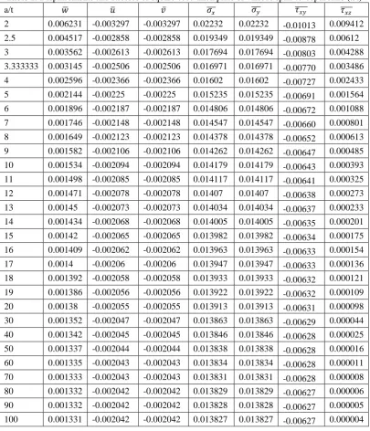
The value of vertical shear stress from classical plate theory (CPT) analysis is zero. Any plate whose span-to-depth ratio is such that the value of vertical shear stress from thick plate analysis is approximately zero can be idealized as thin plate. Analyzing such plate with classical plate theory will not introduce significant errors. From Table 1, it is apparent that for span-to-depth ratio between 60 and 100, the value of vertical shear stress is significant when corrected to 6 decimal places. Hence, for such span-to-depth ratio, the plate is classified as thin plate. For span-to-depth ratio between 20 and 50, the value of vertical shear stress is significant when corrected to 5 decimal places. Thus, these plates can be classified as moderately thick plate. Hence, analyzing them with classical plate theory will introduce significant errors. When the span-to-depth ratio is less than 20, the value of vertical shear stress is significant when corrected to 4 decimal places. This range of span-to-depth ratio produces plate classified as thick plate.
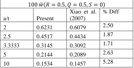
To determine the correctness of the results from the present studies, comparison was made between values from the present study and those from past scholars. These comparisons were presented on Table 2, Table 3 and Table 4. Table 2 shows the values of centroidal deflection (which was multiplied by 100) for square cccc plate at various span-to-depth ratios from the present study and those from past scholars. The percentage differences between the values from the present study and those of past scholars were presented on Table3 and Table 4. A critical look at Table 3 reveals that maximum recorded percentage difference is 4.07 % (Li et al., 2014; Sheng and He,1995; Liu and Liew, 1998; Lok and Cheng, 2001; Zhong and Xu, 2017). This implies that at 96 % confidence level, the values from the present study are the same with those of previous studies. Furthermore, it is evident from Table 4 that the maximum percentage difference between the values from the present study and those from Xiao et al. (2007) is 5.28 %. Again, at 94 % confidence level, the values from the present study are the same with those from Xiao et al. (2007).
Table 1: Displacements and stresses of square cccc thick plate of various span-to-depth ratio (a/t)
a/t 𝑤 𝑢 𝑣 𝜎 𝑥 𝜎 𝑦 𝜏 𝑥𝑦 𝜏 𝑥𝑧
2 0.006231 -0.003297 -0.003297 0.02232 0.02232 -0.01013 0.009412 2.5 0.004517 -0.002858 -0.002858 0.019349 0.019349 -0.00878 0.00612 3 0.003562 -0.002613 -0.002613 0.017694 0.017694 -0.00803 0.004288
3.333333 0.003145 -0.002506 -0.002506 0.016971 0.016971 -0.00770 0.003486 4 0.002596 -0.002366 -0.002366 0.01602 0.01602 -0.00727 0.002433 5 0.002144 -0.00225 -0.00225 0.015235 0.015235 -0.00691 0.001564 6 0.001896 -0.002187 -0.002187 0.014806 0.014806 -0.00672 0.001088
7 0.001746 -0.002148 -0.002148 0.014547 0.014547 -0.00660 0.000801 8 0.001649 -0.002123 -0.002123 0.014378 0.014378 -0.00652 0.000613 9 0.001582 -0.002106 -0.002106 0.014262 0.014262 -0.00647 0.000485 10 0.001534 -0.002094 -0.002094 0.014179 0.014179 -0.00643 0.000393
11 0.001498 -0.002085 -0.002085 0.014117 0.014117 -0.00641 0.000325 12 0.001471 -0.002078 -0.002078 0.01407 0.01407 -0.00638 0.000273 13 0.00145 -0.002073 -0.002073 0.014034 0.014034 -0.00637 0.000233 14 0.001434 -0.002068 -0.002068 0.014005 0.014005 -0.00635 0.000201
15 0.00142 -0.002065 -0.002065 0.013982 0.013982 -0.00634 0.000175 16 0.001409 -0.002062 -0.002062 0.013963 0.013963 -0.00633 0.000154 17 0.0014 -0.00206 -0.00206 0.013947 0.013947 -0.00633 0.000136 18 0.001392 -0.002058 -0.002058 0.013933 0.013933 -0.00632 0.000121
19 0.001386 -0.002056 -0.002056 0.013922 0.013922 -0.00632 0.000109 20 0.00138 -0.002055 -0.002055 0.013913 0.013913 -0.00631 0.000098 30 0.001352 -0.002047 -0.002047 0.013863 0.013863 -0.00629 0.000044 40 0.001342 -0.002045 -0.002045 0.013846 0.013846 -0.00628 0.000025
50 0.001337 -0.002044 -0.002044 0.013838 0.013838 -0.00628 0.000016 60 0.001335 -0.002043 -0.002043 0.013834 0.013834 -0.00628 0.000011 70 0.001333 -0.002043 -0.002043 0.013831 0.013831 -0.00628 0.000008 80 0.001332 -0.002042 -0.002042 0.013829 0.013829 -0.00627 0.000006
90 0.001332 -0.002042 -0.002042 0.013828 0.013828 -0.00627 0.000005 100 0.001331 -0.002042 -0.002042 0.013827 0.013827 -0.00627 0.000004
𝐿𝑒𝑔𝑒𝑛𝑑: 𝑤 = 𝑤 𝑅 = 0.5, 𝑄 = 0.5, 𝑆 = 0.5 ; 𝑢 = 𝑢 𝑅 = 0.2, 𝑄 = 0.5, 𝑆 = 0.5 𝑣 = 𝑣 𝑅 = 0.5, 𝑄 = 0.2, 𝑆 = 0.5 ; 𝜎 = 𝜎𝑥 𝑅 = 0.5, 𝑄 = 0.5, 𝑆 = 0.5 𝑥
𝜎𝑦
= 𝜎 𝑅 = 0.5, 𝑄 = 0.5, 𝑆 = 0.5 ; 𝜏𝑦 = 𝜏𝑥𝑦 𝑅 = 0.2, 𝑄 = 0.2, 𝑆 = 0.5 𝑥𝑦 𝜏𝑥𝑧
Table 2: Centroidal deflection of square cccc thick plate multiplied by hundred
100 𝑤 𝑅 = 0.5, 𝑄 = 0.5, 𝑆 = 0
Span-to-depth ratio (a/t) Present
Li et al. (2014)
Sheng and He (1995)
Liu and Liew (1998)
Lok and Cheng (2001)
Zhong and Xu (2017)
3 0.3562 * * * * 0.3611
5 0.2144 0.2172 0.2204 0.2172 0.2147 0.2114
10 0.1534 0.1505 0.1513 0.1505 0.1495 0.1483
20 0.1381 0.1327 0.1329 0.1327 * *
Table 3: Percentage difference between the values of centroidal deflection from present and past studies
%𝐷𝑖𝑓𝑓 =/𝑃𝑟𝑒𝑠𝑒𝑛𝑡 𝑣𝑎𝑙𝑢𝑒 − 𝑝𝑎𝑠𝑡 𝑣𝑎𝑙𝑢𝑒/ 𝑝𝑎𝑠𝑡 𝑣𝑎𝑙𝑢𝑒 × 100
a/t
Li et al. (2014)
Sheng and He (1995)
Liu and Liew (1998)
Lok and Cheng (2001)
Zhong and Xu (2017)
3 * * * * 1.36
5 1.29 2.72 1.29 0.14 1.42
10 1.93 1.39 1.93 2.61 3.44
20 4.07 3.91 4.07 * *
Table 4: Percentage difference between the values of centroidal deflection from present and work of Xiao et al. (2007)
100 𝑤 𝑅 = 0.5, 𝑄 = 0.5, 𝑆 = 0
a/t Present
Xiao et al. (2007)
% Diff
2 0.6231 0.6079 2.50
2.5 0.4517 0.4434 1.87
3.3333 0.3145 0.3092 1.71
5 0.2144 0.2089 2.63
10 0.1534 0.1457 5.28
REFERENCES
[1] Ambartsumian, S. A. (1958), On the theory of bending plates, Izvotd Tech Nauk an Sssr, 5, pp 69–77 [2] Chikalthankar, S. B, Sayyad, I. I, .Nandedkar, V. M (2013).Analysis of Orthotropic Plate By Refined
Plate Theory. International Journal of Engineering and Advanced Technology (IJEAT) ISSN: 2249 – 8958, Volume-2, Issue-6, pp. 310-315
[3] Daouadji, T. H, Tounsi, A, Hadji, L,Henni, A. H and El Abbes, A. B (2012). A theoretical analysis for static and dynamic behavior of functionally graded plates. Materials Physics and Mechanics 14 (2012) 110-128
[4] Daouadji, T. H, Tounsi, A. andBedia, El. A. A. (2013).A New Higher Order Shear Deformation Model for Static Behavior of Functionally Graded Plates.Advances in Applied Mathematics and Mechanics Adv. Appl. Math. Mech., Vol. 5, No. 3, pp. 351-364
[6] Hashemi, S. H. and Arsanjani,M. (2005). Exact characteristic equations for some of classical boundary conditions of vibrating moderately thick rectangular plate. International Journal of Solids and Structures 42 (2005) 819–853
[7] Ibearugbulem, O. M, Ezeh, J. C. and Ettu, L. O. (2014) Energy methods in theory of rectangular plates (Use of Polynomial Shape Functions) LIU House of Excellence Ventures, ISBN 978-978-53110-20 [8] Ibearugbulem, O. M, Gwarah, L. S. and Ibearugbulem, C. N (2016) Use of polynomial shape function in
shear deformation theory for thick plate analysis, International Organisation of Scientific Research Journal of Engineering Vol6, Issue 11, pp 169 – 176
[9] Karama, M, Afaq, K. S. and Mistou, S. (2003), Mechanical behavior of laminated composite beam by new multi-layered laminated composite structures model with transverse shear stress continuity, International Journal of Solids and Structures, 40, pp 1525–46.
[10] Krishna, M. A. V. (1984), Toward a consistent beam theory, AIAA Journal, 22, pp 811-816.
[11] Kruszewski, E. T. (1949), Effect of transverse shear and rotatory inertia on the natural frequency of a uniform beam, NACA TN, 1909.
[12] Matikainen, M. K., Schwab, A. L. and Mikkola, A. M. (2009). Comparison of two moderately thick plate elements based on the absolute nodal coordinate formulation. MULTIBODY DYNAMICS 2009, ECCOMAS Thematic Conference K. Arczewski, J. Fra˛czek, M. Wojtyra (eds.) Warsaw, Poland, 29 June–2 July 2009.
[13] Murthy, M. V. V. (1981). An Improved Transverse Shear Deformation Theory for Laminated Anisotropic Plates. NASA Technical Paper 1903
[14] Pagano, N. J., Exact solutions for bidirectional composites and sandwich plates, Journal of Composite Materials 4 (1970) 20–34.
[15] Reddy, B. S. (2014).Bending BehaviourOf Exponentially Graded Material Plates Using New Higher Order Shear Deformation Theory with Stretching Effect. International Journal of Engineering Research ISSN:2319-6890)(online),2347-5013(print) Volume No.3 Issue No: Special 1, pp: 124-131 [16] Sadrnejad, S. A.,Daryan, A. S. and Ziaei, M., (2009). Vibration Equations of Thick Rectangular Plates
Using Mindlin Plate Theory. Journal of Computer Science 5 (11): 838-842, 2009 ISSN 1549-3636 [17] Sayyad, A. S. (2011). Comparison of various shear deformation theories for the free vibration of thick
isotropic beams. INTERNATIONAL JOURNAL OF CIVIL AND STRUCTURAL ENGINEERING Volume 2, No 1,pp. 85-97
[18] Sayyada, A. S andGhugal, Y. M. (2012). Bending and free vibration analysis of thick isotropic plates by using exponential shear deformation theory. Applied and Computational Mechanics 6, pp. 65–82
[19] Shimpi, R. P. and Patel, H. G. (2006).A two variable refined plate theory for orthotropic plate analysis. International Journal of Solids and Structures 43 (2006) 6783–6799
[20] Timoshenko, S. P. and Woinowsky-krieger, S. (1970). Theory of plates and shells (2nd Ed.). Singapore: Mc Graw-Hill Book Co. P.379.
[21] Touratier, M. (1991), An efficient standard plate theory, International Journal of Engineering Science, 29(8), pp 901–16.
[22] Zhen-qiang,C,Xiu:xi,W.and Mao-guang, H. (1994). Postbuckling behavior of rectangular moderately thick plates and sandwich plates.Applied Mathematics and Mechanics (English Edition, Vol. 15, No. 7, July 1994).
[23] Rui Li; Xiaoqin Ni; and Gengdong Cheng (2014). Symplectic Superposition Method for Benchmark Flexure Solutions for Rectangular Thick Plates. J. Eng. Mech., DOI:10.1061/(ASCE) EM.1943-7889.0000840, ISSN: 0733-9399/04014119, pp. 1-17
[24] Liu, F.-L., and Liew, K. M. (1998). “Differential cubature method forstatic solutions of arbitrarily shaped thick plates.” Int. J. Solids Struct.,35(28–29), 3655–3674.
[25] Shen, P., and He, P. (1995).“Bending analysis of rectangular moderatelythick plates using spline finite element method.”Comput.Struct., 54(6),1023–1029.
[26] Yang Zhong and Qian Xu (2017).AnalysisBending Solutions of Clamped RectangularThick Plate.HindawiMathematical Problems inEngineeringVolume 2017, Article ID 7539276, pp. 1-6, https://doi.org/10.1155/2017/7539276
[27] Lok, T. S., and Cheng, Q. H. (2001). “Bendingand forced vibration responseof a clamped orthotropic thick plate and sandwich panel.” J.Sound Vib.,245(1), 63–78.