ISSN (e): 2250-3021, ISSN (p): 2278-8719
Vol. 09, Issue 6 (June. 2019), ||S (II) || PP 13-20
Performance analysis of Solar PV Based CHB and NPC
Multilevel Inverter
Alok Kumar
1, Deepak Agrawal
2, Rakeshwri Agrawal
31
Research scholar, Department of Electrical and Electronics Engineering, Trinity Institute of Technology & Research, Bhopal, India
2,3Assistant Professor at Department of Electrical and Electronics Engineering, Trinity Institute of Technology
& Research, Bhopal, India Corresponding Author:Alok Kumar
Abstract:
The Multi-level Inveters (MLI) are emerging as a prime medium for integrating solar energy into the grid. They posses high efficiency, low losses and reduced harmonic distortion as compared to the conventional two level inverters. In this paper simulation model of PV array is developed using simscape. The output of solar is interfaced with grid using MLI. The neutral point clamped (NPC) and cascade H-bridge (CHB) MLI with different levels interfaced with the PV array is compared. The comparative analysis includes simulation of a NPC and CHB fed by PV array based on Phase Disposition Pulse Width Modulation (PDPWM) technique. The cost comparison of the two MLI on the basis of their component requirement is also done for 5, 7, 9 level in this paper.--- --- Date of Submission: 02-06-2019 Date of acceptance: 17-06-2019 --- ---
I.
INTRODUCTION
Photovoltaic (PV) is a very popular form of renewable energy which can synthesize electricity without any thermal or electro-mechanical interlink [3-5]. When a cluster of solar modules are assembled at a place, it results in a solar panel. The energy generated from this integrated module group is referred as solar power. The solar cells are also known as photovoltaic cells or the PV cells. As the name itself suggests, photo means light while voltaic refer to electricity. In other words, photovoltaic cells can help tap into the potential of solar energy to generate electric current PV modules can therefore not be connected directly to the grid, but must be connected through an inverter [7-8] [16] [24-25]. A PV array can be easily interfaced to a Voltage source inverter (VSI) for a medium and high power application. The basic function of the VSI is to convert the dc voltage supplied by PV array into an ac voltage [24-25]. The VSI used can be level or multilevel. The two-level PWM inverter is the dominant type of inverter used because implementation of the PWM in two-two-level inverter is simple and its cost is cheaper than multilevel inverter but have high harmonic content. The MLIs have low harmonic characteristic and can operate in higher voltage levels [6][10].
MLI is preferred over traditional converter because of numerous advantages which are summarized as follows [26-27]:
Harmonic distortion: MLI uses tiny voltage steps for generating the desired output hence it contains less harmonic distortion.
Staircase waveform quality: In addition of generating the output voltages with reduced distortion, MLI can also reduce the dv/dt stresses; therefore, Electromagnetic Compatibility (EMC) problems can be reduced. Common-Mode (CM) voltage: MLI generates smaller CM voltage; hence the stress in the bearings of a
motor connected to a multilevel drive can be condensed. Moreover CM voltage can be nullified by using advanced modulation strategies.
Input current: MLI draws input current with low distortion.
II.
SOLAR PHOTOVOLTAIC SYSTEM (SPS)
The SPS is considered as one of the most reliable and matured technologies amongst various Renewable Energy Sources (RES) [1]. Solar PV is the matured and financially viable choice for electricity generation. The SPS directly converts sunlight into electricity without any type of rotating machine. The pleasing form of PV systems are modularity, light maintenance and operating cost, light weight, environmental cleanliness and easily. A solar PV module characteristic plays an important role for planning of designing system that uses DC as a source like MLI [11-15].
Photovoltaic Arrangements
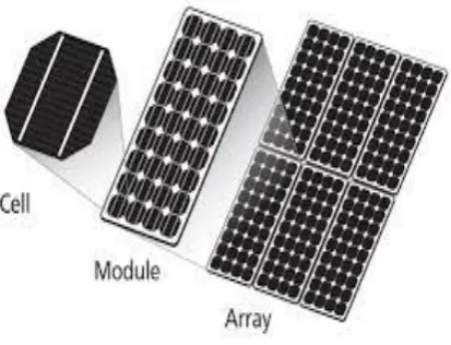
Solar cells are electrical devices in the solid form that help convert energy from sunlight into electric energy with the help of photovoltaic effect [3-5]. When a number of solar cells are clustered together, they are called solar modules which together save energy from sunlight. When a cluster of solar modules are assembled at a place, it results in a solar panel. The energy generated from this integrated module group is referred as solar power. The solar cells are also known as photovoltaic cells or the PV cells. As the name itself suggests, photo means light while voltaic refer to electricity. In other words, photovoltaic cells can help tap into the potential of solar energy to generate electric current. Due to the low voltage generated in a PV cell around 0.5V, many Photovoltaic cells are connected in series for high voltage and in parallel for high current requirements to form a Solar-PV module for desired output separate diodes may be required to avoid reverse currents [24-25]. When n number of such modules connected in and then in parallel to generate the required output voltage, it is termed as PV array as shown in figure 1.
Fig 1: Solar Photovoltaic System
III.
MULTI-LEVEL INVETERS (MLIs)
History of MLIs began in 1975 with Baker and Bannister. This first patent described a converter topology capable of producing multilevel voltage by connecting single phase inverter in series. The MLI offers several feature which raises its demand in present scenario such as; possible connection of series switching devices to obtain a high voltage output without the need of snubber circuit, significantly low THD in output waveforms, use of IGBT as switching device at high frequency to reduce losses, reduced torque ripple in induction machine etc.
VOLTAGE SOURCE
IGBT BASED
CURRENT SOURCE
INVERTER MULTI LEVEL
TWO LEVEL VOLTAGE
CURRENT SOURCE AC-AC
IN-DIRECT CONVERSION
AC-DC-AC DIRECT CONVERSION HIGH POWER
CONVERTER
THYRISTOR BASED
CYCLOCONVERTER
IGCT BASED
MATRIX CONVERTER
THYRISTOR BASED
LOAD COMMUTATED INVERTER
IGBT/IGBT BASED
MULTILEVEL-MATRIX CONVERTER
STAKED FLYING CAPACITOR
IGBT BASED
FLYING CAPACITOR
CASCADED
IGBT BASED
NPC HYBRID
TOPOLOGY
Fig 2: Topologies of multilevel Inverters A. NEUTRAL POINT CLAMPED TOPOLOGY
The diode clamped converter provides multiple voltages through connecting the phases to a series capacitors banks. The concept can be increased to number of levels by increasing the number of capacitors. Earlier this methods was only limited to three levels in which two capacitors connected across the dc bus resulting in one additional level that is the neutral point, so the terminology neutral point clamped (NPC) inverter was introduced in the theories [6][10][26-27].
Advantages:
• There is the reduction in THD as the increase in number of levels of the MLI comparatively to other methods. • The advantage is that single-phase NPC converters are that it is virtually immune from ground leakage currents.
• All of the phases share a common dc bus that minimizes the requirements of capacitance in the converter. Due to this NPC topology is not only convenient but also practical for uses such as a high-voltage back-to-back inter-connection or an adjustable speed drive.
• The capacitors can be pre-charged as a group. Efficiency is high for fundamental frequency switching.
Disadvantages:
• The number of part counts is more in neutral point clamped method which make the system costly comparatively.
• The number of clamping diodes required in system is related to the number of levels of the converter, which can be problem for systems with a high number of levels.
B. CASCADE H-BRIDGE TOPOLOGY
In cascade H-bridge there are several different configurations as well. This topology consists of series power conversion units, the voltage and power level may be conveniently scaled. A noticeable disadvantage of this cascade H-Bridge topology is large number of isolated voltages are required to supply each cell unit separately. In this study focus is on the increasing different levels in converters starting from basic three levels to the nine levels with their simulated results giving a comparison on using two different topologies neutral point (NCP) and cascade H-Bridge (CHB) type [6][10][26-27].
IV.
SIMULATION RESULTS
This paper presents a comparison of the most common topologies of MLIs interfaced with the PV system. Solar PV system is interfaced with the NPC and the CHB-MLI for different levels (three, five, seven and nine) and analysis is carried on the basis of the Total Harmonics Distortion (THD). The Fast Fourier technique (FFT) is used to calculate the THD. The PV system of 36 cells (each of 0.6V) is used in the MATLAB/Simulink to interface with the MLIs. All the related techniques used in this chapter are discussed in detail. The comparison are further tabulated and graphically represented for the both topologies and the outcome for the multilevel converters is concluded for the future researches and analysis. The MATLAB/Simulink models are presented for all the techniques used along with their output voltages [26]. The Total Harmonics Distortion calculated from the FFT is presented. The parameters values selected for solar cell is presented in Table 1
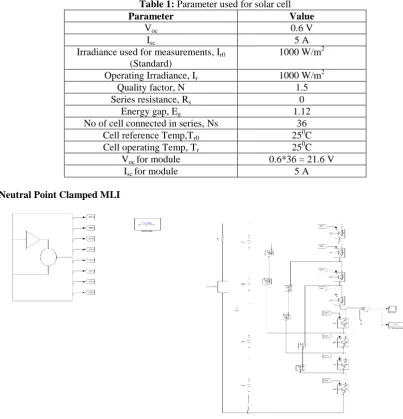
Table 1: Parameter used for solar cell
Parameter Value
Voc 0.6 V
Isc 5 A
Irradiance used for measurements, Ir0
(Standard)
1000 W/m2
Operating Irradiance, Ir 1000 W/m2
Quality factor, N 1.5
Series resistance, Rs 0
Energy gap, Eg 1.12
No of cell connected in series, Ns 36 Cell reference Temp,Tr0 250C
Cell operating Temp, Tr 250C
Voc for module 0.6*36 = 21.6 V
Isc for module 5 A
i)Neutral Point Clamped MLI
0 500 1000 1500 2000 2500 3000 3500 4000 -80 -60 -40 -20 0 20 40 60 80 Time (S) V o lt a g e ( V ) 5 -L E VE L 7 -L E VE L 9 -L E VE L
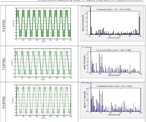
Fig 4: Output voltage waveform and FFT Analysis of NPC-MLI for 5, 7, 9 levels. ii) Cascade H-Bridge MLI
0 500 1000 1500 2000 2500 3000 3500 4000
-50 -40 -30 -20 -10 0 10 20 30 40 50 Time (S) V o lt a g e ( V )
0 500 1000 1500 2000 2500 3000 3500 4000
-100 -80 -60 -40 -20 0 20 40 60 80 100 Time (S) V o lt a g e ( V ) Discrete, Ts = 5e-05 s.
5 -L E VE L 7 -L E VE L 9 -L E VE L
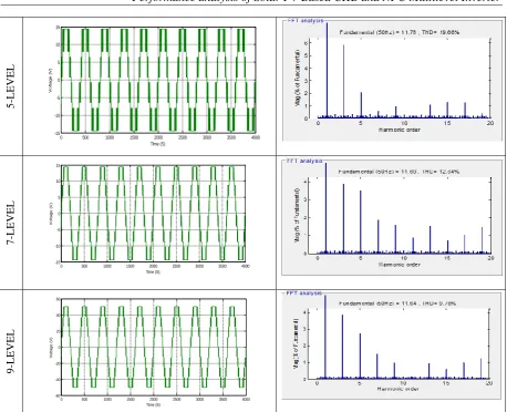
Fig 6: Output voltage waveform and FFT Analysis of CHB-MLI for 5, 7, 9 levels.
Figure 4 and 6 shows the output voltage waveform and FFT analysis of NPC-MLI and CHB-MLI respectively. From the figures it is cleared that THD of NPC is very low as compared to the CHB for the respective levels. The comparative analysis of THD and component requirement for the two topologies is presented in next session.
V.
COMPARATIVE ANALYSIS OF NPC-MLI AND CHB-MLI
Table 2: Comparative analysis of NPC-MLI and CHB-MLI with respect to the component requirement and THD analysis
Inverter level and
Type Parameter
Five level topology m=5
Nine level topology m=7
Five level topology m=9
Switching devices NPC CHB NPC CHB NPC CHB
Diodes 8 8 12 12 16 16
Clamping Diode 8 8 12 12 16 16
DC bus 12 0 30 0 30 0
Capacitors for clamping 4 2 6 3 8 4
THD% 25.69 19.66 15.09 12.64 11.56 9.78
From the Table 2 it is clear that the THD of the NPC-MLI is very low as compared to the CHB-MLI for the respective levels but NPC-MLI has the high cost of implementation. Hence choice among the two depends upon the application where they are employed.
VI. CONCLUSION
The MATLAB simulation model of grid connected cascade H-bridge and Neutral point clamped MLI up to nine levels is designed in this paper. With the increase in the voltage levels through NPC-MLI and CHB-MLI it reduces THD. Increasing the number of levels by these topologies is easily possible to large extends
0 500 1000 1500 2000 2500 3000 3500 4000
-15 -10 -5 0 5 10 15 TIme (S) V o lt a g e ( V )
0 500 1000 1500 2000 2500 3000 3500 4000
-15 -10 -5 0 5 10 15 TIme (S) V o lt a g e ( V )
0 500 1000 1500 2000 2500 3000 3500 4000
which is a new direction in this field. From the results it is clear that the THD of the NPC-MLI is very low as compared to the CHB-MLI for the respective levels but NPC-MLI has the high cost of implementation. Hence choices among the two depend upon the application where they are employed. A multilevel technique for converters ensures a reduction of output harmonics as a result of sinusoidal output voltages so ends up in reduce grid filters, system cost and complexity reduction. This study was to analysis the MLI for different levels using NPC and CHB for grid integrated operation of PV system and to analyze their THD. CHB is better in terms of switches count, more cost competent and low THD than NPC.
REFERENCES
[1]. Kumar, V., Pandey, A. S., & Sinha, S. K. (2016, March). Grid integration and power quality issues of wind and solar energy system: A review. In 2016 International Conference on Emerging Trends in Electrical Electronics & Sustainable Energy Systems (ICETEESES) (pp. 71-80). IEEE.
[2]. Grandi, G., Rossi, C., Ostojic, D., & Casadei, D. (2009). A new multilevel conversion structure for grid-connected PV applications. IEEE Transactions on Industrial Electronics, 56(11), 4416-4426.
[3]. Ulsrud, K., Winther, T., Palit, D., Rohracher, H., & Sandgren, J. (2011). The Solar Transitions research on solar mini-grids in India: Learning from local cases of innovative socio-technical systems. Energy for Sustainable Development, 15(3), 293-303.
[4]. ElNozahy, M. S., & Salama, M. M. A. (2013). Technical impacts of grid-connected photovoltaic systems on electrical networks—A review. Journal of Renewable and Sustainable Energy, 5(3), 032702.
[5]. Libo, W., Zhengming, Z., & Jianzheng, L. (2007). A single-stage three-phase grid-connected photovoltaic system with modified MPPT method and reactive power compensation. IEEE Transactions on Energy Conversion, 22(4), 881-886.
[6]. Corzine, K. (2005). Operation and design of multilevel inverters. Developed for the office of naval research.
[7]. De Oliveira, F. M., da Silva, S. A. O., Durand, F. R., Sampaio, L. P., Bacon, V. D., & Campanhol, L. B. (2016). Grid-tied photovoltaic system based on PSO MPPT technique with active power line conditioning. IET Power Electronics, 9(6), 1180-1191.
[8]. Molina, M. G., dos Santos, E. C., & Pacas, M. (2010, November). Improved power conditioning system for grid integration of photovoltaic solar energy conversion systems. In 2010 IEEE/PES Transmission and Distribution Conference and Exposition: Latin America (T&D-LA) (pp. 163-170). IEEE.
[9]. Daher, S., Schmid, J., & Antunes, F. L. (2008). Multilevel inverter topologies for stand-alone PV systems. IEEE transactions on industrial electronics, 55(7), 2703-2712.
[10]. Mohan, N., & Undeland, T. M. (2007). Power electronics: converters, applications, and design. John wiley & sons.
[11]. Zambra, D. A., Rech, C., & Pinheiro, J. R. (2010). Comparison of neutral-point-clamped, symmetrical, and hybrid asymmetrical multilevel inverters. IEEE Transactions on Industrial Electronics, 57(7), 2297-2306.
[12]. Kouro, S., Malinowski, M., Gopakumar, K., Pou, J., Franquelo, L. G., Wu, B. & Leon, J. I. (2010). Recent advances and industrial applications of multilevel converters. IEEE Transactions on industrial electronics, 57(8), 2553-2580.
[13]. Tolbert, L. M., & Peng, F. Z. (1998, February). Multilevel converters for large electric drives. In APEC'98 Thirteenth Annual Applied Power Electronics Conference and Exposition(Vol. 2, pp. 530-536). IEEE.
[14]. Vazquez, S., Leon, J. I., Carrasco, J. M., Franquelo, L. G., Galvan, E., Reyes, M., & Dominguez, E. (2009). Analysis of the power balance in the cells of a multilevel cascaded H-bridge converter. IEEE Transactions on Industrial Electronics, 57(7), 2287-2296.
[15]. Tolbert, L. M., & Peng, F. Z. (2000). Multilevel converters as a utility interface for renewable energy systems. In 2000 Power Engineering Society Summer Meeting (Cat. No. 00CH37134)(Vol. 2, pp. 1271-1274). IEEE.
[16]. Brando, G., Dannier, A., Del Pizzo, A., & Rizzo, R. (2010, September). A high performance control technique of power electronic transformers in medium voltage grid-connected PV plants. In The XIX International Conference on Electrical Machines-ICEM 2010 (pp. 1-6). IEEE.
[20]. Tolbert, L. M., & Habetler, T. G. (1999). Novel multilevel inverter carrier-based PWM method. IEEE Transactions on industry applications, 35(5), 1098-1107.
[21]. Barater, D., Buticchi, G., Crinto, A. S., Franceschini, G., & Lorenzani, E. (2012). Unipolar PWM strategy for transformerless PV grid-connected converters. IEEE Transactions on Energy Conversion, 27(4), 835-843.
[22]. Safia, M., & Kumar, T. P. (2013). Design and Simulation of Grid Connected PV system Using Multilevel Inverters.
[23]. Kulkarni, V., & Nehete, R. Simulation and Analysis of Photo-Voltaic (PV) based Solar Inverter System. International Journal of Soft Computing and Engineering (IJSCE), ISSN, 2231-2307.
[24]. Ahmad, Z., & Singh, S. N. (2013). Modeling and Control of Grid Connected Photovoltaic System-A Review. International Journal of Emerging Technology and Advanced Engineering, 3(3), 2250-2459. [25]. Karki, P., & Adhikary, B. (2013, October). MATLAB/Simulink based modeling and simulation of
gird-connected solar photovoltaic system in distribution power network. In Fifth International Conference on Power and Energy Systems, Kathmandu, Nepal (pp. 28-30).
[26]. Rathore, S., Kirar, M. K., & Bhardwaj, S. K. (2015). Simulation of cascaded h-bridge multilevel inverter using pd pod apod Techniques. Electrical & Computer Engineering: An International Journal (ECIJ), 4(3), 27-41.
[27]. Shehu, G. S., Kunya, A. B., Shanono, I. H., & Yalçınöz, T. (2016). A review of multilevel inverter topology and control techniques. Journal of Automation and Control Engineering.