ISSN: 2278-067X, Volume 1, Issue 12 (July 2012), PP.33-40
www.ijerd.com
Modeling & Simulation of DSTATCOM for Power Quality
Improvement
N.Srinivasa Rao
1, Dr G.V.Siva Krishna Rao
21
Associate professor, Department of Electrical & Electronics Engineering, Sri sai Aditya institute of Science
and Technology , Surampalem,E.G.District A.P, India.
2
Professor, Department of Electrical Engineering, Andhra university, visakhapatnam ,A.P, India.
Abstract––
A Power quality problem is an occurrence manifested as a nonstandard voltage, current or frequency that results in a failure or a mis-operation of end user equipments. Utility distribution networks, sensitive industrial loads and critical commercial operations suffer from various types of outages and service interruptions which can cost significant financial losses. With the restructuring of power systems and with shifting trend towards distributed and dispersed generation, the issue of power quality is going to take newer dimensions. In developing countries like India, where the variation of power frequency and many such other determinants of power quality are themselves a serious question, it is very vital to take positive steps in this direction .This paper presents a study on the modeling of a STATCOM (Static Synchronous Compensator) used for reactive power compensation on a distribution network. This paper deals with the simulation of distribution static synchronous compensator (DSTATCOM) for improving power quality of a distribution system feeding linear as well as non-linear loads. Nowadays, there are an increasing number of non-linear loads which inject harmonics into the system. A three-phase insulated gate bipolar transistor- (IGBT-) based current controlled voltage source inverter with a DC bus capacitor known as a DSTATCOM is used for power factor correction, harmonic compensation and for providing required reactive power to the load. A model of DSTATCOM connected to a power distribution system feeding linear and non-linear loads (diode bridge rectifier with R and R-C) is developed for predicting the behavior of system under transient conditions. Simulation is carried out in standard MATLAB environment using Simulink and power system blockset toolboxes. Finally the performance of DSTATCOM under various fault conditions is investigated.Keywords––
D-STATCOM, Voltage Sags, Voltage Source Converter (VSC).I.
INTRODUCTION
One of the most common power quality problems today is voltage dips. A voltage dip is a short time (10 ms to 1 minute) event during which a reduction in r.m.s voltage magnitude occurs. It is often set only by two par ameters, depth/magnitude and duration. The voltage dip magnitude is ranged from 10% to 90% of nominal voltage (which corresponds to 90% to 10% remaining voltage) and with a duration from half a cycle to 1 min. In a three-phase system a voltage dip is by nature a three-phase phenomenon, which affects both the phase-to-ground and phase-to-phase voltages. A voltage dip is caused by a fault in the utility system, a fault within the customer‟s facility or a large increase of the loa d current, like starting a motor or transformer energizing. Typical faults are single-phase or multiple-phase short circuits, which leads to high currents. The high current results in a voltage drop over the network impedance. At the fault location the voltage in the faulted phases drops close to zero, whereas in the non-faulted phases it remains more or less unchanged [1, 2].
Voltage dips are one of the most occurring power quality problems. Off course, for an industry an outage is worse, than a voltage dip, but voltage dips occur more often and cause severe problems and economical losses. Utilities often focus on disturbances from end-user equipment as the main power quality problems. This is correct for many disturbances, flicker, harmonics, etc., but voltage dips mainly have their origin in the higher voltage levels. Faults due to lightning, is one of the most common causes to voltage dips on overhead lines. If the economical losses due to voltage dips are significant, mitigation actions can be profitable for the customer and even in some cases for the utility. Since there is no standard solution which will work for every site, each mitigation action must be carefully planned and evaluated. There are different ways to mitigate voltage dips, swell and interruptions in transmission and distribution systems. At present, a wide range of very flexible controllers, which capitalize on newly available power electronics components, are emerging for custom power applications [3, 4]. Among these, the distribution static compensator and the dynamic voltage restorer are most effective devices, both of them based on the VSC principle.
STATCOM is often used in transmission system. When it is used in distribution system, it is called D-STATCOM
It is expected that the D-STATCOM will replace the roles of SVC in near future. D-STATCOM and STATCOM are different in both structure and function, while the choice of control strategy is related to the main-circuit structure and main function of compensators [3], so D-STATCOM and STATCOM adopt different control strategy. At present, the use of STATCOM is wide and its strategy is mature, while the introduction of D-STATCOM is seldom reported. Many control techniques are reported such as instantaneous reactive power theory (Akagi et al., 1984), power balance theory, etc. In this paper, an indirect current control technique (Singh et al., 2000a,b) is employed to obtain gating signals for the Insulated Gate Bipolar Transistor (IGBT) devices used in current controlled voltage source inverter (CC-VSI) working as a DSTATCOM. A model of DSTATCOM is developed using MATLAB for investigating the transient analysis of distribution system under balanced/unbalanced linear and non-linear three-phase and single-phase loads (diode rectifier with R and R-C load). Simulation results during steady-state and transient operating conditions of the DSTATCOM are presented and discussed to demonstrate power factor correction, harmonic elimination and load balancing capabilities of the DSTATCOM system [5-10].
II.
DISTRIBUTION
STATIC
COMPENSATOR
(D-STATCOM)
2.1 Principle of DSTATCOM
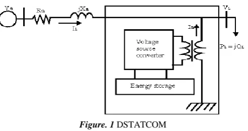
A D-STATCOM (Distribution Static Compensator), which is schematically depicted in Fig.1, consists of a two-level Voltage Source Converter (VSC), a dc energy storage device, a coupling transformer connected in shunt to the distribution network through a coupling transformer. The VSC converts the dc voltage across the storage device into a set of three-phase ac output voltages. These voltages are in phase and coupled with the ac system through the reactance of the coupling transformer. Suitable adjustment of the phase and magnitude of the D-STATCOM output voltages allows effective control of active and reactive power exchanges between the DSTATCOM and the ac system. Such configuration allows the device to absorb or generate controllable active and reactive power.
The VSC connected in shunt with the ac system provides a multifunctional topology which can be used for up to three quite distinct purposes:
1. Voltage regulation and compensation of reactive power; 2. Correction of power factor; and
3. Elimination of current harmonics.
Here, such device is employed to provide continuous voltage regulation using an indirectly controlled converter.
Figure. 1 DSTATCOM
Fig. 1 the shunt injected current Ish corrects the voltage sag by adjusting the voltage drop across the system
impedance Zth. The value of Ish can be controlled by adjusting the output voltage of the converter. The shunt injected current
Ish can be written as,
Ish = IL – IS = IL – ( Vth – VL ) / Zth
Ish /_η = IL /_- θ
through AC system and regulates missing voltages. These voltages are in phase and coupled with the AC system through the reactance of coupling transformers. Suitable adjustment of the phase and magnitude of the DSTATCOM output voltages allows effectives control of active and reactive power exchanges between D-STATCOM and AC system. In addition, the converter is normally based on some kind of energy storage, which will supply the converter with a DC voltage [10].
2.3 Controller for DSTATCOM
The three-phase reference source currents are computed using three-phase AC voltages (vta, vtb and vtc) and DC bus voltage (Vdc) of DSTATCOM. These reference supply currents consist of two components, one in-phase (Ispdr) and another in quadrature (Ispqr) with the supply voltages. The control scheme is represented in Fig. 2. The basic equations of control algorithm of DSTATCOM are as follows.
2.3.1 Computation of in-phase components of reference supply current
The instantaneous values of in-phase component of reference supply currents (Ispdr) is computed using one PI controller over the average value of DC bus voltage of the DSTATCOM (vdc) and reference DC voltage (vdcr) as
where Vde(n) Vdcc-Vdcn) denotes the error in Vdcc and average value of Vdc Kpd and Kid are proportional and integral gains of the DC bus voltage PI controller. The output of this PI controller (Ispdr) is taken as amplitude of in-phase component of the reference supply currents. Three-phase in-phase components of the reference supply currents (isadr, isbdr and iscdr) are computed using the in-phase unit current vectors (ua, ub and uc) derived from the AC terminal voltages (vtan, vtbn and vtcn), respectively.
where Vtm is amplitude of the supply voltage and it is computed as
The instantaneous values of in-phase component of reference supply currents (isadr, isbdr and iscdr) are computed as
2.3.2 Computation of quadrature components of reference supply current
The amplitude of quadrature component of reference supply currents is computed using a second PI controller over the amplitude of supply voltage (vtm) and its reference value (vtmr)
whereVac= Vtmc-Vmc(n)denotes the error in Vtmc and computed value Vtmn from Equation (3) and Kpqand Kiqare the proportional and integral gains of the second PI controller.
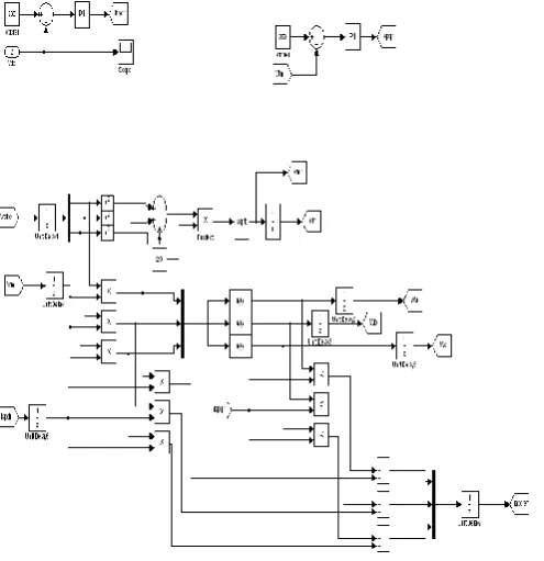
Figure. 2 Control method for DTSATCOM
2.3 Computation of total reference supply currents
Three-phase instantaneous reference supply currents (isar, isbr and iscr) are computed by adding in-phase (isadr, isbdr and iscdr) and quadrature components of supply currents (isaqr, isbqr and iscqr) as
A hysteresis pulse width modulated (PWM) current controller is employed over the reference (isar, isbr and iscr) and sensed supply currents (isa, isb and isc) to generate gating pulses for IGBTs of DSTATCOM.
III.
MATAB/SIMULINK
MODELING
OF
DSTATCOM
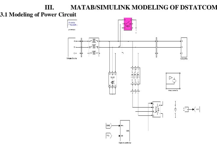
Fig. 6 shows the complete MATLAB model of DSTATCOM along with control circuit. The power circuit as well as control system are modelled using Power System Blockset and Simulink. The grid source is represented by three-phase AC source. Three-phase AC loads are connected at the load end. DSTATCOM is connected in shunt and it consists of PWM voltage source inverter circuit and a DC capacitor connected at its DC bus. An IGBT-based PWM inverter is implemented using Universal bridge block from Power Electronics subset of PSB. Snubber circuits are connected in parallel with each IGBT for protection. Simulation of DSTATCOM system is carried out for linear and non-linear loads. The linear load on the system is modelled using the block three-phase parallel R-L load connected in delta configuration. The non-linear load on the system is modelled using R and R-C circuits connected at output of the diode rectifier. Provision is made to connect loads in parallel so that the effect of sudden load addition and removal is studied. The feeder connected from the three-phase source to load is modelled using appropriate values of resistive and inductive components.
3.2 Modeling of Control Circuit
Figure below shows the control algorithm of DSTATCOM with two PI controllers. One PI controller regulates the DC link voltage while the second PI controller regulates the terminal voltage at PCC. The in-phase components of DSTATCOM reference currents are responsible for power factor correction of load and the quadrature components of supply reference currents are to regulate the AC system voltage at PCC.
The output of PI controller over the DC bus voltage (Ispdr) is considered as the amplitude of the in-phase component of supply reference currents and the output of PI controller over AC terminal voltage (Ispqr) is considered as the amplitude of the quadrature component of supply reference currents. The instantaneous reference currents (isar, isbr and iscr) are obtained by adding the in-phase supply reference currents (isadr, isbdr and iscdr) and quadrature supply reference currents (isaqr, isbqr and iscqr). Once the reference supply currents are generated, a carrierless hysteresis PWM controller is employed over the sensed supply currents (isa, isb and isc) and instantaneous reference currents (isar, isbr and iscr) to generate gating pulses to the IGBTs of DSTATCOM. The controller controls the DSTATCOM currents to maintain supply currents in a band around the desired reference current values. The hysteresis controller generates appropriate switching pulses for six IGBTs of the VSI working as DSTATCOM.
IV.
SIMULATION
RESULTS
Here Simulation results are presented for four cases. In case one load is linear RL load, in case two non linear R load, in case three non linear RC load, and in case four we have considered line disturbance like single line to ground fault (SLG), without DSTATCOM and with DSTATCOM.
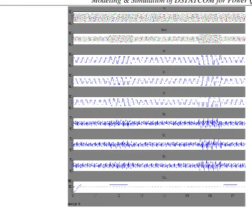
4.1 Case one
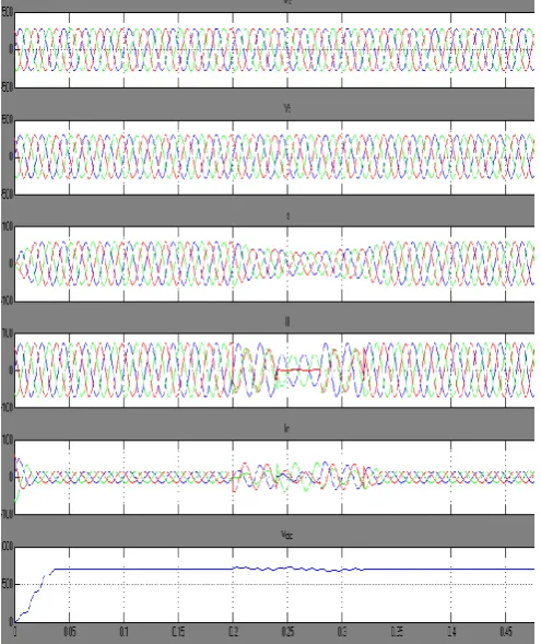
Supply currents (isa, isb and isc), compensator currents (ica, icb and icc) and DC bus voltage (vdc) settle to steady-state values within a cycle for any type of change in load.
Figure. 7 Simulation results for Linear RL Load
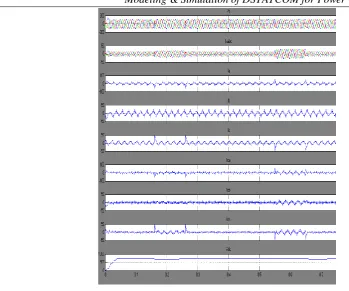
Figure. 9 Simulation results Non- Linear R Load
At t =0.16 sec, the DC load resistance is changed from 15 to 10 ohm to increase the loading thereby the power absorbed changes from 21 to 30 kW. Consequently, load, supply and DSTATCOM currents increase to provide demanded active and reactive power to the load. The increased load on the rectifier reflects in the form of undershoot in DC link voltage. At t =0.26 sec, the load resistance is changed back to 15 ohm and an overshoot is observed now, which settles down within a few cycles due to action of PI controller. Results show that the supply currents are balanced, sinusoidal and in-phase with the supply voltages.
4.3 Case three
Figure. 10 Simulation results Non- Linear RC Load
V.
CONCLUSION
DSTATCOM system is an efficient mean for mitigation of PQ disturbances introduced to the grid by DERs. DSTATCOM compensator is a flexible device which can operate in current control mode for compensating voltage variation, unbalance and reactive power and in voltage control mode as a voltage stabilizer. The latter feature enables its application for compensation of dips coming from the supplying network. The simulation results show that the performance of DSTATCOM system has been found to be satisfactory for improving the power quality at the consumer premises. DSTATCOM control algorithm is flexible and it has been observed to be capable of correcting power factor to unity, eliminate harmonics in supply currents and provide load balancing. It is also able to regulate voltage at PCC. The control algorithm of DSTATCOM has an inherent property to provide a self-supporting DC bus of DSTATCOM. It has been found that the DSTATCOM system reduces THD in the supply currents for non-linear loads. Rectifier-based non-linear loads generated harmonics are eliminated by DSTATCOM. When single-phase rectifier loads are connected, DSTATCOM currents balance these unbalanced load currents.
REFERENCES
[1]. A.E. Hammad, Comparing the Voltage source capability of Present and future Var Compensation Techniques in Transmission
System, IEEE Trans, on Power Delivery . volume 1. No.1 Jan 1995.
[2]. G.Yalienkaya, M.H.J Bollen, P.A. Crossley, “Characterization of Voltage Sags in Industrial Distribution System”, IEEE
transactions on industry applications, volume 34, No. 4, July/August, PP.682-688, 1999.
[3]. Haque, M.H., “Compensation Of Distribution Systems Voltage sags by DVR and D-STATCOM”, Power Tech Proceedings,
2001 IEEE Porto, Volume 1, PP.10-13, September 2001.
[4]. Anaya-Lara O, Acha E., “Modeling and Analysis Of Custom Power Systems by PSCAD/EMTDC”, IEEE Transactions on Power
Delivery, Volume 17, Issue: 2002, Pages: 266-272.
[5]. Bollen, M.H.J.,”Voltage sags in Three Phase Systems”, Power Engineering Review, IEEE, Volume 21, Issue :9, September