www.the-cryosphere.net/9/1735/2015/ doi:10.5194/tc-9-1735-2015
© Author(s) 2015. CC Attribution 3.0 License.
Improving Arctic sea ice edge forecasts by assimilating
high horizontal resolution sea ice concentration data
into the US Navy’s ice forecast systems
P. G. Posey1, E. J. Metzger1, A. J. Wallcraft1, D. A. Hebert1, R. A. Allard1, O. M. Smedstad2, M. W. Phelps3, F. Fetterer4, J. S. Stewart5, W. N. Meier6, and S. R. Helfrich7
1Naval Research Laboratory, Stennis Space Center, MS, USA
2Vencore Services and Solutions, Inc., Stennis Space Center, MS, USA 3Jacobs Technology Inc., Stennis Space Center, MS, USA
4National Snow and Ice Data Center, Boulder, CO, USA 5J. Scott Stewart of Exploratory Thinking, Longmont, CO, USA 6NASA Goddard Space Flight Center, Greenbelt, MD, USA 7US National Ice Center, Suitland, MD, USA
Correspondence to: P. G. Posey ([email protected])
Received: 4 March 2015 – Published in The Cryosphere Discuss.: 9 April 2015 Revised: 27 July 2015 – Accepted: 5 August 2015 – Published: 31 August 2015
Abstract. This study presents the improvement in ice edge error within the US Navy’s operational sea ice forecast systems gained by assimilating high horizontal resolution satellite-derived ice concentration products. Since the late 1980’s, the ice forecast systems have assimilated near real-time sea ice concentration derived from the Defense Me-teorological Satellite Program (DMSP) Special Sensor Mi-crowave/Imager (SSMI and then SSMIS). The resolution of the satellite-derived product was approximately the same as the previous operational ice forecast system (25 km). As the sea ice forecast model resolution increased over time, the need for higher horizontal resolution observational data grew. In 2013, a new Navy sea ice forecast system (Arc-tic Cap Nowcast/Forecast System – ACNFS) went into op-erations with a horizontal resolution of ∼3.5 km at the North Pole. A method of blending ice concentration obser-vations from the Advanced Microwave Scanning Radiome-ter (AMSR2) along with a sea ice mask produced by the National Ice Center (NIC) has been developed, resulting in an ice concentration product with very high spatial resolu-tion. In this study, ACNFS was initialized with this newly developed high resolution blended ice concentration prod-uct. The daily ice edge locations from model hindcast sim-ulations were compared against independent observed ice
edge locations. ACNFS initialized using the high resolution blended ice concentration data product decreased predicted ice edge location error compared to the operational system that only assimilated SSMIS data. A second evaluation as-similating the new blended sea ice concentration product into the pre-operational Navy Global Ocean Forecast System 3.1 also showed a substantial improvement in ice edge location over a system using the SSMIS sea ice concentration product alone. This paper describes the technique used to create the blended sea ice concentration product and the significant im-provements in ice edge forecasting in both of the Navy’s sea ice forecasting systems.
1 Introduction
2014, indicate high year-to-year variability in the ice cover and also in the spatial distribution of the ice (i.e., where open water forms) (Perovich et al., 2014). In this rapidly chang-ing Arctic environment (Meier et al., 2014), it is likely that Arctic shipping will increase over the next decade. This, in turn, will demand an increase in US military presence in the Arctic. As the US military presence increases in this region, it is imperative to provide as accurate a sea ice forecast as possible.
Currently, the Navy uses two systems to predict ice condi-tions: the Arctic Cap Nowcast/Forecast System (ACNFS) for the Northern Hemisphere as well as the Global Ocean Fore-cast System (GOFS 3.1). Prior to 2 February 2015, the ice concentration fields from both ACNFS and GOFS 3.1 had been updated with satellite-derived ice concentrations at a gridded resolution of approximately 25 km using the US De-fense Meteorological Satellite Program (DMSP) Special Sensor Microwave Imager/Sounder data (SSMIS). SSMIS has higher spatial resolution (12.5 km gridded) for high fquency (85–91 GHz) channels. However, most algorithms re-quire the lower resolution channels, limiting the gridded res-olution to 25 km, with the effective resres-olution dependent on the frequency of each channel used in the algorithm. Dur-ing 2012, a 10 km satellite-derived ice concentration product from Advanced Microwave Scanning Radiometer (AMSR2) on the Japan Aerospace Exploration Agency (JAXA) Global Change Observation Mission – Water (GCOM-W) platform became available. This higher horizontal resolution sea ice information derived from satellite observations was critically needed for existing high resolution ice models. Also, dur-ing 2012 the National Oceanic and Atmospheric Administra-tion (NOAA) NaAdministra-tional Ice Center (NIC) recommended that a greater effort be undertaken to assimilate analyzed data that they produce as well as other satellite sources into the Navy’s models in order to improve the forecasted ice edge location, especially during the summer season.
Recently, investigators at the National Snow and Ice Data Center (NSIDC), National Atmospheric and Space Adminis-tration (NASA), NIC and Naval Research Laboratory (NRL) developed a gridded ice concentration product that uses the daily observations from the Interactive Multisensor Snow and Ice Mapping System (IMS) (Helfrich et al., 2007; NIC, 2008) as well as data from the new higher resolution AMSR2 passive microwave sensor. The resolution of this blended data product is 4 km; much closer to the resolution of Navy ice forecasting systems than the SSMIS data. This study examines the impact on ice edge forecasts of assimilating this new, high resolution blended data into both ACNFS and GOFS 3.1.
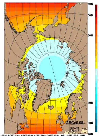
Figure 1. ACNFS and GOFS 3.1 model grid resolution (km) for the Arctic region.
2 System descriptions, data and methods 2.1 System descriptions
Currently, the Navy uses ACNFS to predict conditions in all ice-covered areas poleward of 40◦N, with a grid resolution of approximately 3.5 km at the North Pole (Fig. 1). ACNFS graphical products are publically available from http:// www7320.nrlssc.navy.mil/hycomARC. In September 2014, GOFS 3.1 was transitioned to the Naval Oceanographic Of-fice (NAVOCEANO), and is presently in the final operational testing phase. When GOFS 3.1 becomes operational, it will replace ACNFS and provide a global sea ice prediction ca-pability including both the Arctic and the Antarctic. ACNFS and GOFS 3.1 are based on the HYbrid Coordinate Ocean Model (HYCOM) (Metzger et al., 2015) coupled to the Los Alamos National Laboratory Community Ice CodE (CICE) version 4.0 (Hunke and Lipscomb, 2008). Data assimilation is provided by the Navy Coupled Ocean Data Assimilation (NCODA) system (Cummings and Smedstad, 2014).
based on yesterday’s 24 h forecast along with available ob-servations. The ocean analysis variables include temperature, salinity, geopotential and the vector velocity components that are all analyzed simultaneously and provide corrections to the next model forecast in a sequential incremental update. The ice concentration analysis assimilates SSMIS and pro-vides an ice concentration field that is directly inserted into the ice model. One major drawback in using SSMIS is its low spatial resolution of 25 km, which is much coarser than the near pole 3.5 km resolution of both ACNFS and GOFS 3.1.
ACNFS has undergone validation by NRL (Posey et al., 2010), has been declared operational (September 2013) and runs daily at NAVOCEANO. GOFS 3.1 was transitioned to NAVOCEANO on 26 September 2014 (Metzger et al., 2015) and is undergoing the final operational testing by NAVO-CEANO and the NIC. This new ice forecast system is ex-pected to be declared operational in summer/fall 2015. The NIC presently uses ACNFS output and in the near future (once declared operational) will use GOFS 3.1 output to im-prove the accuracy and resolution of the analyzed ice edge location.
2.2 Passive microwave
Several methods have been developed to estimate sea ice concentration from passive microwave brightness tempera-tures, generally via empirically derived algorithms based on differences or ratios between the passive signatures of ice and open water at different microwave frequencies and polariza-tions (e.g., Comiso and Nishio, 2008; Markus and Cavalieri, 2000). Since 1979, these algorithms have been applied to a series of multi-channel microwave radiometers such as the SSMIS.
The AMSR on the NASA Earth Observing System (EOS) Aqua platform (AMSR-E) operated from 2002 until the sen-sor ceased normal operations in October 2011. A follow-on sensor, AMSR2, was launched in May 2012 on the JAXA GCOM-W platform. The AMSR2 sensor has a much higher spatial resolution (instantaneous field of view, IFOV) than SSMIS and slightly higher than AMSR-E. For example, at the 19 GHz channels, SSMIS has an IFOV of approximately 70 km×45 km, AMSR-E is 27 km×16 km, and AMSR2 is 24 km×16 km (Kunkee et al., 2008; Imaoka et al., 2010). The higher spatial resolution of these new instruments allows for a higher gridded resolution sea ice concentration product (12.5 km for AMSR-E and 10 km for AMSR2 vs. 25 km for SSMIS). The standard sea ice concentration product hosted by JAXA, and used in this study, was derived using the Bootstrap algorithm. Products derived using other algorithms are also available, including one from the Universities of Hamburg and Bremen that incorporate the higher resolution 89 GHz channels that are capable of capturing finer details within the ice pack (Beitsch et al., 2014). The higher resolu-tion channels are however more subject to atmospheric
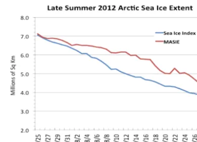
influ-Figure 2. Arctic sea ice extent (million km2) calculated using passive microwave data (blue) and the Multisensor Analyzed Sea Ice Extent (MASIE) product (red) for 25 July–28 August 2012. The passive microwave data are from the SSMIS on board the DMSP F17 satellite.
ences, particularly near the ice edge and the lower frequency channels are needed to remove false ice returns.
Problems associated with the interpretation of sea ice sig-natures in passive microwave data during summer months have been well documented (e.g., Cavalieri et al., 1990; Glo-ersen et al., 1978; Campbell et al., 1980). Summer sea ice concentrations are more uncertain than winter concentrations because of the presence of moist snow, wet ice surfaces and melt ponds. By confusing water atop sea ice with open ocean, passive microwave products tend to underestimate the ice concentration within the pack ice, and may not detect ice at all in some cases, even when ice is present in concentra-tions considerably greater than 15 %. Broad expanses of ice at relatively low concentration often make up the marginal ice zone (MIZ), and passive microwave products often place the ice edge farther poleward than in actuality, resulting in an underestimation of Arctic-wide ice extent relative to more accurate methods used in human-derived analyses.
also that the IMS/MASIE product has limitations as well. Analysts at the NIC use source data for IMS that can vary in quantity and quality depending on, for example, the satel-lite coverage. This may cause inconsistency over time (Meier et al., 2015) and some subjectivity will be imposed on the product due to the use of human analysis. For example, oc-casional large jumps in total extent from one day to the next were discovered; these were likely the result of limited SAR or visible/infrared data and/or limited human resources for analysis.
2.3 Interactive Multisensor Snow and Ice Mapping System (IMS) and Multisensor Analyzed Sea Ice Extent (MASIE)
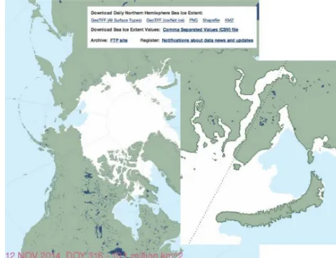
The IMS is an operational ice analysis produced by the NIC daily and valid at 00:00 UTC. IMS is an ice and snow mask product where sea ice is indicated when ice concentration is estimated to be greater than 40 % and open water where ice concentration is estimated to be less than 40 %. Hu-man analysis of all available satellite imagery including vis-ible/infrared (VIS/IR), synthetic aperture radar (SAR), scat-terometer and passive microwave yields a daily map of sea ice extent at 4 km spatial resolution. The IMS documentation (NIC, 2008) lists 28 potential sources for snow and ice in-formation. Most, but not all, of these sources are from satel-lite sensors. The MASIE product documentation (NIC and NSIDC, 2010) has additional information on how IMS fields are produced. The IMS ice fields are repackaged into several user-friendly formats to create the MASIE product available to the public from the NSIDC (NIC and NSIDC, 2010). Fig-ure 3 is a sample of a daily MASIE product.
The IMS/MASIE ice map for any particular day is par-tially the product of subjective interpretation and is not actly reproducible. However; each daily IMS/MASIE ice ex-tent field is produced according to fixed standards and quan-tified as areal coverage with set metrics. This contrasts with the operational chart products, where the NIC analysts have more flexibility with which to meet changing user needs.
We base our assertion that the IMS/MASIE product is a more reliable indicator of the presence or absence of ice than AMSR2 data due to several factors. Primarily, the manual analysis of numerous data sources is more dependable than a passive microwave concentration product alone. There are also several situations when the passive microwave’s sig-nature is identical to that of open water when sea ice is present (e.g., surface water on top of ice during the sum-mer, thin ice at any time of year) or to that of ice when ice is not present (e.g. “weather effects” from presence of wind/aerosols and “land spillover” from the field of view be-ing partly over land and partly over open water). In addition, NIC analysts have access to data sources that are of higher resolution than AMSR2. These factors lend a higher quality to the IMS/MASIE product.
Figure 3. Sample MASIE product (with zoomed Kara Sea region inset on right) valid on 12 November 2014. White indicates ice-covered areas.
Meier et al. (2015), compare passive microwave-derived ice extent with ice extent from IMS/MAISE annually and seasonally. While the magnitude of differences varied from day to day, in general a pattern was found in which IMS/MASIE-derived ice extent was larger than that from passive microwave through most of the year, but with two distinct periods – in late spring (May, June) during melt onset, and late summer (late September, October) during freeze-up. These are both periods of rapid transition in sur-face properties that passive microwave sensors are sensi-tive to, and that likely contribute to these discrepancies. As noted above, some instances were found of unrealistic large changes in IMS/MASIE ice extent over just a day, highlight-ing the potential inconsistency in the human-based data fu-sion and analysis. These large changes are likely a result of limited satellite imagery due to satellite coverage (SAR) or clouds (visible/infrared) and/or resources available for the manual analysis.
In this study, the MASIE product was used in an ACNFS hindcast from July 2012–July 2013, while the IMS prod-uct was used in ACNFS and GOFS 3.1 hindcasts from June 2014–August 2014. As stated above, these two prod-ucts (MASIE and IMS) are identical in data values but differ in format and location of the data source; MASIE is delivered from the NSIDC, while IMS comes from the NIC.
2.4 Blended IMS/MASIE+AMSR2
mul-tiple data sources that make the IMS/MASIE product. In 2012 AMSR2 ice concentration became available in real-time (https://gcom-w1.jaxa.jp/auth.html), and, along with the IMS/MASIE product, could be evaluated for daily ini-tialization in order to improve the forecasted ice edge loca-tion, especially during the summer season. Both data prod-ucts (AMSR2 and IMS/MASIE) are available (within 24 h) for assimilation in daily operational forecasting applications. In the initial yearlong study (described in Sect. 3.1), a grid-ded AMSR2 and MASIE blengrid-ded product was generated on a 4 km grid and input into NCODA to produce an ice anal-ysis that was then read into CICE. On restart, CICE directly inserts the NCODA analysis of ice concentration and adjusts other fields (e.g., volume and energy of melting for both ice and snow) for consistency. However, in ACNFS, we only use the NCODA ice concentration analysis “near” the ice edge as follows:
1. if model≤NCODA analysis
– use model where NCODA analysis>50 %; – blend model and NCODA analysis for
concentra-tions that fall within 25 %<NCODA<50 %; – use NCODA analysis where NCODA
analy-sis<25 %.
2. if model>NCODA analysis – use model where model>30 %;
– blend model and NCODA analysis for concentra-tions that fall within 15 %<model<30 %; – use NCODA analysis for model<15 %.
CICE adjusts its water temperature based on the addition or removal of ice. If ice is added to an initially ice-free grid cell, the ocean temperature is cooled to prevent the ice from immediately melting. Conversely, if ice is removed from a grid cell that had ice, the ocean temperature is warmed to prevent the model from immediately forming ice.
The blended product converts ice extent into concentration using the following rules:
1. if IMS/MASIE has no ice and AMSR2 has an ice con-centration value, set the ice concon-centration to 0 %; 2. if IMS/MASIE indicates ice and AMSR2 has<70 %
ice concentration for that grid cell, make the ice con-centration 70 %;
3. if IMS/MASIE indicates ice and AMSR2 has an ice concentration value>70 % for that grid cell, then use the AMSR2 ice concentration value.
The IMS/MASIE ice mask has a 40 % ice concentration threshold, meaning the actual concentration within each ice cell falls somewhere between 40 and 100 %, based on an an-alyst’s subjective estimation. The mid-point, 70 %, is used
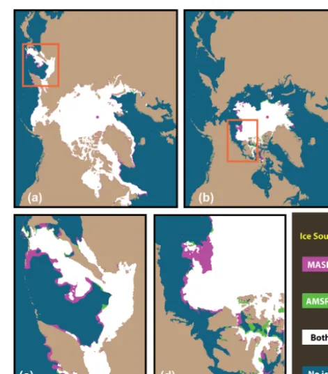
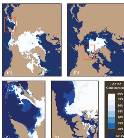
Figure 4. AMSR2 and IMS/MASIE ice extent differences during (a) 15 March 2014 – winter and (b) 15 September 2014 – summer. Magenta: IMS/MASIE shows ice where AMSR2 does not show ice greater than 15 %. Green: AMSR2 shows ice where IMS/MASIE does not. White: both indicate ice. Blue: both indicate no ice. A closer view of the Sea of Okhotsk region in winter (c) illustrates where the passive microwave data are failing to detect thin ice around the Kamchatka Peninsula and near the ice edge in the Sea of Okhotsk. The much smaller areas where AMSR2 detects ice and IMS/MAISE does not (shown in green), may be due to a mismatch in data acquisition time. The Beaufort Sea on this day in summer (d) has a large expanse of ice not detected by the AMSR2 data.
Figure 5. AMSR2 and IMS/MASIE blended ice concentration (%) products for (a) 15 March 2014 – winter and (b) 15 September 2014 – summer. If IMS/MASIE and AMSR2 indicate ice, then the great-est of 70 % or the AMSR2 ice concentration value is used. If IMS/MASIE indicates ice and AMSR2 has none, then 70 % (light blue) is used as ice concentration value. The zoomed areas (c) and (d) can be compared with (c) and (d) in Fig. 4 to see the effect of filling with 70 % in the blended product. Note the detail in the Beaufort Sea ice edge. A prototype version of the blended product is available from NSIDC (Fetterer et al., 2015).
Figure 5 shows the final blended AMSR2 and IMS/MASIE ice concentration product during the win-ter (15 March 2014) and summer (15 September 2014) days of Fig. 4. The magenta “MASIE only” areas of Fig. 4 are assigned a value of 70 % (dark blue) in the blended ice concentration product while the green “AMSR only” areas are assigned a value of 0 %. There are no ice concentration values between 0 and 70 % in the blended product. The homogenous expanses of ice at 70 % are more noticeable in the summer when the passive microwave underestimates the extent of ice over large areas. Also note, that the AMSR2 “land spillover” effect of false detection that can occur along coasts is mitigated by the IMS/MASIE ice mask product. Some of the areas shown in green in Fig. 4 can be attributed to land spillover.
3 Assimilation study and results
3.1 ACNFS assimilating AMSR2 ice concentration and MASIE ice mask
For this study, ACNFS assimilated three different sources of sea ice concentration for the time period July 2012 through July 2013: (1) SSMIS only, (2) AMSR2 only and (3) blended AMSR2+MASIE. All three products used the same assim-ilation methodology to update the initial ACNFS fields. The 6 h forecast ice edge derived from ACNFS hindcasts of sea ice concentration assimilating the three different products was compared to the independent ice edge obtained from the NIC valid 00:00 UTC. The NIC analyzed ice edge product is generated daily by an ice analyst for the full Arctic region using a variety of satellite sources (visible images, infrared, scatterometer, SAR and passive microwave data) and defines the ice edge as areas of<10 % sea ice concentration. In this product (Fig. 6 – black dots), the presence of any known ice is used to determine an edge location as this product is used for navigational purposes to avoid nearly all ice hazards. The location of the ice edge can shift, based on the resolution of the data sources. The IMS product (Fig. 6 – blue contour) is also generated by an ice analyst, but it is generated as a gridded field that may provide more spatial detail at smaller scales. The NIC ice edge product and IMS product are inde-pendently derived and typically apply differing data sources. Although the NIC ice edge is one of the products examined during the IMS ice analysis, the criteria for the IMS ice ex-tent is different than the NIC ice edge; the NIC ice edge can only provide an ice limit, whereas IMS provides a 4 km esti-mate of areas with>40 % ice cover. Over the last 10 years, the NIC ice edge has been used for model ice edge valida-tion, and will continue as part of this study since the NIC ice edge is not assimilated into ACNFS or GOFS 3.1.
Figure 6. Ice edge location for 15 July 2012 from the NIC (black dots) and the IMS/MASIE (blue line) products for the full Arctic (left panel) and zoomed areas of the Greenland Sea (upper right panel) and the Bering Strait (lower right panel). The black dots represent the presence of any known ice and is used to determine a conservative edge location. The blue line represents a gridded field (4 km with>40 % concentration) that may provide more spatial detail at smaller scales.
AMSR2. This is a 29 % reduction in error by assimilating the higher resolution AMSR2 ice concentration compared to using SSMIS alone. ACNFS assimilating the blended (AMSR2+MASIE) product showed a larger reduction in overall mean ice edge errors by 36 % compared to ACNFS assimilating SSMIS alone (29 km vs. 45 km). The slightly higher error for AMSR2 only assimilation could result from anomalous concentration values along the coastal boundaries (shown in Fig. 4). With the addition of the MASIE product, the AMSR2 coastal spillovers are reduced as shown in the ice edge errors (32 to 29 km for the full Arctic domain).
Table 2 shows the seasonal sea ice location errors ini-tialized from SSMIS, AMSR2 and the blended product which were also examined for the same time period. Dur-ing the winter time period (January–April), ice edge loca-tions for the Arctic region were similar assimilating the dif-ferent data products (29 km using SSMIS only, 22 km us-ing AMSR2 only and 20 km usus-ing the blended product). During the summer melt season (June–September), the er-rors were larger (75 km using SSMIS only, 55 km using AMSR2 only and 33 km using the blended product). The reduction in ice edge error locations are greater during the summer period (August–September) as shown in Fig. 8 for the Bering/Chukchi/Beaufort Sea region. Assimilating the blended product into the ACNFS, especially during the sum-mer, significantly reduced the ice edge errors and therefore improves the accuracy of the model ice edge location.
Table 1. Regional mean distance differences (km) between the NIC ice edge and 6 h ACNFS forecasts initialized from SSMIS, AMSR2 only and blended AMSR2+MASIE. Analysis is done for the time period July 2012–July 2013. The bold numbers denote the smallest mean distance error between the assimilation test cases. The bot-tom row shows the total Arctic percent improvement from each ice forecasting system compared to using SSMIS assimilation alone.
Region ACNFS w/ ACNFS w/ ACNFS w/
SSMIS AMSR2 blended
only AMSR2+
MASIE
Greenland/Norwegian Seas 37 km 27 km 28 km
Barents/Kara Sea 28 km 22 km 20 km
Laptev Sea 66 km 49 km 46 km
Sea of Okhotsk 42 km 30 km 19 km
Bering/Chukchi/ 63 km 40 km 33 km
Beaufort Seas
Canadian Archipelago 53 km 37 km 39 km
Total Arctic 45 km 32 km 29 km
Percent improvement 29 % 36 %
over SSMIS
3.2 ACNFS and GOFS 3.1 assimilating AMSR2 ice concentration and IMS ice mask
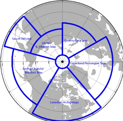
imple-Figure 7. Analysis regions used for the NIC ice edge comparison shown in Tables 1–3.
mented these real-time sources into the daily data stream. In the second hindcast study, rather than assimilating a blended AMSR2+IMS gridded product as was done previously, AMSR2 ice concentration swath data and IMS were im-plemented separately. The initial data assimilation step was based on AMSR2 and SSMIS swath data and the model’s 24 h forecast from the previous day as background for in-put into NCODA. The resulting gridded ice concentration analysis is then blended, using the same technique as de-scribed in Sect. 2.4, with the IMS (interpolated to the model grid) to form the ice concentration field assimilated into CICE. ACNFS uses the direct insertion only near the ice edge scheme described previously. GOFS 3.1 uses a sim-ilar scheme near the ice edge but in addition it uses the analysis+10 % if the model is above this value and analy-sis−10 % if the model is below this value.
An additional ACNFS hindcast and an original GOFS 3.1 hindcast were performed to test the accuracy of assimilating the real-time NAVOCEANO data feed. These ACNFS and GOFS 3.1 hindcasts were integrated from 1 June–31 Au-gust 2014 using the real-time NAVOCEANO feed. As in the earlier test, the same ice edge error analysis was per-formed. Two additional ACNFS simulations were run assim-ilating (1) AMSR2+SSMIS and (2) AMSR2+SSMIS with IMS. These last two hindcasts measure the effect of keeping the current coarser SSMIS as an assimilation data source. The assimilation study for GOFS 3.1 included assimilating (1) AMSR2 with IMS and (2) AMSR2+SSMIS with IMS. All results are shown in Table 3. The regional results are tab-ulated for completeness, but the discussion below focuses on the full Arctic domain.
Figure 8. Daily mean error (km) for the Bering/Chukchi/Beaufort Seas versus time for ACNFS ice edge (define as the 5 % ice con-centration) against the independent ice edge analysis from the NIC over the validation period 1 July 2012–1 July 2013. The blue line shows the use of SSMIS assimilation only, the red line shows the use of AMSR2 assimilation only and the black line shows the use of the blended AMSR2+MASIE assimilation.
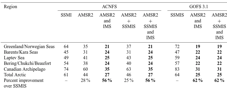
During this 3-month time period, the mean ice edge dis-tance between the ACNFS ice edge using the SSMIS as ini-tialization and the NIC ice edge was 61 km for the full Arctic, compared to 44 km for the ACNFS ice edge initialized us-ing the AMSR2. This results in a 28 % reduction in error by assimilating the higher resolution AMSR2 ice concentration as compared to the SSMIS alone. Assimilating both AMSR2 and SSMIS ice concentrations into ACNFS lowered the mean ice edge error compared to assimilating SSMIS alone (on av-erage 61 to 46 km), an overall improvement of 25 %. The largest reduction in mean ice edge error occurred when the IMS blending technique was assimilated into ACNFS for both AMSR2 and SSMIS. This resulted in a 56 % reduc-tion in ice edge error (on average, 61 to 27 km). Similar to ACNFS, GOFS 3.1 had significant improvement in ice edge location for the entire Arctic (64 km vs. 25 km, 62 %) assim-ilating both the AMSR2 and SSMIS along with the IMS ice concentration products over SSMIS alone.
Table 2. Seasonal mean distance differences (km) between the NIC ice edge and 6 h ACNFS forecasts initialized from various combinations of SSMIS, AMSR2 and IMS data for the time periods January–April and June–September. The bottom row shows the total Arctic percent improvement from each ice forecasting system compared to using SSMIS assimilation alone. The Laptev Sea is fully ice-covered in the winter season and no ice edge analysis was performed. The bold numbers denote the smallest mean distance error between the assimilation test cases.
Region January–April June–September
ACNFS w/ ACNFS w/ ACNFS w/ ACNFS w/ ACNFS w/ ACNFS w/
SSMIS AMSR2 blended SSMIS AMSR2 blended
AMSR2+ AMSR2+
MASIE MASIE
Greenland/Norwegian Seas 33 24 26 46 29 20
Barents/Kara Seas 16 14 13 37 29 19
Laptev Sea – – – 94 78 43
Sea of Okhotsk 33 25 16 62 51 20
Bering/Chukchi/Beaufort 22 16 13 116 84 45
Canadian Archipelago 29 25 22 65 48 36
Total Arctic 29 22 20 75 55 33
Percent improvement – 24 % 32 % – 26 % 55 %
over SSMIS
Table 3. Regional mean distance differences (km) between the NIC ice edge and 6 h ACNFS or 12 h GOFS 3.1 forecasts initialized from various combinations of SSMIS, AMSR2 and IMS data for the time period June–August 2014. The bottom row shows the total Arctic percent improvement from each ice forecasting system compared to using SSMIS assimilation alone. The bold numbers denote the smallest mean distance error between the assimilation test cases.
Region ACNFS GOFS 3.1
SSMI AMSR2 AMSR2 AMSR2 AMSR2 SSMIS AMSR2 AMSR2
and + + and +
IMS SSMIS SSMIS IMS SSMIS
and and
IMS IMS
Greenland/Norwegian Seas 64 35 21 37 21 72 19 19
Barents/Kara Seas 45 31 24 31 24 47 22 22
Laptev Sea 49 41 25 43 25 59 24 24
Bering/Chukchi/Beaufort 54 38 24 40 24 57 22 22
Canadian Archipelago 74 60 35 63 35 83 31 31
Total Arctic 61 44 27 46 27 64 25 25
Percent improvement – 28 % 56 % 25 % 56 % – 62 % 62 %
over SSMIS
4 Conclusions and future plans
Previously, both ACNFS and GOFS 3.1 only assimilated near real-time sea ice concentration derived from SSMIS. SSMIS ice concentration data are available daily and are used to update the initial ice concentration analysis field only near the model ice edge. As the model resolution has increased, the need for higher resolution observational fields has be-come very important. A method of blending ice concentra-tion observaconcentra-tions from AMSR2 and IMS/MASIE has been developed resulting in an ice concentration field with a very high spatial resolution of 4 km. In this study, the blended AMSR2/IMS product was interpolated to the ACNFS and
ACNFS and GOFS 3.1 initialized using both the AMSR2 and SSMIS+IMS/MASIE data sets have substantially lower ice edge errors than the ACNFS and GOFS 3.1 initialized using the coarser SSMIS data. ACNFS initialized using the blended AMSR2+IMS/MASIE product improves the ACNFS pre-dicted ice edge location by 56 %, while GOFS 3.1 showed an improvement of 62 %.
The blended technique described in this paper is the ini-tial methodology for implementing the IMS/MASIE and AMSR2 data products into the operational ice forecast sys-tems. Research is currently underway to develop improved methods to assimilate these new data sources along with other products (i.e., VIIRS ice concentration) that will adjust the ice and ocean fields within the NCODA framework.
This analysis has shown that assimilating a higher hori-zontal resolution, blended AMSR2+IMS/MASIE ice con-centration product yields a more accurate ice edge fore-cast. While including the SSMIS ice concentration field (AMSR2+SSMIS along with IMS/MASIE) did not reduce the ice edge error in ACNFS or GOFS 3.1, it could prove to be beneficial if AMSR2 data become unavailable. For operational forecasting, the current SSMIS ice concentra-tion real-time data source will still be utilized in addiconcentra-tion to the AMSR2 ice concentration and the IMS ice mask for daily use. On 2 February 2015, these two new data sources (AMSR2 and IMS) were added to the operational ACNFS and the pre-operational GOFS 3.1 jobstreams.
Author contributions. All authors contributed substantially to the writing of the manuscript, data analysis and the overall methodol-ogy used to blend the ice concentration and ice mask data sources. D. Hebert was primarily responsible for acquiring and processing the AMSR2 ice concentration data. S. Helfrich was primarily re-sponsible for supplying the project with the IMS ice mask data source. F. Fetterer, S. Stewart and W. Meier were primarily re-sponsible for producing the blended 4 km ice concentration prod-uct. A. Wallcraft and J. Metzger were primarily responsible for im-plementing the blending technique into the operational jobstream. P. Posey and O. M. Smedstad were primarily responsible for inte-grating the hindcasts. M. Phelps and R. Allard were primarily re-sponsible for developing techniques used in the validation of the model results.
Acknowledgements. The numerical hindcasts and forecasts were performed on the Navy DSRC iDataPlex computers at Stennis Space Center, Mississippi, using grants of computer time from the DoD High Performance Computing Modernization Program. We thank both anonymous reviewers and the editor for their comments that significantly helped to improve the quality of this article. Spe-cial thanks to Bruce McKenzie, Charles Perry and Keith Willis for implementing the real-time feed of the AMSR2 and IMS data sources at NAVOCEANO. Thanks also to Bruce Lunde (NAVO-CEANO) for adding the AMSR2 data source into the operational NCODA.
Edited by: L. Kaleschke
References
Beitsch, A., Kaleschke, L., and Kern, S.: Investigating high-resolution AMSR2 sea ice concentrations during the Febru-ary 2013 fracture event in the Beaufort Sea, Remote Sensing, 6, 3841–3856, 2014.
Campbell, W. J., Ramseier, R. O., Zwally, H. J., and Gloersen, P.: Arctic sea ice variations from time-lapse passive microwave im-agery, Bound.-Lay. Meteorol., 13, 99–106, 1980.
Cavalieri, D. J., Burns, B. A., and Onstott, R. G.: Investigation of the effects of summer melt on the calculation of sea ice concentration using active and passive microwave data, J. Geophys. Res., 95, 5359–5369, 1990.
Comiso, J. C. and Nishio, F.: Trends in the sea ice cover using en-hanced and compatible AMSR-E, SSMI/S, and SMMR data, J. Geophys. Res., 113, C02S07, doi:10.1029/2007JC004257, 2008. Cummings, J. A. and Smedstad, O. M.: Ocean data impacts in global HYCOM, J. Atmos. Ocean. Tech., 31, 1771–1791, doi:10.1175/JTECH-D-14-00011.1, 2014.
Fetterer, F., Knowles, K., Meier, W., and Savoie, M.: Updated daily, Sea Ice Index, National Snow and Ice Data Center, Boulder, Col-orado, USA, http://dx.doi.org/10.7265/N5QJ7F7W (last access: 17 August 2015), 2002.
Fetterer, F., Stewart, J. S., and Meier, W. N.: MASAM2: Daily 4-Km Arctic Sea Ice Concentration, 2012–2014, National Snow and Ice Data Center, Boulder, Colorado, USA, doi:10.7265/N5ZS2TFT, 2015.
Gloersen, P., Zwally, H. J., Chang, A. T. C., Hall, D. K., Campbell, W. J., and Ramseier, R. O.: Time-dependences of sea ice concen-tration and multiyear ice fraction in the Arctic Basin, Bound.-Lay. Meteorol., 13, 339–360, 1978.
Helfrich, S. R., McNamara, D., Ramsay, B. H., Baldwin, T., and Kasheta, T.: Enhancements to, and forthcoming developments in the Interactive Multisensor Snow and Ice Mapping System (IMS), Hydrol. Process., 21, 1576–1586, 2007.
Hunke, E. C. and Lipscomb, W.: CICE: The Los Alamos sea ice model, documentation and software user’s manual, ver-sion 4.0, Tech. Rep. LA-CC-06-012, Los Alamos National Lab-oratory, Los Alamos, NM, http://oceans11.lanl.gov/svn/CICE/ tags/release-4.0/doc/, last access: 17 August 2015, 2008. Imaoka, K., Kachi, M., Kasahara, M., Ito, N., Nakagawa, K., and
Oki, T.: Instrument performance and calibration of AMSR-E and AMSR2, Int’l Archives of the Photogrammetry, Remote Sensing and Spatial Information Science, vol. 38, part 8, Kyoto, Japan, 2010.
Kunkee, D. B., Poe, G. A., Boucher, D. J., Swadley, S. D., Hong, Y., Wessel, J. E., and Uliana, E. A.: Design and evaluation of the first Special Sensor Microwave Imager/Sounder, IEEE T. Geosci. Remote, 46, 863–883, 2008.
Markus, T. and Cavalieri, D. J.: An enhancement of the NASA Team sea ice algorithm, IEEE T. Geosci. Remote, 38, 1387– 1398, doi:10.1109/36.843033, 2000.
on biology and human activity, Rev. Geophys., 52, 185–217, doi:10.1002/2013RG000431, 2014.
Meier, W. N., Fetterer, F., Stewart, J. S., and Helfrich, S.: How do sea ice concentrations from operational data compare with passive microwave estimates?, Ann. Glaciol., 56, 332–340, doi:10.3189/2015AoG69A694, 2015.
Metzger, E. J., Posey, P. G., Thoppil, P. G., Townsend, T. L., Wall-craft, A. J., Smedstad, O. M., Franklin, D. S., Zamudio, L., and Phelps, M. W.: Validation test report for the global ocean prediction system V3.1 – 1/12◦HYCOM/NCODA/CICE/ISOP, Naval Report NRL/MR/7320-15-9579, Stennis Space Center, MS, 2015.
NIC – National Ice Center: IMS daily northern hemisphere snow and ice analysis at 1 km, 4 km and 24 km resolution, Na-tional Snow and Ice Data Center, Boulder, Colorado, USA, doi:10.7265/N52R3PMC, 2008.
NIC – National Ice Center – and NSIDC: Multisensor Ana-lyzed Sea Ice Extent-Northern Hemisphere, developed by: Fet-terer, F., Savoie, M., Helfrich, S., and Clemente-Colon, P., Na-tional Snow and Ice Data Center, Boulder, Colorado, USA, doi:10.7265/N5GT5K3K, 2010.
NSIDC – National Snow and Ice Data Center: https://nsidc. org/news/newsroom/20121002MinimumPR.html, press release 2 October 2012.
Perovich, D., Gerland, S., Hendricks, S., Meier, W., Nicolaus, M., and Tschudi, M.: Sea Ice, in: Arctic Report Card 2014, http:// www.arctic.noaa.gov/reportcard (last access: 17 August 2015), 2014.
Posey, P. G., Metzger, E. J., Wallcraft, A. J., Preller, R. H., Smedstad, O. M., and Phelps, M. W.: Validation of the 1/12◦ Arctic Cap Nowcast/Forecast System (ACNFS), Naval Report NRL/MR/7320-10-9287, Stennis Space Center, MS, available at: http://www7320.nrlssc.navy.mil/pubs (last access: 17 August 2015), 2010.
Posey, P. G., Hebert, D., Metzger, E. J., Wallcraft, A. J., Cummings, J. A., Preller, R. H., Smedstad, O. M., and Phelps, M. W.: Real-time assimilation of satellite derived ice concentration into the Arctic Cap Nowcast/Forecast System, Conference Proceedings, Oceans 2011 MTS/IEEE, Hawaii, available at: http://www7320. nrlssc.navy.mil/pubs (last access: 17 August 2015), 2011. US Department of the Navy: U.S. Navy Arctic Roadmap 2014–