e-ISSN: 2278-067X, p-ISSN: 2278-800X, www.ijerd.com
Volume 14, Issue 1 (January 2018), PP.59-63
Dynamic Behaviour of Asynchronous Generator In Stand-Alone
Mode Under Load Perturbation Using MATLAB/SIMULINK
Mrs.Anindita Das Mondal
Brainware Group of Institutions-SDET
Corresponding Author:Mrs.Anindita Das Mondal
ABSTRACT:-
The world's conventional resources will be depleted in few hundred years. To avoid energy crisis, uses of renewable energy resources are increasing day by day. A Asynchronous generator with stand-alone mode is the better option to produce electricity in varying speed in wind turbines. This paper deals with the dynamic behavior of Asynchronous Generator operated in stand-alone mode under load perturbation.Keywords:-
Stand-alone mode, wind turbine, asynchronous generator, capacitor bank--- Date of Submission: 05 -01-2018 Date of acceptance: 30-01-2018 ---
I.
INTRODUCTION
To avoid energy crisis in future if we use renewable energy resources such as solar, wind, wave etc. then our daily energy demand can be met. Recent trend for power generation is to use renewable resources. In wind turbines, asynchronous generators are often used in stand-alone mode to generate electricity. Asynchronous generators have some advantages over conventional synchronous generators. Usually, the major limitation of a Asynchronous Generator is that it requires reactive power from the supply for the excitation process. The asynchronous generator operation in stand-alone mode is essential to supply far districts where electrical grid extension is not economically feasible. Asynchronous generator is connected by appropriate capacitor bank across its terminals to make it self-excited. This paper gives an approach to model dynamic behavior of such generator during load perturbations. For the first time in 1935 when Basset and Potter [1] suggested that the induction machine can be operated an induction generator in isolated mode by external capacitor. They summarized that the induction machine with capacitive excitation can be build up and the final value being determined by the saturation curve of the machine. E. Muljadi et al. [2] in his paper investigate the wind turbine application in Selfexcited Induction Generators. Sutanto et al. [3] in his paper proposed that the transient behaviour of a three phase SEIG supplying a symmetrical load. They presented an approach to model performance of induction generators to maintain constant terminal voltage under resistive and reactive loads. They explained a modified and analytical method for determining the range of capacitive VAR requirements for maintaining a constant flux and for obtaining performance with a desired level of voltage regulation. The analysis used the steady state equivalent circuit to predict the performance of the generator. Doxey [4] in his paper concluded that the basic requirement for the induction motor work as self-excited induction generator is the leading current of correct magnitude.
A. Mathematical Modeling of Asynchronous Generator:
The modeling of the three phase asynchronous generator is developed by using a stationary d-q axes reference frame and the relevant voltage-current equations are
= + p +
(1) From which, the current derivative can be expressed as:
= (2)
Where, , , , and are defined in Appendix The developed electromagnetic torque ( ) is as
= (3P/4) (3)
The electromagnetic torque balance equation is as
= J(2/P) + (4)
Where is the input torque i.e. transmitted to the shaft of the generator from prime mover (typically wind
turbine) and is also can be expressed by,
= a - b (5)
The values of „a‟ and „b‟ for the under test are given in Appendix . The derivative of the rotor speed from equation is as
= (6)
The generator operates in the saturation region and it magnetization characteristic is non-linear in nature. Hence the magnetization current ( ) should be calculated in every step of integration is terms of stator and rotor current as
(7)
Three-phase currents are obtained by converting direct and quadrature axes components into a, b, c phase currents as follows:
=
(8)
(9)
(10)
…….[5][6]
II.
SIMULINK MODEL
III.
RESULT AND DISCUSSION
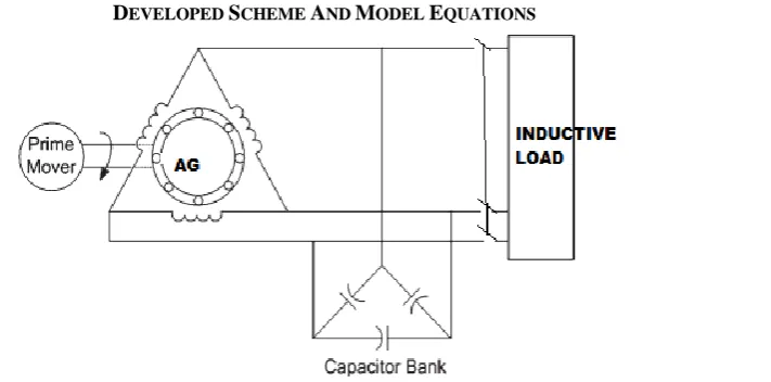
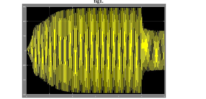
Since the studied Asynchronous Generator in stand-alone mode must be excited by a fixed capacitor bank with 50µF/phase is used to supply the required reactive. A three-phase balanced inductive load is taken for this simulation. For the loading condition, a sudden change is observed in the output terminal of asynchronous generator self-excited mode. As a result the changes in phase voltage and phase current obtained after t=5sec in
Fig.2 output current after applying load at t=5sec
Now we withdraw the load at t=5sec and suddenly terminal gets short circuited.
Fig.3 Output current during short circuit condition at t=5sec
Fig4. Output voltage during short circuit condition at t=5 sec
IV.
CONCLUSION
Dynamic models are developed using d-q axes stationary reference frame for determining transient response condition. The developed model is tested by simulating the dynamic behaviour during load perturbation. Voltage drop with inductive load occurs as expected. The dynamic behaviour plays a vital role to predict the operation of asynchronous generator in stand-alone mode to obtain better performance. The analysis and results presented in this paper prepare a foundation for employing the asynchronous generator in a numerous scope for further research and experimentation in the field of renewable energy.
REFERENCES
[1]. E.D Basset, F. M. Potter , “Capacitive excitation for induction generators” , AIEE Trans. (Electrical Engineering), Vol. 54. pp.540-545, March 1935.
[2]. E. Muljadi, J. Sallan, M. Sanz and C. P. Butterfield, “Investigation of Selfexcited Induction Generators for Wind Turbine Applications,” in Thirty- Fourth Industry Applications Conference Annual Meeting, Phoenix, October 1999.
[4]. B.C. Doxey, “Theory and application of the capacitor self -excited induction generators” the engineer, Nov.29,1963.
[5]. B.Singh, S.S Murthy, S.Gupta, “Analysis and design of STATCOM based voltage regulator for self-excited induction generator feeding non linear loads”, IEEE Trans. on energy Convers.,vol.53, no.5,pp.1437-1452,Oct. 2006.
[6]. Bhim Singh, S. S. Murthy, Sushma Gupta,” (september/october 2005): Transient Analysis of Self-Excited Induction Generator With Electronic Load Controller (ELC) Supplying Static and Dynamic Loads “‟ IEEE trans. on industry applications, vol. 41, no. 5.
[7]. Journal of Emerging Trends in Engineering and Applied Sciences (JETEAS) 3 (4): 729-733 © Scholarlink Research Institute Journals, 2012 (ISSN: 2141-7016)
[8]. P. K. Sen and J. P. Nelson, “Application Guidelines for InductionGenerators,” in IEEE International Conference on Electric Machines and Drives, Milwaukee, May 1997.
[9]. B. Palle, M. G. Simoes and F. A. Farret, “Dynamic Simulation and Analysis of Parallel Self-excited Induction Generators for Islanded Wind Farm Systems,” IEEE Transactions on Industry Applications, vol. 41, no. 4, pp. 1099 - 1106 , July 2005.
[10]. Guiliani Scherer, Lucas; Figueiredo de Camargo, Robinson,”(2011): Advances in modeling and control of micro hydropower stations with induction generators”, Energy Conversion Congress and Exposition (ECCE), 2011 IEEE, pp: 997 – 1004.
V.
APPENDIX
Parameters of 2.2 kW, 230 V, 50 Hz,7.8 A, 4-pole, 3-ph squirrel cage asynchronous generator is operated at stand-alone mode. The parameters are as follows:
P = 4;
Lls = 0.0142H/14.2mH; Llr = 0.0142H/14.2mH; Rs = 2.88Ω;
Rr = 2.88Ω; C = 0.00005F/50µF; J = 0.0842kg/sq. m; a = 249.39;
b = 0.7875;
Lm = 0.3177 (for Im ≤ 0.75)
= 0.3502 - 0.0349 Im + 0.0017 Im2
(for 0.75 < Im ≤ 4.25)
= 0.17677 (for Im > 4.25)
…...[5][6]