MULTI-INPUT DC-DC CONVERTER FOR PV
SINGLE PHASE POWER GENERATING SYSTEM
Department of Electrical Engineering
A R T I C L E I N F O
INTRODUCTION
With the increase in price of fossil fuel and decrease in production cost of renewable energy components, the difference between cost per kWh unit of electricity generated from these sources is decreasing gradually. Most of the countries are motivated to generate electricity from renewable energy sources due to climate change and energy security. But renewable sources such as solar energy and wind energy are intermittent in nature and thus the problem is to supply constant power to the loads.
International Journal of Current Advanced Research
ISSN: O: 2319-6475, ISSN: P: 2319 –
Available Online at www.journalijcar.org
Volume 6; Issue 5; May 2017; Page No.
DOI: http://dx.doi.org/10.24327/ijcar.2017.
Article History:
Received 5th February, 2017
Received in revised form 2ndMarch, 2017
Accepted 8th April, 2017
Published online 28th May, 2017
Copyright©2017 Rohan R. Pote and Dipti D. Patil
which permits unrestricted use, distribution, and reproduction in any medium, provided the original work is properly cited.
Key words:
Hybrid System; Renewable Energy Sources; Solar Energy; Wind Energy; Multi Input Converter; Dc-Dc Converter; Microgrid; Isolated System; Grid Connected System
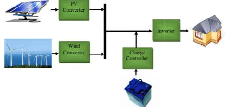
Fig 1 Existing Solar PV-Wind Hybrid System
*Corresponding author: Rohan R. Pote
Department of Electrical Engineering, A.C.Patil College of Engineering, Kharghar, Navi Mumbai, University of Mumbai, India
DC CONVERTER FOR PV-WIND-BATTERY BASED GRID CONNECTED
SINGLE PHASE POWER GENERATING SYSTEM
Rohan R. Pote* and Dipti D. Patil
Department of Electrical Engineering, A.C.Patil College of Engineering, Kharghar, Navi Mumbai University of Mumbai, India
A B S T R A C T
The conventional approach for the integration of multiple renewable sources and energy storage elements involves using dedicated single-input converters for each source and requires more number of converter stages leading to considerable reduction in relia and efficiency of the system. In order to address this issue, a power
control strategy of a PV-wind-battery based grid connected single phase power generating system with an efficient multi-input dc-dc converter is proposed. This syste
load, maintain the power flow between different sources, inject surplus power into the grid and charge the battery as and when required. A bidirectional buck
for harnessing power from PV source with battery charging/disc
transformer coupled boost half-bridge converter is used for harnessing power from wind source. A single-phase full-bridge inverter is used for feeding ac loads and interaction with grid. The proposed converter configuration has reduced number of power conversion stages with less component count, and reduced losses compared to existing grid
systems. This improves the efficiency and reliability of the system. Simulation studies using MATLAB/Simulink are carried out to verify the viability of the proposed system under various modes of operation depending on availability of sources and change in load.
With the increase in price of fossil fuel and decrease in production cost of renewable energy components, the difference between cost per kWh unit of electricity generated decreasing gradually. Most of the countries are motivated to generate electricity from renewable energy sources due to climate change and energy security. But energy and wind energy are roblem is to supply
This problem can be tackled by integrating battery and grid. Due to the complementary behaviour of solar and wind energy, PV-wind hybrid systems are perfectly capable of generating energy in any season.
Microgrid is a localized grouping of electricity sources and loads that normally operates connected to and synchronous with the traditional centralized electrical grid (macrogrid), but can disconnect and function autonomously as physical and/or economic conditions dictate. Modern microgrids take in energy from a variety of sources
and a main electrical grid and facilitate not only its conversion into electrical energy, but also the demand management, storage, and generation associated with the output of the system. This project focuses on the desi
main grid connected microgrid that is supplied primarily by photovoltaic (PV) panels and a wind turbine, but which also has the capability to work in isolated mode.
The Solar photovoltaic (PV) and wind are everlasting, clean, abundant, free, modular and secure, sources of energy which have potential to replace all existing conventional sources of energy. The existing system with two renewable energy sources- PV-wind with battery and load is shown in fig. 1. Such systems require dedicated single
each source which further increases no of converters. The low output voltage of PV-wind needs multiple power conversion
International Journal of Current Advanced Research
– 6505, Impact Factor: SJIF: 5.995
www.journalijcar.org
2017; Page No. 3860-3866
http://dx.doi.org/10.24327/ijcar.2017.3866.0383
Rohan R. Pote and Dipti D. Patil. This is an open access article distributed under the Creative Commons Attribution License, which permits unrestricted use, distribution, and reproduction in any medium, provided the original work is properly cited.
Wind Hybrid System
A.C.Patil College of University of
BATTERY BASED GRID CONNECTED
A.C.Patil College of Engineering, Kharghar, Navi Mumbai,
The conventional approach for the integration of multiple renewable sources and energy input converters for each source and requires more number of converter stages leading to considerable reduction in reliability and efficiency of the system. In order to address this issue, a power flow management battery based grid connected single phase power generating dc converter is proposed. This system can supply flow between different sources, inject surplus power into the grid and charge the battery as and when required. A bidirectional buck-boost converter is used for harnessing power from PV source with battery charging/discharging control, while a bridge converter is used for harnessing power from wind bridge inverter is used for feeding ac loads and interaction with uced number of power conversion stages with less component count, and reduced losses compared to existing grid-connected hybrid ficiency and reliability of the system. Simulation studies verify the viability of the proposed system under various modes of operation depending on availability of sources and change in load.
tackled by integrating battery and grid. Due to the complementary behaviour of solar and wind wind hybrid systems are perfectly capable of generating energy in any season.
Microgrid is a localized grouping of electricity sources and normally operates connected to and synchronous with the traditional centralized electrical grid (macrogrid), but can disconnect and function autonomously as physical and/or economic conditions dictate. Modern microgrids take in urces-in this case, sunlight, wind, and a main electrical grid and facilitate not only its conversion into electrical energy, but also the demand management, storage, and generation associated with the output of the system. This project focuses on the design and simulation of a main grid connected microgrid that is supplied primarily by photovoltaic (PV) panels and a wind turbine, but which also has the capability to work in isolated mode.
The Solar photovoltaic (PV) and wind are everlasting, clean, nt, free, modular and secure, sources of energy which have potential to replace all existing conventional sources of energy. The existing system with two renewable energy wind with battery and load is shown in fig. 1. ated single-input converters for each source which further increases no of converters. The low wind needs multiple power conversion
Research Article
stages for boosting to the required level of voltage at load which reduces efficiency and reliability of the system. Such systems have limitation of unregulated battery charging-discharging. In literature, the solution to this problem is to use higher PV-battery voltage level which further rises another complications of design implementation and safety of the personnel and equipment. The use of dedicated single-input converters one for each source increase the cost as the high numbers of switching devices are required. Also size and volume of such conventional system is comparatively more.
The proposed system has two renewable power sources (Solar PV and wind), load, grid, and battery. Hence, a power flow management system is essential to balance the power flow among all these sources. The main objectives of this system are as follows.
to supply continuous power to the load.
to evacuate excess power from the renewable sources to the grid.
to explore a multi objective control scheme for optimal power flow control.
The integration of solar and wind energy due to their complementary nature as a hybrid energy generating system have emerged as best renewable energy source combination. In [1], [2], the modeling aspects of stand-alone hybrid power system and control strategy are discussed. Dynamic performance of a standalone PV–wind system with battery storage is analyzed in [2]. PV–wind hybrid generation of electricity and integration of the power grid are the important research areas. Chen et al. [3], [4] have proposed a grid-connected hybrid PV/wind power system which has a multi-input dc–dc converter and a full-bridge dc–ac inverter.
The steady-state performance of a grid-connected hybrid PV-wind-battery based system is analyzed in [5] which focuses on system engineering which contains unit sizing, cost analysis, energy production, and reliability of the system. Battery and both sources are connected to the dc link through dedicated single input converters and this dc link is connected to the main grid through an inverter. The multi-input converter for hybrid power systems is used because of less component count, centralized control, compactness, and more power density. In partially isolated multiport topologies [6]-[9], some of the ports have a common ground, these power ports are isolated from the remaining ports for matching port voltage levels. The basic philosophy and preliminary study of a compact and low-cost multi-input transformer-coupled dc– dc converter capable of interfacing multiple sources for a stand-alone application is presented in [10]. In [11], the integration of renewable sources to the grid, detailed analysis, exhaustive simulation have been included.
The organization of this paper is as follows: In section II, the block diagram, the power circuit configuration with principle of operation of the proposed system is described. Control scheme for power flow management of the proposed system are explained in section III. In section IV, the working of proposed system is verified by simulating on MATLAB/Simulink platform.
PROPOSED METHODOLOGY
The proposed converter configuration and control scheme for power flow management have capability to control power
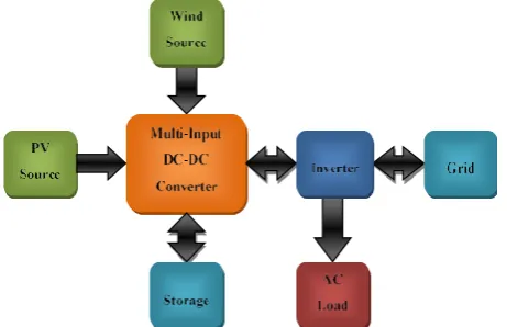
Block Diagram
The block diagram of proposed system which contains four power sources (PV, wind, battery, grid) and three power sinks (Load, battery, grid) is shown in fig. 2. A multi-input DC-DC converter is used to interconnect these sources. The function of this converter is to provide constant power to the inverter with voltage boosting. The functions of the inverter are - power conversion from dc to ac, providing constant supply to load and interaction with grid.
The surplus power generated from PV-wind source is injected to the grid. When these renewable sources are not present, the required power is fed from the grid to the load. This system can work either in stand-alone or in grid-connected modes. This system is suitable for household application where simple, low cost, compact topology with centralized control that can work autonomously is desired.
Proposed Converter Configuration
The schematic circuit diagram of proposed converter is depicted in fig. 3. The red part of the circuit is single phase full bridge inverter with filter, load and grid. The black part is the main dc link and the blue part is the proposed multi-input dc-dc converter. This multi-input dc-dc converter contains bidirectional buck-boost converter and transformer coupled boost dual half bridge converter. The bidirectional buck-boost converter is used for harnessing power from solar PV with battery charging/discharging control. The functions of this converter are MPP tracking of PV source, battery charging/discharging control and the voltage boosting. The PV array with the battery is used for inherent voltage boosting to the required voltage level. The output of the bidirectional buck-boost converter is given to the transformer coupled boost dual half bridge converter.
The half bridge boost converter is used for harnessing power from the wind. This half bridge converter contains a high frequency step up transformer which reduced the size of the system because of high frequency. The boosting capability is also enhanced further due to the step up transformer. Also, the galvanic isolation between the input sources and the load. This high frequency transformer contains dc links on both sides of the winding. Controlling the voltage across one of the dc link ensures voltage control of another side dc link. This makes the control strategy simple. So, by controlling the voltage across dc ink C1-C2 controls the voltage across dc link C3-C4.
The voltage across the dc link (Vdc) is maintained constant with the help of multi input dc-dc converter, so that the input voltage to the inverter will be constant and eventually voltage across the load will be maintained constant. The single phase full bridge inverter is connected to the load as well as the grid. The filter is used to remove distortions. The proposed converter has reduced number of power conversion stages with less component count and high efficiency compared with the existing grid-connected schemes. The topology requires only six power switches.
Principle of Operation
The working of the proposed converter configuration depends upon the availability of the sources and change in load. The primary side dc link can be directly controlled by half-bridge boost converter or by bidirectional buck-boost converter. The output of the bidirectional buck-boost converter is given to the transformer coupled half bridge converter. The output of the complete multi input dc-dc converter is controlled by controlling the voltage across the dc link C1-C2 and the voltage across the C1-C2 is controlled by switches T3-T4.
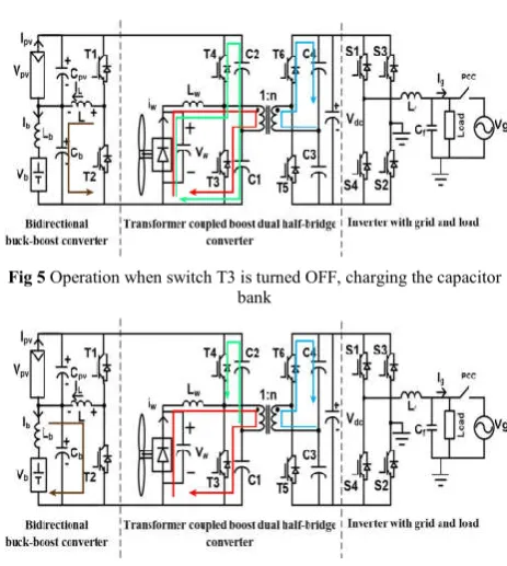
When switch T3 is turned ON, the wind energy is transferred to the inductor and the current flowing through the source inductor increases. The capacitor C1 discharges through the transformer primary and switch T3, as shown in fig. 4. In the secondary side, capacitor C3 charges through transformer secondary and antiparallel diode across switch T5.
When switch T3 is turned OFF, initially, the inductor current flows through antiparallel diode of switch T4 and through the capacitor bank C1-C2, charging the capacitor bank as shown in fig. 5. During this interval, the current flowing through diode decreases and that flowing through transformer primary increases. As the current flowing through antiparallel diode charges the capacitor bank, the reverse voltage across the diode increases and the diode turns OFF. At the same time, the current flowing through the inductor becomes equal to that flowing through transformer primary.
Since, T4 is gated ON during this time, capacitor C2 discharges through transformer primary and switch T4. On the secondary side, Capacitor C4 charges through transformer
secondary and antiparallel diode of switch T6 as shown in fig. 6.
In the proposed configuration, as shown in fig. 4, the working proposed converter depends upon availability of sources and required load, therefore the working of bidirectional buck-boost converter changes accordingly. When required load is less than available renewable energy, the bidirectional buck-boost converter works in battery charging mode. During battery-charging mode, L is positive. When switch T1 is turned ON, the energy in PV source is transferred to the inductor, the energy in inductor increases. This energy in inductor is transferred to the battery, charging the battery. So, the energy in inductor decreases.
When required load is more than available renewable energy, the bidirectional buck-boost converter works in battery discharging mode. In battery discharging mode, the L is negative. When T2 is turned ON, the energy in battery is transferred to the inductor, discharging the battery. The energy in inductor increases. This energy in inductor is transferred to the capacitor across PV source. The energy in inductor decreases. It can be proved that Vb=Vpv [D/(1-D)].
POWER FLOW MANAGEMENT CONTROL
STRATEGY
The proposed system contains four power sources (PV, wind, battery and grid) and three power sinks (load, battery and grid). Therefore, a reliable power flow management control strategy is required to maintain power flow among these sources. The control philosophy for power flow management of this system is based on the power balance principle. Its control strategy is shown in fig. 7.
In bidirectional buck-boost converter control, the MPPT and non-MPPT mode is selected by availability of the PV source. If the PV source is present, Vpvref is set to MPP value of solar PV, so that it will extract maximum power from PV source. An incremental conductance method is used for MPP tracking (MPPT). If PV source is absent, Vpvref is set such Fig 3 Schematic Circuit Diagram
Fig 4 Operation when switch T3 is turned ON
Fig 5 Operation when switch T3 is turned OFF, charging the capacitor bank
that it will maintain dc link voltage at 400V that ensures constant supply to the load even though PV is absent.
The PI controller is used to reduce the error between set value and actual value. From KCL, the relationship between the average value of inductor, PV, and battery current over a switching cycle is given by IL = Ib + Ipv. So by controlling the inductor current, battery current and PV current is controlled. Therefore, the MPP operation is controlled by controlling IL while maintaining a proper battery charge level. IL is used as inner loop control parameter for faster dynamic response while for outer loop, capacitor voltage across PV source is used for ensuring MPP voltage. The output of PI controller is compared with triangular wave to get PWM switching pulses for Power switches of bidirectional buck-boost converter. In half bridge converter control, the MPPT and non-MPPT mode is selected by availability of the Wind source. If the wind source is present, Iwref is set to MPP value of wind. The PI controller is used to reduce the error between set value and actual value.
If wind source is absent, the control switch will give output as half. The half duty cycle of the power switches of half bridge converter ensures the transfer of the power from PV and battery to the transformer.
In single phase full bridge inverter control, VLoadref is set at preferred value which is to be maintained across the load. For stability purpose inverter should be synchronized with grid. The grid voltage is used for synchronizing reference voltage by using PLL method. The αβ-dq conversion is used for VLoad and VLoadref to obtain Vd-Vq reference and actual values from which errors are fed to the PI controllers to reduce the error. The values obtained from PI controllers are again converted to αβ which is used for generating Iinvref. The error obtained from Iinvref and Iinv is fed to the PI controller. The generated signal derived from PI controller is used for generating switching pulses of inverter switches.
The proposed system has the following advantages.
Only six power switches are required for MPPT of both the sources, voltage boosting and battery charging/discharging control.
The use of high frequency transformer is to reduce size of the system and improve voltage boosting.
The enhancement in voltage boosting due to PV with battery and further increased by step up transformer.
Transformer is providing galvanic isolation between renewable sources with battery and the load.
This converter configuration can operate in different modes of operation based availability of the sources and the load requirement.
Battery charging efficiency is enhanced due to only one converter is present between PV source and battery.
Utilization of the system is more as a single multi-input dc-dc converter is used with only six power switches. Also the cost of the system is less.
SIMULATION ANALYSIS AND RESULTS
Fig 7 Proposed power flow management control strategy of a grid-connected hybrid PV–wind-battery based system.
The proposed converter configuration and the control scheme of power flow management are verified by simulating on MATLAB/Simulink platform. The results are obtained for different modes of operation depend on the availability of the power sources and change in load.
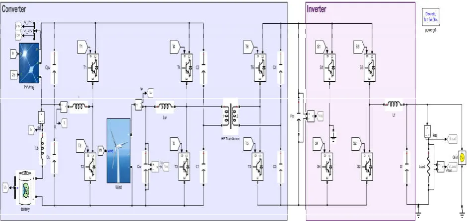
MATLAB Simulation
The MATLAB simulation model of the proposed bidirectional multi-input converter consists of PV solar array, wind source, battery, high frequency transformer and six power switches. The MATLAB simulation model of proposed converter configuration is shown in fig. 8. This converter connected to a single phase full bridge inverter through dc link. This converter is used for maintaining dc link voltage at 400 V. The dc voltage is then converted to ac voltage through the inverter. The filter is used for eliminating distortion of the inverter output. The filtered output of the inverter is given to the load and grid. The voltage and current across the load are maintained constant and continuous irrespective of the availability of sources. The remaining power after feeding to the load is injected into the grid.
The four sources and three sinks make the control scheme more crucial to maintain the power flow among them efficiently along with the MPP tracking and the battery charging/discharging control.
This control strategy is able to utilize all six power switches of the converter to maintain constant 400 V across the DC link. Also, the MPP tracking of both the sources as well as battery charging/discharging control achieved through this converter. The constant voltage across the load is maintained by controlling the switches.
RESULTS
The simulation of the proposed system is tested at different conditions based on availability and change in the sources to verify the power flow management. The following different modes of operation depend on change in load and availability of sources.
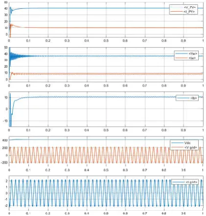
Steady-State Operation in the MPPT Mode when Both Sources Present
The steady-state response of the system during the MPPT mode of operation when both sources are present is shown in fig. 9. The values of PV and wind sources are set to their MPP values. The PV quantities Vpv and Ipv and wind quantities Vw and Iw attain set values required for MPP operation. The voltage across the main dc-link is maintained constant with the help of dc-dc converter. The battery charged with the constant magnitude of current, and the remaining power is fed to the grid.
Decrease in the Load while Operating in the MPPT Mode when Both Sources Present
The system response for decrease in the load while operating in the MPPT mode when both sources present is shown in fig. 10. The values for PV and wind sources attain their MPP values required for MPP operation. As the load is decreased, the extra power remaining after supplying the load is injected to the grid. The increase in grid current implies the extra current being fed to the grid.
Response of the System in the Absence of PV Source, while Wind Source Continues to Operate at MPPT
The response of the system in the absence of PV source is shown in fig. 11. Even though the PV source is absent, the Vpv is maintained with capacitor across PV source to maintain 400 V across dc link. The wind source is maintained at their MPP value. In this case, the battery is charged at low magnitude to provide required amount of power supply to the load.
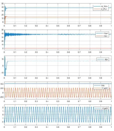
Response of the System in the Absence of Wind Source, while PV Source Continues to Operate at MPPT
The response of the system in the absence of wind source is shown in fig, 12. Even though the wind source is absent, the Vw is maintained with capacitor across wind source to maintain 400 V across dc link. The PV source is maintained at their MPP value. In this case, the excess power after supplying to the load is injected to the grid.
Fig 9 Steady-state operation in the MPPT mode when both sources present
Response of the System in the Absence of Both the Sources
Response of the system in the absence of both the sources (PV and wind source) is shown in fig. 13. In absence of both the sources, the required power is supplied from battery and grid. The dc link voltage is maintained at 400 V by maintaining the Vpv and Vw at their respective values. The battery is discharging to supply the required power to the load.
Response of the System in the Absence of Grid
Response of the system in the absence of grid is shown in fig. 14. In isolated condition, the required power is supplied from renewable sources and battery. The dc link voltage is maintained at 400 V by maintaining the Vpv and Vw at their respective MPP values. Since grid is absent, the grid current and voltage are zero.
In all the above cases which are based on availability of sources and change in load, the constant voltage is being fed to the load in any circumstances and then excess/requisite power is injected/taken from the grid respectively.
Fig 11 Response of the system in the absence of PV source, while wind source continues to operate at MPPT
Fig 12 Response of the system in the absence of wind source, while PV source continues to operate at MPPT
Fig 13 Response of the system in the absence of both the sources
CONCLUSION AND FUTURE SCOPE
The problem of intermittent nature of renewable sources and hence the problem to get continuous uninterruptable supply can be tackled by using complementary nature of PV-wind sources with integration of storage and grid to our benefit. A multi-input DC-DC converter for PV-wind-battery based grid connected single-phase power generating system with power flow management scheme for household application is proposed. The proposed hybrid system integrated with PV and wind source can extract maximum energy from the two sources. This can be done by a multi-input dc–dc converter with a single phase full-bridge inverter. The proposed system can operate either in grid connected or in stand-alone modes. Therefore, this system is applicable from the remote areas to the advanced areas. The simulation results prove that the control strategy can work for any condition of source availability and change in load.
A multiobjective control strategy which is capable of improved utilization of both renewable sources with battery, and power flow management in a PV-wind-battery based hybrid grid connected single phase power generating system feeding ac loads is presented. The existing system requires dedicated single input converter for each source, while proposed system requires only single converter. This multifunction converter is used for MPP tracking, battery charge/discharge control and voltage boosting. The conventional hybrid system requires multiple conversion stages, therefore losses are more and efficiency is less. This system on the other hand is more efficient and reliable. The number of power switches used in this system is only six that cuts down the cost. The high frequency transformer is used along with less no of power switches which eventually reduces the size of the system. The MATLAB simulation is done to verify feasibility of the proposed system. This model is tested on different condition to verify the practicability of the control strategy. The proposed system is can supply continuous power to the load and feed extra power to the grid. This system is perfect for household application where a simple, low cost, compact topology is required capable of autonomous operation with or without grid connectivity.
References
1. Borowy, Bogdan S., and Ziyad M. Salameh. "Dynamic response of a stand-alone wind energy conversion system with battery energy storage to a wind gust."IEEE Transactions On energy conversion12.1 (1997): 73-78.
2. Chen, Cheng-Wei, Kun-Hung Chen, and Yaow-Ming Chen. "A semi-isolated multi-input converter for hybrid PV/wind power charger system."Power Electronics Conference (IPEC-Hiroshima 2014-ECCE-ASIA), 2014 International. IEEE, 2014.
3. Chen, Yaow-Ming, Chung-Sheng Cheng, and Hsu-Chin Wu. "Grid-connected hybrid PV/wind power generation system with improved DC bus voltage regulation strategy."Applied Power Electronics Conference and Exposition, 2006. APEC'06. Twenty-First Annual IEEE. IEEE, 2006.
4. Chen, Yaow-Ming, et al. "Multi-input inverter for grid-connected hybrid PV/wind power system."IEEE transactions on power electronics22.3 (2007): 1070-1077.
5. Giraud, Francois, and Zyiad M. Salameh. "Steady-state performance of a grid-connected rooftop hybrid wind-photovoltaic power system with battery storage."IEEE transactions on energy conversion16.1 (2001): 1-7. 6. Al-Atrash, Hussam, Feng Tian, and Issa Batarseh.
"Tri-modal half-bridge converter topology for three-port interface."IEEE Transactions on Power Electronics22.1 (2007): 341-345.
7. Qian, Zhijun, et al. "Modeling and control of three-port DC/DC converter interface for satellite applications."IEEE Trans. Power Electron25.3 (2010): 637-649.
8. Li, Wuhua, et al. "Decoupling-controlled triport composited DC/DC converter for multiple energy interface."IEEE Transactions on Industrial Electronics62.7 (2015): 4504-4513.
9. Xu, Chi, et al. "Performance analysis of coupled inductor based multiple-input DC/DC converter with PWM plus phase-shift (PPS) control strategy."ECCE Asia Downunder (ECCE Asia), 2013 IEEE. IEEE, 2013.
10. Mangu, B., and B. G. Fernandes. "Multi-input transformer coupled DC-DC converter for PV-wind based stand-alone single-phase power generating system."Energy Conversion Congress and Exposition (ECCE), 2014 IEEE. IEEE, 2014.
11. Mangu, B., et al. "Grid-Connected PV-Wind-Battery-Based Multi-Input Transformer-Coupled Bidirectional DC-DC Converter for Household Applications."IEEE Journal of Emerging and Selected Topics in Power Electronics4.3 (2016): 1086-1095.
How to cite this article:
Rohan R. Pote and Dipti D. Patil (2017) 'Multi-Input Dc-Dc Converter For Pv-Wind-Battery Based Grid Connected Single Phase Power Generating System', International Journal of Current Advanced Research, 06(05), pp. 3860-3866.
DOI: http://dx.doi.org/10.24327/ijcar.2017.3866.0383