IJIRT 148820
INTERNATIONAL JOURNAL OF INNOVATIVE RESEARCH IN TECHNOLOGY213
Analysis & Design of Multi-Level Car Parking Structure
under Seismic Zone III
Babitha Rani.H
1, Voleti Vyshnavi
21,2
Civil Engineering, Jain Engineering College
Abstract-Due to extreme increase in population there is an increase in vehicles demand which in turn causing the increase in number of vehicles on road. In order to reduce the stress of parking and any form of danger and insecurity to cars and owners, adequate parking facilities are needed to be provided with an improvement in the parking area. This can be probably done by constructing Multi Level Car Parking Structure where there is clear possibility of parking number of vehicles in a single structure thus, reducing the major traffic challenges. In this project, a Multi Level Car Parking structure consisting of G+4 floors is modelled, analyzed and designed such that each floor can accommodate 46 cars. The plan of the multilevel car parking structure is prepared using AutoCAD and the structure is analyzed to determine the seismic behaviour of structure under zone III and designed using STAAD PRO software. The design has been done according to Indian standard code IS 456:2000.
Index terms- Multi Level Car Parking, Seismic Zone, STAAD PRO, Linear Analysis
INTRODUCTION
Buildings constitute a part of the definition of civilizations, a way of life advanced by the people. The construction of buildings should be looked upon as a process responded to human requirements rather than as a product to be designed and built a great expense. Transportation has been an important aspect of human activity, especially in the socio-economical interaction of the human society. It has helped with the effective interaction between different locations, bringing about robust movement of people and good and therefore forming the wheel on which economic activities rely to grow. The growth of every country‟s economy is measured by the growth of its transport infrastructure. With the fast growing population of the world today, towns and cities are experiencing difficulties in managing the traffic flow in the society. The increasing population and expanding
urban centers has been accompanied by increasing rate of car ownership and increasing demand for movement for various purposes which has led to heavy traffic congestion on roads today.
Fig1.1 – Parking Problem
It is an advancement of Science and Technology, the number of cars and other vehicles have increased on roads of all city of the world. The rural roads construction in the past in old new way have proved competent to accommodate increases number of vehicles. The existing towns are also lacking the facility of parking, due to which the vehicles are being parked along the highway sides, residential roadway, pathway and green points of the roads which causes frequent traffic jams.
MULTILEVEL CAR PARKING STRUCTURE
IJIRT 148820
INTERNATIONAL JOURNAL OF INNOVATIVE RESEARCH IN TECHNOLOGY214
where land costs are so high, e.g. in or about thecentral areas of large towns, that it is more economical to build vertical facilities rather than purchase additional land for surface parking. Multi-storey facilities can be or multi-purpose, i.e. containing other uses (e.g. offices or shopping) within the same structure; however, the more expensive the land the greater the likelihood of a parking facility being designed for multistage purposes.
HISTOR OF MULTI STOREY CAR PARKING
“A multi storey car park is a building (or part thereof) which is designed specifically to be for automobile parking and where there are a number of floors or levels on which parking takes place. The multi storey car park is a feature that had already come into existence even before World War II, but was not so commonly used. The earliest known multi storey car park was built in 1918. It was built for the Hotel La Salle in Chicago, IL at 215 West Washington Street in the West Loop area of downtown. It was designed by Holabird and Roche. The Hotel La Salle was demolished in 1976, but the parking structure remained because it had been designated as preliminary landmark status. The Hotel LaSalle multi storey was demolished in 2005 after failing to receive landmark status from the city of Chicago. Jupiter Realty Corp. of Chicago is constructing a 49 storey apartment tower in its place, with construction to begin in September 2007.
NEED OF MULTI-STOREY CAR PARKING
As the country is developing day by day, it leads to luxury lifestyle. The mindset of the people also changes, this increases the automobile usage. The number of vehicles is increasing every year; it leads to parking problem in every place. The parking slots are half compared to the total number of vehicles. Thus, parking slots are needed at every place for vehicular safety. In the absence of adequate parking facilities, the vehicles are parked on the side of the street leading to a major bottleneck in the smooth flow of traffic. In addition, high population density, large number of pavement hawkers, sidewalk encroachments, heterogeneous nature of traffic and commercial area development along all the major
roads have compounded the problem of congestion on the main as well as internal roads of this place. Since there is no planned parking space available within this place, currently, the ULB (Urban Local Bodies) and the city traffic police allow parking of passenger vehicles on the side of the road thereby eating away a sizeable portion of motor able road. The precious time of citizens is wasted due to traffic jams and if this problem is not solved at this stage, and then it would become a serious and complicated problem in future. Multi‐level parking lots at strategic places and a rational parking fee are inevitable for solving the problem of finding parking space for the growing number of vehicles. Multi-storey car parks provide lower building cost per parking slot, as they typically require less building volume and less ground area than a conventional facility with the same capacity. A multi-storey car parks offer greatest possible flexibility for the realization of optimum parking solution.
The main factors contributing the need of multi-storey car parking are:
To reduce the parking area by providing multi-storeyed parking building.
To provide the safety and secured environment for the parked vehicles.
To reduce the traffic congestion.
TYPES OF PARKING
GENERAL PRINCIPLE OF STRUCTURE DESIGN
IJIRT 148820
INTERNATIONAL JOURNAL OF INNOVATIVE RESEARCH IN TECHNOLOGY215
Structural analysis is used to calculate the effects ofthe forces acting on a component and on the structure overall. Three properties of forces that should be considered are: Magnitude: The size of the force, Direction: The direction in which the force is acting. Position: The position on which the force acts. Isaac Newton developed three laws of motion: First law: An object will remain at rest or in uniform motion unless compelled to do otherwise by some external force acting on it. Second law: A force is caused by acceralation acting on an object. Third law: Action and reaction are equal and opposite. One of the main structural principles is that elements such as the roof, floor and walls must remain stationary. For this to happen there needs to be an equilibrium of forces. When the forces acting on them are equal and opposite. Under loading, some deflection and deformation – in the form of bending and buckling – may occur, and if this movement is not allowed for then structural failure may be the result. Therefore, a principle of structure is that they be designed to maintain a state of equilibrium; resisting external loads without moving. The study of the causes and effects of stationary force acting on rigid objects is statics. When a structure is stationary or in equilibrium, it is a „static body‟. For a structure to remain static, three basic equations must hold true: Sum of all vertical force must be zero, Sum of all horizontal force must be zero and Sum of all bending forces or moments must be zero.
LOADS
Another principle is that the structure should be capable of withstanding the most severe combination of force that are likely to be applied. This is determined by the relocation relevant to the structure such as in places where strong winds or heavy rain are common weather conditions. The main types of loads which a structure must be able to resist are: Dead load such as the fixtures and structural elements, Live load such as occupants, furniture and traffic, Environmental loads such as wind, snow, earthquake settlement, For more information, see the types of structural loads, Materials: The effectiveness of a structure depends on the mechanical properties of the materials from which it is constructed. These properties include: Strength, Toughness, Elasticity, Plasticity, Ductility, Malleability, Brittleness and Hardness.
STRUCTURAL MEMBERS
Structural members are the primary load bearing components of a building and each have their own structural properties which need to be considered. Such members include: Beams: Horizontal members which transfer loads to supports. Columns: Vertical members which transfer compressive loads to the ground. Bracing: Members that inter connect and stiffen columns and beams. Roof trusses: load-bearing frames constructed of connected triangular shapes. Retaining Walls: Support soil where a sloping site requires excavation. Concrete slab: Span horizontally between supports, used as floors and sometimes as roof systems. Footings: Transfer load from the structure to the foundation.
SEISMIC ANALYSIS
Earthquake or seismic analysis is a subset of structural analysis which involves the calculation of the response of a structure subjected to earthquake excitation. This is required for carrying out the
structural design, structural assessment and
retrofitting of the structures in the regions where earthquakes are prevalent. Various seismic data are necessary to carry out the seismic analysis of the structures. These data are accessible into two ways viz, in deterministic form or in probabilistic form.
SEISMIC DESIGN PHILOSOPHY
IJIRT 148820
INTERNATIONAL JOURNAL OF INNOVATIVE RESEARCH IN TECHNOLOGY216
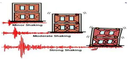
Figure 1.2: Performance objectives under differentintensities of earthquake shaking –seeking low repairable damage under minor shaking and collapse-prevention under strong shaking.
STRUCTURAL RESPONSE TO EARTHQUAKE: The design of structures in earthquake regions has been based upon the assumption of a lateral load proportional to the mass of the building. For example in many areas the structure is designed to carry a “horizontal gravity” force. Such designs are based upon the assumption that the period of natural vibration of the structure is large compared with the typical period of the ground motion.
FACTORS GOVERNING SEISMIC DESIGN: The following factors affect and are affected by the design of the building. It is important that the design team understands these factors and deal with them prudently in the design phase. Torsion: Objects and buildings have a centre of mass, a point by which the object (building) can be balanced without rotation occurring. If the mass is uniformly distributed then the geometric centre of the floor and the centre of mass may coincide. Uneven mass distribution will position the centre of mass outside of the geometric centre causing "torsion" generating stress concentrations. A certain amount of torsion is unavoidable in every building design. Symmetrical arrangement of masses, however, will result in balanced stiffness against either direction and keep torsion within a manageable range.
Damping: Buildings in general are poor resonators to dynamic shock and dissipate vibration by absorbing it. Damping is a rate at which natural vibration is absorbed.
Ductility: Ductility is the characteristic of a material (such as steel) to bend, flex, or move, but fails only after considerable deformation has occurred.
Non-ductile materials (such as poorly reinforced concrete) fail abruptly by crumbling. Good ductility can be achieved with carefully detailed joints.
Strength and Stiffness: Strength is a property of a material to resist and bear applied forces within a safe limit. Stiffness of a material is a degree of resistance to deflection or drift (drift being a horizontal story-to-story relative displacement).
Building Configuration: This term defines a building's size and shape, and structural and
non-structural elements. Building configuration
determines the way seismic forces are distributed within the structure, their relative magnitude, and problematic design concerns. Regular Configuration buildings have Shear Walls or Moment-Resistant Frames or Braced Frames and generally have: Low Height to Base Ratios, Equal Floor Heights, Symmetrical Plans, Uniform Sections and Elevations, Maximum Torsional Resistance. Short Spans and
Redundancy Direct Load Paths. Irregular
Configuration buildings are those that differ from the "Regular" definition and have problematic stress concentrations and torsion.
DIFFERENCE BETWEEN LINEAR AND NON-LINEAR ANALYSIS
LINEAR STATIC ANALYSIS: This approach defines a series of forces acting on a building to represent the effect of earthquake ground motion, typically defined by a seismic design response spectrum. It assumes that the building responds in its fundamental mode. For this to be true, the building must be low-rise and must not twist significantly when the ground moves.
LINEAR DYNAMIC ANALYSIS: Static procedures are appropriate when higher mode effects are not significant. This is generally true for short, regular buildings. Therefore, for tall buildings, buildings with torsion irregularities, or non-orthogonal systems, a dynamic procedure is required.
IJIRT 148820
INTERNATIONAL JOURNAL OF INNOVATIVE RESEARCH IN TECHNOLOGY217
loading that may vary with time. The analysis may belinear or non linear.
NONLINEAR ANALYSIS: The nonlinear static procedures constitute an inelastic analysis that considers what happens to buildings after they begin to crack and yield in response to realistic earthquake motion. This approach differs from traditional static linear procedure that reduces seismic forces to levels that allow to design buildings under the assumption that they remain undamaged. Although unrealistic and potentially misleading, this simplistic approach works well for new buildings and for regular existing buildings.
SECANT METHOD: When the analysis of building is done with the Secant method, a global elastic model of the structure is constructed. Special stiffness values are calculated for the modelled elements and components. The global elastic model is analysed using elastic response spectrum analysis. The ground motion used in the analysis is either a code specified 5 % damped response spectrum or the 5 % site specified spectrum. In general, the response
spectrum analysis will predict a different
displacement pattern than originally assumed.
NON-LINEAR STATIC ANALYSIS:
Pushover analysis is a static, nonlinear procedure in which the magnitude of the structural loading is incrementally increased in accordance with a certain predefined pattern. With the increase in the magnitude of the loading, weak links and failure modes of the structure are found. The loading is monotonic with the effects of the cyclic behaviour and load reversals being estimated by using a modified monotonic force deformation criteria and with damping approximations. Static pushover analysis is an attempt by the structural engineering profession to evaluate the real strength of the structure and it promises to be a useful and effective tool for detailed performance evaluation of building. The pushover analysis can be performed either under load control or displacement control as mentioned below. 1. Load Control: It is used when the load is known (such as gravity load) and the structure is expected to be able to support the full magnitude of the load which is applied in steps. 2. Displacement Control: In this method, the magnitude of the load
combination is increased or decreased as necessary until the control displacement reaches a predefined value. It is used when specified drifts are sought, magnitude of the applied load is not known in advance, structure can be expected to lose strength or become unstable or when displacement occurring in the design earthquake is known.
NONLINEAR TIME HISTORY ANALYSIS
METHOD:
Some buildings may be too complex to rely on the nonlinear static procedure. Those cases may require time history analysis of the nonlinear behaviour of the structure during analysis for a particular example of earthquake. The kinds of the buildings that may require this specialized analysis are highly irregular or complicated. This method is performed using time histories prepared according to the actual ground motions recorded. The requirements for the mathematical model for time history analysis are identical to those developed for response spectrum analysis.
NON-LINEAR DYNAMIC ANALYSIS:
The response of real structures when subjected to a large dynamic input often involves significant nonlinear behaviour which includes the effects of large displacements and/or nonlinear material properties. The use of geometric stiffness and P-Delta analyses includes the effects of first order large displacements. If the axial forces in the members remain relatively constant during the application of lateral dynamic displacements, many structures can be solved directly without iteration.
MODAL ANALYSIS: Modal analysis is used to determine the vibration modes of a structure. These modes are useful to understand the behaviour of the structure. They can also be used as the basis for modal superposition in response spectrum and modal time-history analysis cases.
IJIRT 148820
INTERNATIONAL JOURNAL OF INNOVATIVE RESEARCH IN TECHNOLOGY218
"harmonics". Computer analysis can be used todetermine these modes for a structure. For each mode, a response is read from the design spectrum, based on the modal frequency and the modal mass, and they are then combined to provide an estimate of the total response of the structure.
OBJECTIVES
1. To prepare an architectural drawing of multi-storeyed car parking using Auto- cad
2. To analyse multi-storied parking building.
3. To design multi-storied parking building by
using STAAD-PRO software to promote sustainable building
4. To reduce the parking area by providing multi-storeyed parking building.
5. To provide the safety and secured environment for the parked vehicles.
6. To reduce the traffic congestion.
7. The objective of this project is to effectively manage space by the design of a multi-level car parking decks to curb automobiles.
8. To identify one of the major problem in our city
and to give a technical solution.
SCOPE OF THE PROJECT: The scope of this project behind this work is to prepare a detailed plan of a Multi-Level Car Parking with provision for parking area in each floor (G+4). All the important amenities for a Car Parking have been included. The design of all components such as Beams and Columns has been done with aid of STAAD PRO. The access to each floor has been provided using staircase. The design of staircase and slab has been done in accordance to the Limit state method and confirming to Indian standard code practices.
OUTLINE: The aim of this project is to analyse and design a high-rise building using one of the preferably used software STAAD Pro. The building is designed as a framed structure. We propose use M35 grade concrete for columns and M30 grade concrete for beams and Fe500 bars for all structural components like slabs, beams and columns. Regarding their structural features, they are rectangular buildings. All the columns are arranged in such a way that they form typical frames in length and width direction. The limit state method of
collapse using IS 456:2000 and SP-16 have been adopted for the design of all structural components.
LITERATURE REVIEW
IJIRT 148820
INTERNATIONAL JOURNAL OF INNOVATIVE RESEARCH IN TECHNOLOGY219
vertical parking it‟s called MULTI LEVEL CARPARKING.
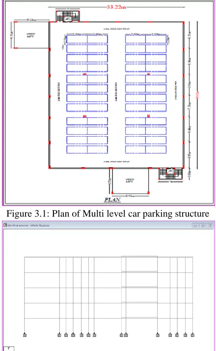
BUILDING DESCRIPTION AND MODELLING: A multilevel car parking structure is a five-storey reinforced concrete building with a floor to floor height of 3 meters. This five-storey multilevel car parking structure is analyzed at seismic zone-III the multilevel car parking structure is designed as a frame model as per Indian standards with joint constraints of ground floor are fixed. A special design of ramp is made for movement of cars from one floor to another. Table 3.1 gives the details of plan area, height of structure and other details of building. Table 3.2 shows the properties of materials and sections used to model the structure. Table 3.3 represents the applied loading details on the building. Figs. 3.1 and 3.2 shows, the plan and elevation of the structure. Fig. 3.3 show, the 3D model created in the Staad.pro software.
Figure 3.1: Plan of Multi level car parking structure
Figure3.2 ELEVATION
Figure 3.3 3D-VIEW
PLANNING OF MULTISTOREY CAR PARKING: MODEL CONSIDERATIONS
Plot Area = 1648.0442 sq.m Car Plot Size = 2.5 m × 5 m
Height of the Floor = 2.8 m (for ground floor) and 3.0m (for remaining floors)
Driveway Width = 4.36 m Total No. of Cars = 240 Cars No. of Cars in each Floor = 48 Cars
Plan Area 33.22m x 49.61m Height of Ground Floor 2.8m
Floor to Floor Height 3m Total Building Height 14.8m
Type of Structure Multilevel car parking structure
Bay of car in X-direction 2.5m Bay of car in Y-direction 5m Support Conditions Fixed Table 3.1 Building Details
Table 3.2 Details of Materials and Section Properties
Table 3.3 Applied Loading Details MINIMUM DIMENSIONS OF PARKING LOTS
Live Load 6 kN/m2 Floor Finishes Load 4.5 kN/m2
Earthquake Load As per IS:1893 (Part-1):2002 Importance Factor, I 1.5
Response Reduction Factor, R
5 (SMRF)
Beam Sizes 500mm x 600mm(for floor beams)
Column Sizes 230mm × 450mm (inner columns) 609.0mm x 609.0mm(centre columns) Thickness of
Slab
120mm
Grade of Concrete
M30 (beams and slab) M35 (columns) Grade of Steel HYSD 500 Density of
Concrete
IJIRT 148820
INTERNATIONAL JOURNAL OF INNOVATIVE RESEARCH IN TECHNOLOGY220
Width 2.4m
Length 4.8m
Table 3.4MINIMUM DIMENSIONS OF CAR PARKING LOTS
Figure 3.4 Minimum
Dimensions of car
parking Lots
Bay dimension: A Parking Stall refers to the space for parking of one motorcar, that is, a car parking lot. The space of the stall should be rectangular. The longer side is known as length and the shorter side is the width. In parallel parking, the longer side is parallel to the parking aisle or driveway. The car bay dimension is taken as 5m x 2.5m.
The minimum dimensions required of a car parking lot are as follows:
The area of each lot shall be flat and free from kerbs and other encumbrances.
Headroom: The recommended minimum clear height or headroom, measured normal to surfaces, for vehicles is 2.10m. Additional clearances are generally needed at changes in gradient such as at ramps. The floor to floor height is taken as 2.80 m for ground floor and 3.0m for remaining floors, which satisfy the minimum height recommended for headroom including deduction made for signage, lighting, ventilation, barrier controls and any other possible projections.
Parking angle: Placing bays at an angle of less than 90° is a convenience for drivers since it facilitates entry and exit. This in turn improves the „dynamic and turnover capacity‟ of the aisle. However, a disadvantage is that greater floor area per car is required. Here parking angle is of 900. Aisle width is taken as 4.6m.
Car park layout: This structure consists of 7 spans of 33.22 meter in X-direction and 5 spans of 49.61 meter in Y-direction. The total height of the building is 14.8m. The plan of structure measures 33.2m x 49.6m.
BUILDING MODELLING, ANALYSIS AND DESIGN ANALYSIS AND DESIGN
GENERAL: This deals with the line of action of project study i.e. the met need to contribute for the achievement of desired goals of it. These methodologies basically have number of steps or set of procedures discussed in this section. The modeling is done using finite element software STADD-Pro.
AUTO-CAD: AutoCAD is a commercial
computer-aided design (CAD) and drafting software
application. Developed and marketed by Autodesk, Auto-CAD was first released in December 1982 as a desktop app running on microcomputers with internal graphics controllers. Prior to the introduction of AutoCAD, most commercial CAD programs ran on mainframe computers or minicomputers, with each CAD operator working at a separate graphics terminal. Since 2010, AutoCAD was released as a mobile- and web app as well, marketed as AutoCAD 360.
MODELLING IN STAAD-Pro V8i SS5: STAAD or (STAAD-Pro) is a structural analysis and design computer program originally developed by Research Engineers International at Yorba Linda, CA in 1997. In late 2005, Research Engineers International was bought by Bentley Systems.STAAD-ProV8i is a comprehensive and integrated finite element analysis and design offering, including a state-of the-art user interface, visualization tools, and international design codes. It is capable of analyzing any structure exposed to static loading, a dynamic response, wind, earthquake, and moving loads. STAAD-Pro V8i provides FEM analysis and design for any type of project including towers, culverts, plants, bridges, stadiums, and marine structures.
MODELLING AND DESIGN PROCEDURE
IJIRT 148820
INTERNATIONAL JOURNAL OF INNOVATIVE RESEARCH IN TECHNOLOGY221
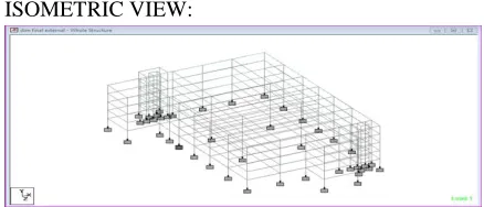
Fig 4.3.1-ISOMETRIC VIEWSUPPORT CONDITIONS: The fixed supports are assigned to the structure.
Fig 4.3.2- SUPPORT CONDITIONS ON THE STRUCTURE
STRUCTURAL PROPERTIES: The beam
dimensions, column dimensions and thickness of slab are assigned to the structure.
Fig 4.3.3- STRUCTURAL PROPERTIES ON THE STRUCTURE, LOADS: The loading that have been considered on the structure are as follows:- 1. Dead load. (Self-weight), 2. Live load, 3. Seismic load 1. Self -weight: It is the weight of the entire structure Generated by STAAD Pro itself with the Self Weight Command.
Fig 4.3.4- SELF WEIGHT ON THE STRUCTURE
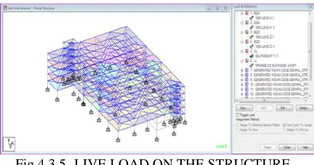
LIVE LOAD: The live load is considered on the structure 6KN/m^2.
Fig 4.3.5- LIVE LOAD ON THE STRUCTURE
SEISMIC LOAD: Under the standard code: IS 1893-2002/2005 considerations the seismic loads are assigned to the structure.
Fig 4.3.6- EARTHQUAKE LOAD ON THE STRUCTURE
LOAD COMBINATION: The combination of dead load, live load and earthquake load is known as load combination. The combinations of loads are assigned to the structure as per IS 456 Code.
Fig 4.3.7- LOAD COMBINATIONS ON THE STRUCTURE
DESIGN OF SLAB: IS 456: 2000 code provisions for design of Slab
1. The clear cover for the tensile reinforcement should not be less than 20mm, or diameter of the bar.
2. Slabs spanning in two directions
IJIRT 148820
INTERNATIONAL JOURNAL OF INNOVATIVE RESEARCH IN TECHNOLOGY222
three-quarters of the width and each edgestrip one-eighth of the width.
Figure4.4.1: DIVISION OF SLABS INTO MIDDLE STRIP AND EDGE STRIP
The maximum moments calculated apply only to the middle strips and no redistribution shall be made. Tension reinforcement provided at mid-span in the middle strip shall extend in the lower part of the slab to within 0.25lof a continuous edge, or 0.15lof a discontinuous edge. Over the continuous edges of a middle strip, the tension reinforcement shall extend in the upper part of the slab a distance of 0.15lfrom the support, and at least 50 percent shall extend a distance of 0.3l. At a discontinuous edge, negative moments may arise. They depend on the degree of fixity at the edge of the slab but, in general, tension reinforcement equal to 50 percent of that provided at mid-span extending 0.1 l into the span will be sufficient. The minimum area of steel should not be less than 0.15% of gross cross sectional area, in case of mild steel bars. Whereas, it is 0.12% of gross cross sectional area in case of HYSD bars. The diameter of reinforcement bars shall not exceed 〖1/8〗^thof total thickness of slab. Maximum size of coarse aggregate shall not exceed 〖1/4〗^thof total thickness of slab. Commonly 20 mm are used. The horizontal distance between two parallel bars shall not less than the greatest of the following: The diameter of bar if the diameters are equal or the diameter of the largest bar if the diameters are unequal. 5mm. more than the nominal maximum size of coarse aggregate.
DESIGN OF STAIRCASE
DIMENSIONS:-
C1 = 0.23*0.30m; 3m = 9‟10‟‟
C2 = 0.23*0.38m; 1ft = 12‟‟= 9*12=108, C3 = 0.30*0.91;108+10=118‟‟ (floor height),
C4 = 0.60*0.60m ; 1 step height (rise)=5‟‟ {Total ht (floor ht)/number of Steps = 118/26 = 4.153‟‟}, Thread = 0.26m = 10‟‟, Landing = 1.52m, The dimensions of risers and threading are 0.115m (115mm) and 250mm (0.25m). Finish loads = 1.5KN/m^2, Live loads = 6KN/m^2, Landing A has the beam while other landing B&C have brick walls. Using concrete grade M20& grade of steel FE500, Design of landing slab A & going (sec11),
Step 1:- Effective span & depth of slab:-
According to IS: 456-2000 clause 33 distribution of landing on stairs:-
Effective one strip =150mm may be deducted from the loaded area & effective breadth of the section is increased by 75mm for the design. Assuming (taken) cover of slab = 25mm, Diameter of main reinforcing bar = 12mm, The inclined length of each step = L^2 =R^2+T^2, =square root of R^2+T^2, =275.180mm
Effective span=150+1450+2060+1300=4960mm,
Depth of the waist slab is assumed as =4960/25=200, Assume depth is 200mm, The effective depth =200-25-6=169mm
Depth of landing slab =200mm overall
depth=200+25=225mm, Effective depth =169mm
Step 2:- calculation of loads:- (1) loads on going (on projected plan area), (a) Self weight of waist slab, =25(0.20)(267/250)=5.34KN/m2, (b) Self weight of
steps =25(0.5)(0.10)=1.25KN/m2, (c) Finishes
(given) =1.5KN/m^2, (d) Live loads (given) =5.0KN/m^2, Total=13.09KN/m^2
Total factored load =1.5*13.09=19.635KN/m^2, (2) Loads on landing slab A:-
(a) Self weight of slab =25(0.20)=5KN/m^2, (b) Finish loads =1.00KN/m^2
(c) Live loads =5KN/m^2, Total load =11KN/m^2, Factored load =11*1.5=16.5KN/m^2
(3) Landing slab B= (50% of loads of landing slab A)=50/100*16.5=8.25KN/m^2
Factored load of landing slab B=8.25KN/m^2, The
total loads:- Total loads going
=19.635(2.06)(1.5)=6.672KN, Total loads landing slab A =16.5(1.45)(1.5)=35.88KN
Total loads landing slab B =
8.25(1.0)(1.5)=12.375KN, Total loads =108.927KN Step3:- bending moment and shear force :-
IJIRT 148820
INTERNATIONAL JOURNAL OF INNOVATIVE RESEARCH IN TECHNOLOGY223
+60.672(5.56-1.30-1.03) +12.375(1.45/2)) /5.56,
=68.54KN
Vd =108.92-68.54=40.37KN, The distance x where the shear force is zero is obtained from:-
68.54-35.88-19.635(1.50) (x-1.45) = 0,
x-1.45=35.88+19.635(1.5)-68.54, x=1.75m The maximum bending moment at x=1.75m,
=68.54(1.75)-(1.5)(16.5)(1.45)(1.75-0.725)-19.635(1.5)*, (1.75-1.45)(1.75-1.45)(0.5) =81.834KN Maximum shear force =68.54KN,
Step 4:- Checking of depth :- ( acc to IS: 456:2000 From the maximum moment table 20
D= ((81834/ (1.5) (2.76)) 1/2 Tcmax=3.5N/mm^2 =140.59mm<169mm for M30)
Hence ok, For the maximum shear force, Tv=68540/(1450)(169) =0.28N/mm^2
The depth of the slab =200mm, K=1.2(from clause 40.2.1.1 of IS456)
Tc=1.2(0.29)=0.348N/mm2, Tv<Tc<Tcmax, the
depth of the slab as 200mm is safe
Step5:-Determination of areas of steel
reinforcement:-
Mu/bd2=81834/ (1.5) (169)(169)=1.91N/mm2, Acc to Sp-16 table-4 P value =0.475
Ast=0.475*1300*169/100, =1043.575mm2/m, No. of
bars required =Ast/ , =1043.575/ ( )
, =9bars, D=dia of the bar, Spacing
=ast/Ast*1000= ( )
Hence, provide 12mm bars at 110mm c/c,
Distribution reinforcement:-
Ast =0.12% of gross area,
=0.12*1000*225/100=270mm2
Using 8mm bars, spacing, S= ( )
Step6:- Checking of development length:-
Ld=Φσs/4Tbd, For M30 concrete grade and Fe500 steel grade. Dia of bar, Φ=12mm, Stress in bar, σs =500N/mm^2
Design bond stress, Tbd =1.5N/mm^2, As per IS 456:2000 M30, Tbd=1.5N/mm^2
Ld=σs/4Tbd*Φ, =500/4*1.875 Φ, =66.66* Φ, =66.66*12, The development of length =66 Φ or 800mm is required
Design of landing slabs B and C &going:-
Step1:-Effective span and depth of slab:- The effective span from the centre line of landing slab B
to the centre line of landing slab C=
1300+2060+1300=4660mm, the depths of waist slabs and landing slabs are maintained as 200mm.
Step2:- Calculation of loads:- (1) Loads ongoing =19.635KN/m2 (same as step2 (i)-A),,(2) Loads on landing slab B=8.25KN/m2 (same as step2 (iii)-A), (3) Loads on landing slab C=8.25KN/m2 (same as step2 (iii)-A)
Total factored loads are:-(1) Total loads ongoing =22.9(2.06) (1.5)=60.670KN, (2) Total loads on landing slab B=8.25(1.0)(1.5)=12.375KN, (3) Total loads on landing slab, C=8.25(1.0)(1.5)=12.375KN, Total =85.422KN,
Step3:- Bending moment and Shear force (width
=1.5m), The total load =85.422KN,
Va=Vb=42.711KN (symmetrically placed), The maximum bending moment at x= 2.780m (centre line of the span 5.56m), =42.711(2.78)-12.375(2.78-0.5)-19.635(1.5)(1.39)(1.39)(0.5),
=62.068KN-M, Maximum shear force =42.711KN, The maximum bending moment and maximum shear force are less than those of the other section, the depth of 200mm. Hence ok
Step4:- Determination of areas of steel
reinforcement:- Mu/bd2=62068/2*169*169
=1.08N/mm2 From table -4 of Sp-16 gives P=0.258, 1.05-0.252, 1.08=? , 1.10-0.265, 1.08-?, 0.252+0.265-0.252/(1.10-1.05)*(1.08-1.05), 1.08=0.2598, Area of steel (Ast) =0.258*1300*169/100 =567mm2, No of
bars required =Ast/ *(12)2 =5 bars, Spacing
=ast/Ast*1000 = ( )
=200mm@c/c
spacing, Distribution bars: - using 8mm bar, 180mm@c/c spacing,
Step5:- Checking of development length:-,
Ld=Φσs/4Tbd, Ld=500/4*1.875Φ =66.66*12
=800mm is required Hence ok.
RESULTS AND DISCUSSIONS
IJIRT 144769
INTERNATIONAL JOURNAL OF INNOVATIVE RESEARCH IN TECHNOLOGY224
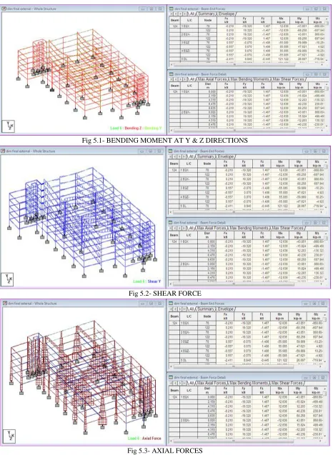
Fig 5.1- BENDING MOMENT AT Y & Z DIRECTIONSFig 5.2- SHEAR FORCE
IJIRT 148820
INTERNATIONAL JOURNAL OF INNOVATIVE RESEARCH IN TECHNOLOGY225
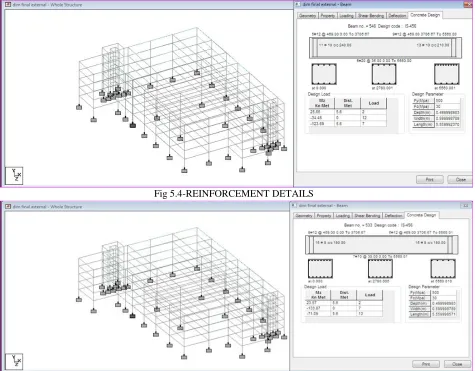
Fig 5.4-REINFORCEMENT DETAILSFig 5.5-REINFORCEMENT DETAILS
RESULTS AND DISCUSSIONS
After analysis the results have been obtained which are mentioned in 5.1, 5.2& 5.3 where bending moment, shear force and axial force are represented. As per fig 5.1 bending obtained at y-z gives the details about the maximum Bending moment is at 529kN-m and Shear force is at 15.80 kN and Axial force is at 7.24kN. Based on these results the
concrete design carried out the complete
reinforcement details structural elements are
represented in 5.4&5.5
CONCLUSION
The traffic congestion problem can be regulated by providing multi storey parking. We hope this project will serve as a solution to various traffic congestion
problems and can be used as a model in the development of storey parking‟s. The multi-level car parking was designed as a complex building with G+4 floors. The analysis and concrete design are done .The layout of the building was planned with reference of Codes to facilitate maximum utility. For emergency purpose separate dog-legged staircase is provide and also the ramp. This project have been focus on improving the parking system to be suitable for the life style.
REFERENCES
[1] Dr. P. S. Pajgade, Radhika A. Dahane P.R.M.I.T
IJIRT 148820
INTERNATIONAL JOURNAL OF INNOVATIVE RESEARCH IN TECHNOLOGY226
[2] S. S. Kudwe, V. U. Mane, G. A. Magdum andS.S.Magdum (2017), “Seismic Response of
Multi-Storied Car Parking Building”.
International Journal of Scientific & Engineering Research, Volume 8(2) pp.1205-1208.
[3] Dr. S. Mahendran, K. Sivasubramanian and M. Ashok Pandiyan (2018), “DESIGN OF MULTILEVEL CAR PARKING BUILDING”. International Journal of Civil Engineering and Technology (IJCIET) Volume 9(11) pp. 1164– 1169.
[4] Pramod.kr, Venkatesh.K and Pawan.R (2018),
“Analysis and design of multi-storeyed parking building proposed at Jalahalli cross, Bangaluru”. International Research Journal of Engineering and Technology (IRJET) Volume: 05 (6) 1091-1024.
[5] Abdul Qayyum, Arun Kumar, Arshan khan and
Raj Kumar (2017), “Review of Multi-Storey Car Parking Building”. International Research Journal of Engineering and Technology (IRJET) Volume: 04 (4) pp.2188-2191.
[6] Eduardo Barata, Luis Cruz and João-Pedro
Ferreira (2012), “Review of Multi-Storey Car Parking Building. International Research Journal of Engineering and Technology (IRJET) Volume: 04(4) pp.2188-2189.
[7] Richard Arnott, John Rowse (2000). “Review of
Multi-Storey Car Parking Building”.
International Research Journal of Engineering and Technology (IRJET) e-ISSN: 2395 -0056 Volume: 04 (4) pp.2189-2190
[8] Saleh Abdul-Aziz and Al-Fouzan (2012),
“Review of Multi-Storey Car Parking Building”. International Research Journal of Engineering and Technology (IRJET) Volume: 04 (4) pp: 2190-2191
[9] Upendra S.D and Rakesh G.A (2016), “study of