4638
IMPLEMENTATION OF LCD INTERFACING
WITH ARM CONTROLLER LPC2148
Dr.Venugeetha Y, Ashwini C, Sudheer Rao Y
Abstract— Display is the necessary part of a machine whether it is any home appliance or industrial machines. Display not only shows the control options to operate the machine but also shows status and output of task performed by that machine. There are many types of displays used in electronics like 7-segment display, Liquid crystal displays (LCDs) display, TFT touch screen display, Light emitting diode (LED) display etc. 16x2 LCD display interfacing with other Microcontrollers(MC) are the most basic one and also used to display in some small electronics equipment. LCDs are extensively used in today’s world to display numbers, characters as well as graphics. Whenever the user wants to get the directions or data values the microprocessors and microcontrollers play a vital role in displaying the letters of the alphabet and numbers. Whenever there is a need for large amount of data to be displayed Cathode ray tube (CRT) is a good option to display the data. On the other hand when a small amount of data is to be displayed, simple digit type displays are generally used. Digit-oriented displays use various technologies. One among these technologies is the use of LCD which is in limelight. In this paper the implementation of LCD interfacing on ARM-7 development board using NXP's LPC2148 to display a suitable text message is presented. The ARM-7 development board is developed with two applications namely keypad interface and the LCD interface using NXP's LPC2148. Keywords— ARM-7, LPC 2148, LCD , LED, 4*4 Matrix Keypad, CRT, MC.
—————————— ——————————
1.
INTRODUCTION
The LPC2148 microcontrollers are based on a 16-bit or 32-bit ARM7TDMI-SCPU with embedded trace support and real-time emulation, which combines microcontroller with embedded high-speed flash memory varying from 32 KB to 512 KB. Memory interface with a width of 128-bitand 32-bit unique accelerator architecture that enables code execution at maximum clock rate. LPC2148 using NXP’s ARM7 Development Kit is projected for ease of progress in develop and debug designs comprising of High speed 32-bit Microcontrollers like LCD interfacing and so on.
LCDs (Liquid Crystal Displays) are used for displaying status or parameters in embedded systems. An LCD display is specifically manufactured to be used with microcontrollers. It cannot be activated by standard IC circuits.Figure1 below shows pin diagram of LCD 16x2. There are pins along one side of LCD. It is a 16-pin device that has data pins 8 in number from D0-D7 along with control pins 3 in number named RS, RW, EN. Other Pins in LCD are supply and backlight pins that are totally 5 in number.
—————————— ——————————
Dr.Venugeetha Y, Professor & Head of Computer Science and Engineering Department, Global Academy of Technology, VTU, Bengaluru, Karnataka, India. E-mail: [email protected]
Mrs.Ashwini C, Assistant Professor, Department of Computer Science and Engineering, Global Academy of Technology, VTU, Bengaluru, Karnataka, India. E-mail: [email protected]
Mr. Sudheer Rao Y, Senior system programmer, Department of Computer Science and Engineering, Global Academy of
Technology, VTU, Bengaluru, Karnataka, India. E-mail: [email protected]
Figure:1 Pin Diagram of LCD 16x2
The LCD display can exhibit 16 character per line and has two lines of characters as shown below in the figure2. Every character is organized in a matrix of pixels. The 16 pins of LCD are divided into data pins and control pins.
Figure:2 LCD Display of 2line*16 character
operate in different modes, we require specific commands which need to be initiate LCD. Once LCD is ready with specific commands to execute then transfer of data in data mode is possible.
2.
LCD INTERFACE
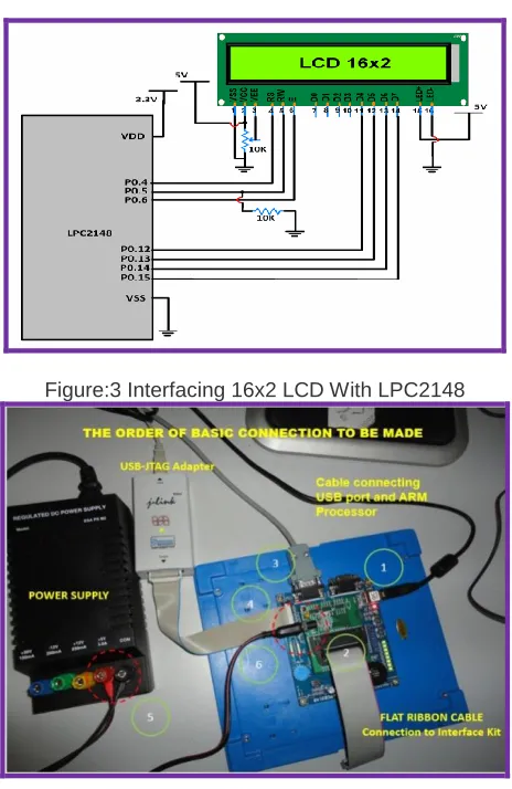
The 16x2 Alphanumeric LCD display with backlight is provided along with the Evaluation board. The LCD is interfaced using the 4-bit mode. The circuit schematic for LCD interface is illustrated in figure3 and interfacing connection using ARM board as shown in figure4.
Figure:3 Interfacing 16x2 LCD With LPC2148
Figure:4 Interfacing Connection Using ARM Board
There are totally two registers in LCD namely Data Register – DR and Command Register also called as Instruction Register – IR
Command register is selectedwhen Register Select RS=0. Once command register is selected, commands are transferred to LCD,and processed there.
When RS=1 data register is selected, and data is sent to LCD, it goes to data register and processed there.
Register Select (RS): The two registers contained in LCD along with RS pin is used for selection. Suppose pin RS=0,various commands like clear display, cursor at home can be performed by sending appropriate commands to instruction command code register.
On the other hand when RS pin is set, data can be sent to
In the implemented system if RS is reset we can send command to the LCD which will be controlled by P0.2port. If pin RS is set then we are sending data to the LCD which will be controlled by P0.2port.
Read/Write: Read /Write pin permits for read from LCD or write onto LCD.
If R/W is reset it is enabled for writing else for Reading. In the implemented system if R/W is reset it is used for writing onto LCD, normally it is grounded. If R/W is set reading operation from the LCD is performed. The RS & R/W specifications are illustrated in table1.
Table 1: RS & R/W specifications
RS RW Status
0 D0 to D7 are command
1 D0 to D7 are data
0 Writing from Microcontroller to LCD
1 Reading from LCD to Microcontroller
Enable EN: Enable pin is used to latch the commands presented to its data pins in LCD.
Based on the data send to the data pins high to low pulse must be applied to EN pin, so that the LCD can latch the data available at the data pins.
In the implemented system EN=0 for Disabling the LCD, If EN is set then LCD is enabled which is controlled by port P0.3.The Enable EN specifications are illustrated in table.2
Table 2: Enable EN specifications EN=0 Lock. Access to LCD is disabled.
EN=1 Unlock. Access to LCD is enabled. Data/Commands are transferred to LCD
Illustration of how ports of ARM board relate to Control and Data pins of LCD board is shown in Figure5.
4640
3.
STEPS TO PROGRAM – DISPLAY OF TEXT ON
LCD
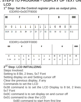
1st Step: Set the Control register pins as output pins.
IODIR0=0x007F8000
IODIR1=0x00FF0000
2nd Step: LCD INITIALIZING
Steps Involved:
Setting to 8 Bit, 2 lines, 5x7 Font Setting display on and Setting cursor off Clear the previous display, if any Commands to set the LCD
0x38 command is to set the LCD Display to 8 bit, 2 lines, 5x7 Font
0x0C command is to set display on and cursor off 0x01 command to clear the LCD
0x80 command to start from first line 0xC0 command to start from second line
3rd Step - Writing Command
Command is passed to D0 to D7 of pins of LCD through PORT1 of Microcontroller then command is passed to IOSET1 Register. But in Port 1 P1.0 to P1.15 not available. Hence we need to shift the command bit pattern to 16th position as shown in the figure6. So command=0x38<<16.
Figure:6 Illustration of shifting bits from 0th position to 16th position of P1
Before passing this value to IOSET1 Register, we need to clear the IOSET1 Register, HenceIOCLR1=0x00FF0000 followed by IOSET1=com_word and then it goes to DDRAM as illustrated in the figure7.
Figure:7 Illustration of IOCLR1 and IOSET1Values
In Port 0, P0.24, P0.26, P0.27 not available and P0.31
output only. Hence IOCLR0=0x003F8000and
IOSET0=0x000x003F8000, RS=RW=E=0 as shown in the figure8.
Figure8: Illustration of IOCLR0 and IOSET0 Values
4.
SUMMARY
OF
0X38
COMMAND
EXECUTION
1st step: Command is placed stored in DDRAM. IOSET1=com_word
2nd step: Command is read from DDRAM and placed on the DR register after reading from DDRAM. IOSET0=0xFB<<15 3rd step: From DR register, Command is stored in IR Register IOSET0=0xF8<<15. E=0, it means access to LCD is locked
4th step: From IR register, Command is written on to Data bit lines D0..D7 of LCD. IOSET0=0xFC<<15. Enable is set to high pulse. LCD is unlocked
Table 3 Summary of command settings RS, RW& E
Step R
S R W
E Status
01 IOSET1= com_word
It goes to DDRAM
02 1 1 0
RS=1, So Data registered (DDRAM) is selected.
RW=1, So read from DDRAM and placed on DR register.
03 0 0 0
RS=0, data placed in on the bit lines D0..D7 are considered as Command. RW=0 , So write the command from DR
Register to Command
Register/Instruction Register (IR) E=0, Access to LCD is locked
04 0 0 1
RS=0, data place in on the bit lines D0..D7 are considered as Command. RW=0, So write the command to LCD,
Data bit lines (D0..D7)
E=1, Access to LCD is unlocked. 1 indicates High pulse.
05 0 0 0
RS=0, data place in on the bit lines D0..D7 are considered as Command. RW=0 , So write the command to LCD E=0, Low pulse set. (From High pulse to
low pulse) .So the command is executed.
5.
FUNCTION TO INITIALIZE THE LCD MODULE
void LCD_init(void){
unsigned long command; command = 0x38 << 16;
Command_Write(command); /* Function set 8-bit, 2line 5*7 font */
command = 0x0c << 16; /* Display on off control. Diplay on, cursor off, */ Command_Write(command); /* blink off */
command = 0x01 << 16; /* Clear the LCD display */ Command_Write(command);
} int main() {
unsigned long com_word;
IODIR0 = 0x007F8000; /* Configure the GPIO0 and GPIO1 as O/P ports */ /*Configure the GPIO0(P0.15 to P0.22)Port0 as output*/ IODIR1 = 0x00FF0000; /*GPIO1 (P1.16 to P1.22)
Port1 as o/p */
LCD_init(); /* Initialize LCD module */ com_word = 0x80 << 16;
Command_Write(com_word);
/*Displaying on first line */
Disp_String(disp1); /* Displays the message on LCD */
com_word = 0xc0 << 16; Command_Write(com_word); Disp_String(disp2); }
/* Display on the second line */
6.
EXPERIMENTAL RESULTS
The output in the form of text message “Global rr Nagar Of Techno Blr” was displayed on the LCD. The first part of the text ―Global rr Nagar” was displayed in the first row and the last part of the text ―Of Techno Blr” was displayed on the second row.
Figure9: Illustration of Experimental setup
Figure10: Illustration of LCD Implementation result
7.
CONCLUSION
4642 choice of the programmer. The main limitation is that the
display being a 16x2 alphanumeric display, the text in the first row cannot exceed 16 characters or numbers and similarly in the last row the text cannot exceed 16 characters or numbers. This limitation can be overcome by using a different LCD which can display more text such as 32x2 alphanumeric display.
REFERENCES
[1] Md. Moyeed Abrar, ―Interfacing An LCD With ARM Controller LPC2148‖: IJEDR,| Vol 6, Issue 1,| ISSN: 2321-9939 ,2018
[2] Datasheet LPC2141/42/44/46/48, Philips semiconductor, October 2005pp.1-2.
[3] Andrew N Sloss, Dominic Symes, Chris Wright, ―ARM System Developer’s guide Designing and optimizing system software‖. USA: Morgan Kaufman publications,2004.