Procedia Computer Science 46 ( 2015 ) 1095 – 1107
1877-0509 © 2015 The Authors. Published by Elsevier B.V. This is an open access article under the CC BY-NC-ND license (http://creativecommons.org/licenses/by-nc-nd/4.0/).
Peer-review under responsibility of organizing committee of the International Conference on Information and Communication Technologies (ICICT 2014) doi: 10.1016/j.procs.2015.01.022
ScienceDirect
International Conference on Information and Communication Technologies (ICICT 2014)
Selective Cache Line Replication Scheme in Shared Last Level
Cache
Nitin Chaturvedi
a,*, Arun Subramaniyan
a, S Gurunarayanan
b aResearch Scholar, Birla Institute of Technology and Science, Pilani, Rajasthan,333031, IndiabProfessor, Birla Institute of Technology and Science, Pilani, Rajasthan, 333031, India
Abstract
In current multi-core systems with the shared last level cache (LLC) physically distributed across all the cores, both initial data placement and subsequent placement of data close to the requesting core can contribute to reducing memory access latency and power consumption. This paper extends a replication scheme that balances between access latency and cache capacity in shared NUCA designs by selectively replicating frequently used cache lines close to the requesting cores. Our scheme reduces completion time by 15% and improves energy consumption by 27% when compared to the Static-NUCA (S-NUCA) management scheme, when simulated on an eight core system.
© 2014 The Authors. Published by Elsevier B.V.
Peer-review under responsibility of organizing committee of the International Conference on Information and Communication Technologies (ICICT 2014).
Keywords:Non-Uniform Cache Architecture (NUCA); Last Level Cache (LLC); Multi-core Processors (CMP)
1. Introduction
As Chip Multiprocessors (CMP) have become the predominant topology for the modern processors, the critical components including the cache of the system are also integrated along with processing cores on a single chip. The cache hierarchy is of primary concern because of its role in controlling the overall throughput of the system.
* Corresponding author. Tel.:+91-1596-245073 Ext.229; fax: +91-1596-244183.
E-mail address:[email protected]
© 2015 The Authors. Published by Elsevier B.V. This is an open access article under the CC BY-NC-ND license (http://creativecommons.org/licenses/by-nc-nd/4.0/).
Peer-review under responsibility of organizing committee of the International Conference on Information and Communication Technologies (ICICT 2014)
With the advent of every new technology there is an exponential increase in chip multiprocessor (CMP) cache sizes and subsequently growing on-chip wire delays, making it harder to implement conventional caches which possess a single, uniform access latency. A large multi-level on-chip cache hierarchy is used to compensate for the increasing discrepancy between off-chip access time and on-chip communication latency. In order to alleviate the effects of increasing wire delays, Non-Uniform Cache Architectures (NUCA) have been proposed in literature. A NUCA partitions the monolithic LLC into multiple smaller banks, with few banks located to the processing cores and a few banks away. This arrangement of banks allows blocks located near the processing cores to be accessed faster than those far away, thus reducing the average access latency to less than the worst case latency. In literature, NUCA organizations have been categorized as static (S-NUCA) and dynamic (D- NUCA). In S-NUCA, a cache block can be located in a single bank of the NUCA cache, whereas D-NUCA is flexible in allowing blocks to migrate between banks as required. D-NUCA provides features like migration of data between multiple banks by using data locality and moves frequently accessed data close to the requesting core. Multiple placement locations for data and migration between multiple banks, makes data access scheme a key constraint in the D-NUCA based architectures. However, since the requesting core and the LLC banks are not located at uniform distances from each other in the on-chip network, access latencies can show great variation and can sometimes contribute to large wire delays. Such Non-Uniform Cache Architectures (NUCA) have been extensively studied in literature1,3. Replication mechanisms
have been proposed to balance between access latency and cache capacity in hybrid LLC designs1,3. In order to
avoid unnecessary penalties of LLC cache misses, the replica creation policy should be considered carefully. An efficient replication scheme must address the following two questions: 1) which of the cache lines must be replicated? 2) at what positions should cache line replicas be inserted? Ideally, frequently used cache lines should be replicated. In contrast to previous works like Victim Replication and Adaptive Selective Replication, our replication decision is based on tracking the re-usability of cache lines. We explain the details of our scheme in Section 4. The rest of the paper is organized as follows: Section 2 describes the related work. Section 3 includes details about the simulation environment. Section 4 provides detailed explanation of the baseline architecture and the proposed selective replication scheme as adapted to this architecture. Section 5 includes the results and Section 6 discusses the conclusions and future work.
2. Related Work
Prior research on memory management in multi-core processors has mostly focused on the last level cache. Shared, private as well as hybrid LLC designs have been extensively reported in previous work1,2,3. All other cache
levels have traditionally been organized as private to a core. Private LLC organizations provide limited cache capacity to a thread and adversely affect applications with large working sets. Shared organizations on the other hand have the flexibility of storing the data of an application in various locations throughout the cache, but at the cost of higher hit latencies since each request has to incur the wire delays imposed by the meshed interconnection network. However their off-chip miss rates are low as compared to private organization because data is not replicated in the LLC. Wire delays in shared LLC design lead to varying access latencies. To address this problem of non-uniform access latencies, Kim et al.1first proposed the non-uniform cache architecture (NUCA) (refer Fig.
1). The whole LLC is heavily banked such that nearer cache banks have much lower access times as compared to farther banks in the shared cache. The efficiency of a migration scheme depends on an accurate data access scheme that was difficult to implement in the past. Kim1was the first to highlight the relevance of the bank access scheme in
D-NUCA organizations. Although block migration enhances D-NUCA benefits, it is limited by the quality of the bank access scheme within NUCA. This work was further extended by Huh et al.3who analyzed different NUCA
organizations and came to the same conclusion that although D-NUCA outperforms other organizations, access policy is of prime importance in shared D-NUCA designs. Since then researchers from both industry and academia have extensively studied policies in NUCA architectures that efficiently manage: block placement3,8,12,14, block
migration11,12,23, replacement13 and lookup5,26. The introduction of CMPs further increased the complexity of the
Fig. 1. Non-uniform cache architecture (NUCA)2
In an alternative NUCA design called NuRAPID proposed by Chisti et al.18, the last level cache is divided into a few large banks in contrast to multiple smaller banks for greater reliability, efficiency and reducing migration frequency. In multi-core systems, cooperative caching was introduced by Chang et al.22to increase the overall cache capacity wherein each core has a private L2 cache. Cache consistency, sharing in their policy are achieved by listening in on all the L2 cache traffic and cooperating in decreasing the conflicts. Another variant of NUCA is proposed by Liu et al. Beckmann and Wood2in their analysis show that migration of blocks is not highly beneficial for CMPs as close to 60% of the total hits in different commercially used workloads were satisfied in the central banks. NUCA replication policies have also gained considerable attention from the research community. Huh et al.3allowed for limited replication of cache blocks after investigating the sharing behavior of different cores in a CMP-NUCA. Adaptive Selective Replication dynamically evaluates the costs and benefits of replication on a per-block basis and adapts to the needs of the workload. Other schemes similar to Adaptive Selective Replication (ASR) are the CMP-NuRAPID18 and Cooperative Caching22 proposals. The above proposals reduce replications but utilize a static mechanism that does not adapt to the needs of different workloads in different phases and other constraints. In order to monitor the utility of different cache blocks, Suh et al.27 used set and way counters. Zhang et al.28used an automatically re-sizable cache with a miss tag buffer that tracks possible cache hits if a full size cache was available. However, Suh et al. made use of the monitored statistics to dynamically partition the ways of a set among working threads and Zhang et al. used it to reduce energy consumption.
3. Experimental Setup
3.1. Baseline Architecture
In our discussion, we assume a last level shared L2 cache as a Non-Uniform Cache Architecture, based on Kim et al.’s D-NUCA design1. We advocate the selective replication of cache blocks in this architecture to provide fast access to the requestors. In order to effectively describe the details of our policy we have outlined a few terminologies like owner bank, bankclusters and banksets used widely by the research community. They are defined below for the sake of completeness.
Owner Bank:The bank in which data is mapped for the first time after an off-chip access using the static address mapping scheme.
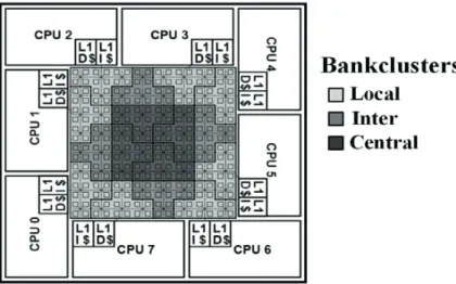
Bankclusters: A group of eight banks compose a bank-cluster and the complete NUCA cache (128 banks) is divided into 16 bank-clusters as shown by the red dotted box in Fig. 2. (a). Every bankcluster has one bank of a logical bankset as described below.
Bankset: All the banks that compose the NUCA cache can be logically imagined to be part of a set-associative structure as shown in Fig. 2 (b) wherein each bank in a bank-cluster holds one way of a logical bankset.
Fig. 2. (a) Multibanked NUCA with bankclusters; (b) Each bank holds one way of the set (16-way bankset associative).
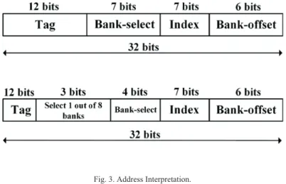
As depicted in Fig. 2. (b), the complete NUCA cache has been partitioned into 128 banks, which is logically organized into a 16-way bankset associative structure (Grey colored banks constitute a bankset). Now, the group of eight banks (bankcluster) that are located closest to the processing cores are called local banks and the eight other banks that are located at the center of the NUCA cache are called central banks (refer Fig. 2. (b)). Therefore, in a bank-set associative NUCA, a cache block can be placed in either the eight local banks or eight central banks (16 possible locations). When a data block is first loaded from main memory, its location is found using the lower bits of the CPU generated address as shown in Fig. 3. The LRU data block in the referenced set of this bank would become a candidate for replacement if the set is completely occupied by data blocks. In Ideal D-NUCA, a cache block can be mapped to any cache bank according to the need. Such a mapping however comes at a significant cost in terms of the search time required and is not preferred. In previous approaches, either tags were stored at a centralized location or were broadcasted to all the banks. To address this issue, our baseline architecture maps cache blocks to a single bank-set. The search mechanism used in our baseline design is based on multicasting data accesses. It proceeds in two steps. In the First step, requests for a data block are sent to the local banks that are close to the core that initiated memory request, and to the eight other central banks. In case all these requests miss, then in the second step, the request is forwarded in parallel to other banks in the bankset. If the request is not satisfied in the remaining 7 banks, then it would be sent to main memory (off-chip). Therefore, when we evaluate NUCA further, we will assume the same NUCA architecture described above in this section with search performed using the two step multicast data access algorithm. The two step multicast data access scheme performs much better than a one-step broadcast scheme that uses significant network bandwidth.
Fig. 3. Address Interpretation.
3.2. Simulation Environment
Presented in this section is the simulation environment that will be used to evaluate the proposed scheme with the system configuration described in Table 1.
Table 1. System Configuration Table 2. Benchmarks
The entire system is simulated using the Virtutech Simics full-system simulator6added with the GEMS framework4. GEMS uses events to provide a complete memory-system timing model that facilitates modeling of a multi-banked NUCA. Furthermore, the RUBY memory system simulator provides support to implement the memory hierarchy of the baseline system. The simulated system is organized on a single chip that consists of eight UltraSPARC IIIi homogeneous cores whose layout is depicted in Fig. 2. Each core has a split L1 cache (data and instruction) that is private to the core. The last level cache hierarchy is the D-NUCA distributed in 128 banks and connected to the cores via switches. We used MOESI based directory protocol to ensure coherent behavior of the memory modules. The main system configuration parameters used in our simulations are shown in Table 1. To quantitatively analyze the proposed scheme, we used two different cases: 1) Multi-programmed and 2) Parallel workloads. The first one uses a reference input set size to execute workloads of the SPEC CPU06 suite, fast forwarded to the beginning of the
region of interest(ROI). Table 2 shows the different workloads that have been used in our simulation experiments.
Parameter Value
No. of cores 8
Core mode Single thread
Frequency 1 GHz
L1-Data Cache 32 kB, 64 bytes L1-Instruction Cache 32 kB, 64 bytes Shared L2 cache 8 MB, 128 banks Bank size 64 kB, 8-way, 64 bytes
Benchmarks Applications Input PARSEC Blackscholes, Bodytrack,
Canneal, Facesim, Fluidanimate, x264, Raytrace, Swaptions, Streamcluster
sim-large
SPEC2006 Mix of different applications: gcc, ibm, astar, mcf, soplex, perlbench
The Parallel workload simulates applications from the PARSEC v2.0 benchmark suite7with sim-large inputs. In our
simulation method, we skip the thread initialization phases and the part that corresponds to the booting of the operating system. In order to eliminate the cold start misses, we fast-forward program execution to the ROI while warming up the cache for 500 million cycles. Then the simulation was switched from atomic to the detailed mode for the next 500 million cycles. To measure performance we used the number of instructions committed per cycle25.
While evaluating the dynamic energy consumed by our memory sub-system, we considered the following three contributions: Energy dissipated in the interconnection network, energy consumed during bank access as well as the extra energy required for every access to the main memory, located off-chip.
Edynamic= Enetwork + Ebanks+ Eoffíchip (1)
For our second performance metric, we used the per access energy consumed. It is based on the energy per instruction (EPI)20commonly used for the analysis of the energy consumed by different cores located on the same
die. This metric is ideal for analyzing throughput and is independent of the time required to process different instructions.
4. Replication Policy: Owner bank knows when to replicate
In this section, we propose an efficient, highly accurate and low-overhead mechanism to track the re-usability of each cache line in the shared NUCA. Our scheme allows dynamic replication of those cache lines that shows high usage at the shared LLC. When a replicated cache line is evicted or invalidated, the proposed scheme dynamically adjusts its future replication decision. This scheme also reduces access latency and power dissipation by selectively replicating the cache line that shows high re-usability to the local bank-cluster of the core that initiates the request. It also maintains coherence complexity similar to that of a conventional non-hierarchical coherence protocol as replications are allowed only in the local bank cluster of the requesting core. The extra coherence complexity arises only when the replicated cache line is replaced or invalidated from the bank-cluster located close to the core.
4.1. Working of the Proposed Scheme
For proper working of the proposed scheme, we identified four key requirements for efficient cache line replication in the NUCA cache. The first involves selecting a cache line for replication. The second one is the intelligent placement of the replicated cache line. The third requirement is the lookup mechanism capable of quickly locating the replicated cache line within the shared cache and finally maintaining cache coherence for the replicated cache lines. We first define few terms to facilitate describing our proposed scheme.
Owner Bank: The bank where data is placed first after being brought from off-chip memory. All the subsequent off-chip requests are serialized at this bank for maintaining coherence and resolving false misses.
Copy Sharer: A core that is given access to a separate cache line copy in its Local bank cluster.
Non-copy sharer: A core that is acting as a simple sharer of the cache line and has not received a separate copy of the line in its Local bank cluster.
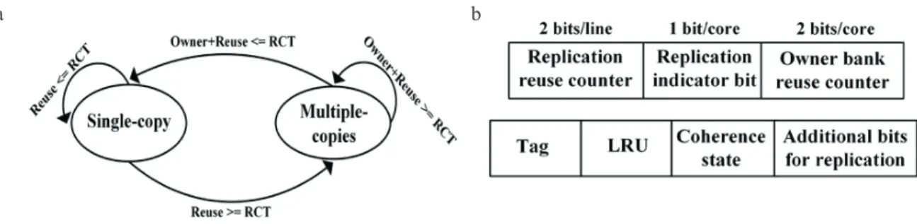
Fig. 4. (a) State transition based on the value of reuse threshold; (b) Additional in-line directory bits for the proposed scheme. Owner bank reuse: The number of times a cache line is accessed at the owner bank before being evicted or written. Replicated line reuse: The number of times the local copy of the replicated cache line is accessed before it is invalidated or evicted.
Reuse threshold (RCT): If the value of re-usage becomes equal to or greater than this value, then a separate copy of the cache line is created.
Note that for any cache line, one core can be a single copy sharer while other cores can be non-copy sharers of the cache line. So, initially all the cores are non-copy sharers of the cache line as shown in Fig. 4 (a) .We have used a directory based coherence protocol, in which each cache entry is further extended with an extra replication indicator bit (RIB) and a 2 bit saturating counter (RCT-1) as shown in the Fig. 4. (b). Based on the value of RCT-1 and the status of RIB, the cache controller allows creating a separate copy of the cache line in the local bank-cluster.
4.2. Managing Read/Write Request
This section describes how our proposed scheme manages a read/write request and handles evictions and invalidations for replicated cache lines.
4.2.1. Read Request
As a result of a compulsory cache miss, a block of data is loaded into the cache from main memory located off-chip. The cache controllers are designed in such a way that on a L1 cache read miss, it first searches the local bank cluster of the requesting core. If the request hits, the block is inserted in the private cache of the requesting core. In addition, if this is the replicated copy of the cache line then the corresponding replication reuse counter (RCT-2) should be incremented to keep track of the line reuse information. In our scheme, for a newly replicated cache line, the counter RCT-1 is reset to 1 and RCT-2 is incremented on every request that results in a hit. Fig. 4. (b) shows the directory entry to track a replicated cache line. On a local bank-cluster miss, the memory request is sent to the owner bank by using the lower address bits of the block address (Fig. 3), beginning the next stage of the search mechanism. If the data block is found, the request hits and the block is sent to the request initiator, thereby completing the search mechanism. In case the cache line is absent in the owner bank, the memory request is forwarded to the next level. Algorithm-1, presents how to handle read requests from the cores. To ensure the correct operation and accuracy of our proposed block replication policy, the in-line cache directory entries are extended with extra bits as shown in Fig. 4. (b), to keep a track of reuse as well as replicated line information. These additional bits include the Replication indicator bit (RIB), which identifies whether a replicated copy of a cache line is created. If it is set to 1, then an extra copy of cache line is placed in local bank-cluster of the requesting core. Secondly, there is a separate owner bank reuse counter (RCT-1) for each core. This counter is used to track the number of times the line is accessed by a core at the owner bank. Initially, it is reset to zero and is incremented on every access to the owner bank. If this counter reaches the reuse threshold (RCT) then RIB is set to 1 and a separate copy of the cache line is
placed in the local bank cluster of the requesting core. If the value of RCT-1 is less than the reuse threshold (RCT), then the cache line is inserted in the private L1 cache of the requesting core, without being replicated. In order to better understand algorithm-1 and algorithm-2, let the set C = {C0, C1, C2, C3, C4, C5, C6, C7} represent the cores as
described in the baseline NUCA architecture. Let L1 = {L10, L11, L12, L14, L15, L16, L17} be their respective
private L1 caches. We use BClocaland BCownerto refer to the local and owner bankclusters respectively.
Also assumed is a LRU based replacement policy, implemented using a queue. In our analysis, we have considered few special cases that could further accelerate our proposed policy. For example, during the initial search into the local-bank cluster closer to the core, it is possible for the same bank to be the owner bank and the read request can be handled directly at the local bank cluster of the core, resulting in reduced number of steps. In this case, even if the replication indicator bit (RIB) is set to 1 (to create a copy of replicated line) the cache line is only inserted at the requestor’s private L1 cache, without being replicated.
Algorithm 1 ##Read request 1: function handleReadRequest
2: INPUT: ReadReq jfrom CiʇʇC
3:Begin:
4: Lookup L1i
5:if(hit) 6: Load Line j
7: LRUQueueset .movetoEnd(Linej)
8: else
9: Fwd ReadReq jĺ%&local
10:if(hit) 11: Load Linej
12: LRUQueueset.movetoEnd(Linej)
13: RCT-2 ++
14:else// local bank-cluster miss
15: Fwd ReadReq jĺBCowner 16:if(hit) 17:if(RCT-1 > RCT) 18: RIBĸ1 19:endif // Line 17 20:if(RIB == 1)
21: BClocal.insertReplica (Line j)
22: RCT-1ĸ/RDGLine j
23: else// RIB != 1
24: RCT-1 ++, Load Linej
25: LRUQueueset.movetoEnd(Line j)
26:endif // Line 20
27:else //owner bank miss
28: Fwd ReadReq jĺoff-chip
29:endif // Line 16
30:endif // Line 10
31:endif // Line 5
32:End // Line 3
Algorithm 2## Write request 1: function handleWriteRequest
2: INPUT: WriteReq jfrom CiʇʇC
3: Begin: 4: Lookup L1i
5: if(hit)
6: Write Linej,update LRU state
7:else //miss
8: Fwd WriteReq jĺBClocal
9: if(hit && cacheLinej.state == M/EX)
10: L1i.insert (Linej)
11: RCT-2 ++
12: Write Linej,update LRU state
13: elsif(hit && cacheLinej.state == S)
14: Fwd WriteReq jĺBCowner
15: Send Inv.ĺL1 copies, copy-sharers 16: RCT-1other sharersĸ0
17: Recv. Inv. Ack
18: if(Ci.isCopySharer(Linej))
19: Send RCT-2ĺBCowner
20. Decide Replica status Ci
21: endif // Line 18
22: cacheLinej.stateĸEX
23: L1i.insert (Linej), Write Linej
24: update LRU state
25: if (Ci.isSingleSharer (Linej)) 26: RCT-1 ++ 27: else 28: RCT-1ĸ1 29: endif // Line 25 30: endif // Line 9 31: endif // Line 5 32: End // Line 3
4.2.2. Write Request
In this section, the details of write requests handled by our proposed scheme are presented. In case of a write request, the cache controller first checks the private L1 cache. If it is not present in exclusive state it results in a miss and the local bank cluster is probed for the replicated cache block. In case the replicated cache line exists in the exclusive or modified state, it is moved to the private L1 cache and its reuse counter is incremented. If the replicated cache line is present in the shared state or if it does not exist, then the request is forwarded to the owner bank depending on the least significant bits of the requesting address as shown in Fig. 3. Upon receiving the request, the owner bank checks the directory information for that line and sends INV (invalidation) requests to all other sharers and L1 copies to maintain the single-writer and multiple reader case, thereby simplifying the coherence protocol complexity. Once the invalidation acknowledgements are received, the owner reuse counter (RCT-1) of all the non-copy sharers are reset to 0 except for the requesting core since they have not shown enough cache line reuse. If the requesting core is the only sharer then its owner reuse counter (RCT-1) is incremented otherwise it is reset to 1. Algorithm 2, illustrates how to handle write requests for the cache line.
4.2.3. Invalidation Request
In case of an invalidation request, if a copy of cache block is present in any of the caches (L1 or local bank-cluster), an acknowledgement is sent to the owner bank. In case a replicated cache block exists, then the replica reuse counter is communicated back with acknowledgement. This information is used to decide whether the core will maintain replica status or not. If the value of RCT-1+RRC-2 (owner reuse + replicated line reuse) is greater than the threshold then the line maintains replica status, otherwise it is demoted to the status of a non-copy sharer.
4.2.4. Eviction Request
On an L1 cache line eviction request, the local bank-cluster is probed for the same address. If a replicated block exists, then the dirty data in the L1 cache is merged with it, otherwise an acknowledgment is sent to the LLC owner bank. In case the replicated cache line in the local bank cluster is evicted then the L1 cache is searched for the same address and invalidated. An acknowledgment is sent to owner bank with the replicated line reuse counter information. If RCT-2(reuse counter) >=RCT, then the core maintains copy status, otherwise it is demoted to non-copy status.
4.3. Hardware Overhead of Proposed Policy
The proposed replication policy requires additional hardware to implement selective replication of blocks within the shared LLC. As shown in Fig. 4. (b), each directory entry requires 2 bits for RCT-2 (for an optimal threshold of 4), 1 extra bit to store RIB and 2 bits for RCT-1. Hence, the proposed scheme requires an additional (8X3) +2 = 26 bits of storage per LLC directory entry. Therefore, the extra number of bits required per bank is 128X8X26 = 3.25kB. So, as per our baseline configuration with 8 MB LLC, the excessive hardware requirement of the proposed scheme is 416kB (5.1%). The proposed selective replication scheme can be easily extended to tiled CMPs as well and is not restricted to NUCA based designs. In addition to the hardware overhead, there is additional complexity in cache design partly because of the additional latency introduced by comparison with the threshold, which is taken care of in our design.
4.4. Cache Coherence Protocol
Our work uses a modified directory protocol to maintain cache coherence in the system. We also believe that future CMPs containing a large number of cores will rely on a similar structure to maintain coherence. To ensure correctness and to implement different read and write scenarios, certain extra states (transient states) are incorporated. Transient states usually include states where the controller is waiting for acknowledgements or data to be received. Our protocol implementation inherits such transition states from the baseline cache coherence protocol and uses these transient states to maintain a coherent view of the system. For cache lines that exhibit simple sharing behaviour, the implemented protocol works similar to the baseline cache coherence protocol. For all cache lines in the shared NUCA, we enforce a write-invalidate policy. The coherence protocol is an extension of a write-invalidate
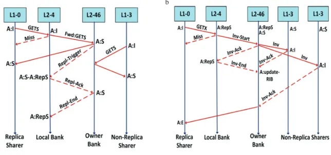
directory protocol, which is a modified baseline MOESI protocol. Race conditions are handled using busy or active states for each request. Fig. 5. (a) briefly describes the working of the proposed protocol for a simple cache line replication example, and the sequence diagram in Fig. 5. (b) describes block invalidation. The arrows represent a specific location in the system with a hypothetical time line. From left to right, these locations are the requester core, the L2 shared cache which also includes the directory that is co-located, the consumer cores, and the main memory. a b
Fig. 5. (a) Sequence diagram for block replication; (b) Sequence diagram for block invalidation.
For clarity in explanation, the above sequence diagrams assume a single requesting core for the cache line along with other non-replica sharers. Also, we assume that initially the cache line is in the OWNED state in the requestor’s cache. The directory is co-located with each cache line and it tracks the coherence state of cache lines belonging to different cores.
4.5. Verification of Protocol
Modified MOESI based directory protocol relies on the fundamental cache coherence protocol to maintain coherence and correctness. Therefore, before the modified protocol is put into operation, it is essential to verify its robustness when subjected to different race scenarios. A robust coherence protocol is required to ensure correctness under all possible conditions. For the verification of the modified coherence protocol, we have used the stress testers provided by the GEMS toolset. By stress testing over a large design space encompassing all possible race conditions, certain coherency issues were identified and the protocol was suitably modified and corrected.
5. Results
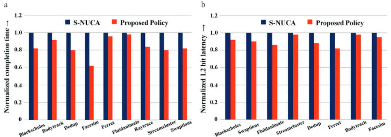
This section compares the results of the execution of selected applications from the PARSEC multithreaded benchmark suite7to completion using sim-large input set. We have used energy consumption of the shared cache and the completion time as the reference performance metrics. We have also analyzed the network traffic in terms of the bytes-per-instruction and L2 miss latency to further evaluate our proposal. For applications with high miss rate, our scheme outperforms the S-NUCA baseline architecture by 8% as shown in Fig. 6. By taking advantage of selective replication for highly reused cache lines at the owner bank, memory requests are directly satisfied by only
accessing the local bankcluster. Fig. 6. (a) compares the completion time (normalized) for selected applications and it was observed that in none of the considered benchmark applications, performance is degraded.
a b
Fig. 6. (a) Normalized Completion Time; (b) Normalized L2 Hit Latency.
In most of the applications, completion time reduction varies from about 4% up to 36%. On average, this translates to about 8% increase in performance. Fig. 6. (b) compares the average L2 hit latency between S-NUCA and the proposed selective replication scheme. With the proposed replication scheme, L2 response time reduces 12% on average by 12%; this is due to the fact that most of the cache hits occur in the local-banks and the requested blocks can be sent to the core in very less time. For few applications like Streamcluster and Bodytrack, we have observed low L1 miss rate, so they can’t take gain much from the proposed policy but there is no further degradation in their performance. Therefore, for the applications with higher miss rates, the impact on the performance is even better. In the second scenario, we have observed applications with low miss rate, like Dedup and Swaptions. In this scenario both the schemes take equal access latencies when the request hits in the closest banks. With applications having very high hit rate like Bodytrack, we have observed slight performance improvement. We assume that the applications running on future processors will follow the behavior presented in the first case, consisting of benchmarks with large working sets and many of them running simultaneously.
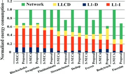
In general, our scheme shows good performance improvement with almost all benchmarks of the PARSEC suite, with more than 8-10% improvement for the Ferret application. Fig. 7 presents the distribution of the data as well as control messages that affect the overall network traffic. In our architecture the size of control message is 8 bytes (header only) whereas the size of the data message is 72 bytes which contains 8 bytes for the header portion and 64 bytes for the data block. From Fig. 7, it can be observed that the total network traffic is reduced in all the programs which are the result of selective replication of cache lines at the closer banks (local bank-clusters). The closer banks are the banks in the local bank-cluster that are located near the cores. This reduces the network distance travelled by a packet to reach the destination bank. In the proposed policy the data packets reach the destination with fewer number of hops as compared to S-NUCA, as seen in the graph and the data portion of the network traffic is reduced whereas the control part of the network traffic remains almost the same. In our proposed policy, the selective replication and then invalidation for read-write blocks is invoked only for a small number of times as compared to the total number of L2 accesses. As a consequence, the total overhead of replication and invalidation messages has a low effect on the total network traffic. Reduction in network traffic reduces dynamic energy consumption as shown in Fig. 8 because of the reduced overall network activity. Fig. 8 shows the dynamic energy consumption of each benchmark using the proposed selective replication policy. The energy reduction can be primarily attributed to the reduction in network traffic. Therefore, for benchmarks where our proposal improves the L2 performance, the energy benefits will in fact be higher. We observed that the proposed scheme improves energy consumption of the NUCA cache by more than 27% as compared to the S-NUCA baseline architecture.
Fig. 8. Normalized Energy Consumption.
To summarize, the proposed selective replication policy reduces energy consumption and enhances performance as compared to other last level shared NUCA data management schemes. We explored all values of RCT between 1 and 8 and found that they provide no additional insight beyond a threshold value of 4. The proposed policy makes use of data locality on-chip and reduces off-chip miss rate. Overall, our replication policy consumes 27% lower energy and shows 15% lower completion time when compared to S-NUCA.
6. Conclusions
We have proposed an efficient selective replication policy for the last level cache. The cache line re-usability is profiled dynamically using in-directory reuse counters. On a set of multi-threaded applications, our selective replication policy reduces the overall energy by 27% and the completion time by 15% when compared to the
Static-NUCA L2 cache management policy. The coherence complexity of our protocol is almost identical to that of a traditional non-hierarchical (flat) coherence protocol since replicas are only allowed to be created at the LLC slice of the requesting core. Our proposed policy is implemented with an extra storage overhead of 5.1% per NUCA bank. References
1. Kim C, Burger D, Keckler SW. An adaptive, non-uniform cache structure for wire-delay dominated on-chip caches. In:Procs. of the 10th
International. Conference on Architectural Support for Programming Languages and Operating Systems; 2002.
2. Beckmann BM and Wood DA. Managing wire delay in large chip-multiprocessor caches. In:Procs. of the 37thInternational Symposium on
Microarchitecture; 2004.
3. Huh J, Kim C, Shafi H, Zhang L, Burger D, Keckler SW. A NUCA substrate for flexible CMP cache sharing. In:Procs. of the 19th ACM
International Conference on Supercomputing; 2005.
4. Martin MMK, Sorin DJ, Beckmann BM, Marty MR, Xu M, Alameldeen AR, Moore KE, Hill MD, and Wood DA. Multifacet’s general execution-driven multiprocessor simulator (GEMS) toolset. In:Computer Architecture News; 2005
5. Ricci R, Barrus S, Balasubramonian R. Leveraging bloom filters for smart search within NUCA caches. In:Procs. of the 7th Workshop on
Complexity-Effective Design; 2006.
6. Magnusson PS, Christensson M, Eskilson J, Forsgren D, Hallberg G, Hogberg J, Larsson F, Moestedt A, Werner B. Simics: A Full system Simulator Platform. Computer; 2002;35-2, p. 50–58.
7. Bienia C, Kumar S, Singh JP, Li K. The PARSEC benchmark suite: Characterization and architectural implications. In:Procs. of the
International Conference on Parallel Architectures and Compilation Techniques; 2008.
8. Bardine A, Foglia P, Gabrielli G, Prete CA. Analysis of static and dynamic energy consumption in NUCA caches: Initial results. In:Procs. of
the Workshop on Memory Performance: Dealing with Applications, Systems and Architecture; 2007.
9. Wang HS, Zhu X, Peh LS, Malik S. Orion: A power- performance simulator for interconnection networks. In:Procs. of the 35th International
Symposium on Microarchitecture; 2002.
10. Micron. System power calculator. In: http://www.micron.com/; 2009.
11. Hammoud M, Cho S, Melhem R. Dynamic cache clustering for chip multiprocessors. In: Procs. of the International Conference on
Supercomputing; 2009.
12. Kandemir M, Li F, Irwin MJ, and Son SW. A novel migration-based NUCA design for chip multiprocessors. In:Procs. of the International
Conference on Supercomputing; 2008.
13. Lira J, Molina C, Gonzalez A. Last bank: dealing with address reuse in non-uniform cache architecture for CMPs. In: Procs. of the
International Conference on Parallel and Distributed Computing; 2009.
14. Muralimanohar N, Balasubramonian R. Interconnect design considerations for large NUCA caches. In:Procs. of the 34th International
Symposium on Computer Architecture; 2007.
15. Chaudhuri M. PageNUCA: Selected policies for page-grain locality management in large shared chip-multiprocessor caches. In:Procs. of the
15th IEEE Symposium on High-Performance Computer Architecture; 2009.
16. Merino J, Puente V, Gregorio JA. SP-NUCA: A cost effective dynamic non-uniform cache architecture. In: ACM SIGARCH Computer Architecture News; 2008. p. 64–71.
17. Hammoud M, Cho S, Melhem R. ACM: An efficient approach for managing shared caches in chip multiprocessors. In:Procs. of the 4th
International. Conference on High Performance and Embedded Architectures; 2009.
18. Chishti Z, Powell MD, Vijaykumar TN. Distance associativity for high-performance energy-efficient non-uniform cache architectures. In Procs. of the 36thInternational Symposium on Microarchitecture; 2003.
19. Hsu L, Iyer R, Makineni S, Reinhardt S, Newell D. Exploring the cache design space for large scale CMPs. In: SIGARCH Computer Architecture News; 2005.33(4).p.24–33.
20. Srikantaiah S, Kandemir M, Irwin MJ. Adaptive Set Pinning: Managing Shared Caches in Chip Multiprocessors. In: Procs. of International.
Conference on Architectural Support for Programming Languages and Operating Systems,ACM/IEEE; 2008. p. 135-144.
21. Guz Z, Keidar I, Kolodny A, Weiser U. Nahalal: Cache organization for chip multiprocessors. In:IEEE Computer Archiecture. Letters; 2007.6-1.
22. Chang J, Sohi GS. Cooperative caching for chip multiprocessors. In:Procs of the 33rd Annual International Symposium on Computer Architecture; 2006. p. 264–276.
23. Liu C, Sivasubramaniam A, Kandemir M, Irwin MJ. Enhancing L2 organization for CMPs with a center cell. In: Procs of the 20th
International Parallel and Distributed Processing Symposium; 2006. p.10.
24. Muralimanohar N, Balasubramonian R, Jouppi NP. Optimizing NUCA organizations and wiring delays alternatives for large caches with CACTI 6.0. In:Procs. of the 40th International Symposium on Microarchitecture; 2007.
25. Wenisch TF, Wunderlich RE, Ferdman M, Ailamaki A, Falsafi B, Hoe JC. Simflex: Statistical sampling of computer system simulation. In:
IEEE Micro; 2006.26-4.p.18–31.
26. Akioka S, Li F, Malkowski K, Raghavan P, Kandemir M, Irwin MJ. Ring data location prediction scheme for non-uniform cache architectures. In:Procs. of the International Conference on Computer Design; 2008.
27. Suh GE, Rudolph L, Devadas S. Dynamic Cache Partitioning for CMP/SMT Systems. In:Journal of Supercomputing;2004. p. 7–26. 28. Zhang M and Asanovic K. Victim Replication: Maximizing Capacity while Hiding Wire Delay in Tiled Chip Multiprocessors. In:Procs. of