Edwin Mangwende
Thesis presented in partial fulfilment of the requirements for the degree Master
in Engineering at Stellenbosch University in the Department of Electrical and
Electronic Engineering
Study leader:
Prof. H.J Vermeulen
i
I would like to acknowledge and appreciate Prof HJ Vermeulen for his valuable assistance, guidance and efforts throughout the course of this project, without which this study would not have been possible. In the same breath, I would like to thank Mr Nelius Bekker for all his assistance and extend my gratitude also to my mother, father, brothers and Clyde for their enormous amount of support they provided during my study.
ii
Declaration
By submitting this thesis electronically, I declare that the entirety of the work contained therein is my own, original work, that I am the sole author thereof (save to the extent explicitly otherwise stated), that reproduction and publication thereof by Stellenbosch University will not infringe any third party rights and that I have not previously in its entirety or in part submitted it for obtaining any qualification.
Signature: ……… December 2019
E. Mangwende
Copyright © 2019 Stellenbosch University All rights reserved
iii
The integration of renewable energy resources is becoming more appealing, specifically Wind Turbine Systems (WTS) due to the innovative ways in which they are designed. These innovative designs make them economic viable to be used in power generation applications. Small wind turbine systems are ideal to reduce the power losses associated with feeding remote distribution grids, as these systems can be installed close to the loads. These systems are known as distributed generation as they are connected to the distribution network level, rather than to the transmission level as is the case for traditional generation systems.
In this study the dynamic behaviour of a 15 kW, fixed speed fixed pitch downwind turbine that can form part of a distributed generation system, is investigated. The small wind turbine system uses a Slip Synchronous Permanent Magnet Generator (SS-PMG) also known as Slip Synchronous Generator (SSG). The generator is a direct driven and direct grid connected generator. This configuration is more efficient and reliable than traditional configurations, since the losses and cost associated with the gearbox and converter electronics, as well as the maintenance cost of these components, are eliminated.
To study the dynamic behaviour of the WTS, both the mechanical and electrical components that form the system are modelled in the Simulink and DigSILENT platforms. The mechanical model comprises of the wind model, aerodynamic model and the mechanical drive train of the system whilst the electrical model consists of the SSG model and grid model. The new concept generator is an SSG whose build-in DigSILENT model does not exist. To study the dynamic behaviour of the WTS in DigSILENT a model is developed by transformation the SSG to a Permanent Magnet Synchronous Generator (PMSG). The PMSG is then implemented using the existing synchronous generator model of DigSILENT with a fixed field excitation. The rest of the mechanical system is modelled using the DigSILENT Simulation Language (DSL).
Using the models developed from the dynamic equations, the transient stability of the system is analysed. A benchmark network for the weak power network with embedded WTS is represented as a Thevenin equivalent circuit. The network is analysed for single and three-phase faults. The systems interaction with the grid network is also analysed and whether the SS-PMSG is capable of Low Voltage Ride Through (LVRT) is investigated. Finally, the simulated results of both the Simulink and DigSILENT model are presented and compared.
iv
Die integrasie van hernubare energiehulpbronne word meer aanloklik, veral Wind Turbine Stelsels (WTS) as gevolg van die innoverende maniere waarop hulle ontwerp word. Hierdie innoverende ontwerpe maak hulle ekonomies lewensvatbaar om in kragopwekking toepassings gebruik te word. Klein wind turbine stelsels is ideaal om die drywingsverliese wat verband hou met die verspreiding van afgeleë verspreidingsnetwerke te verminder, aangesien hierdie stelsels naby die laste geïnstalleer kan word. Hierdie stelsels staan bekend as verspreide generasie aangesien hulle gekoppel word op verspreidingsnetwerkvlak, eerder as die transmissievlak soos in die geval van tradisionele generasiestelsels
In hierdie studie word die dinamiese gedrag van 'n 15 kW, vaste-spoed vaste-invalshoek wind turbine, wat deel kan uitmaak van 'n verspreide generasie stelsel, ondersoek. Die klein wind turbine stelsel gebruik 'n Slip Sinchrone Permanent Magneet Generator (SS-PMG), ook bekend as Slip Sinchrone Generator (SSG). Die generator is 'n direkte-aangedrewe en direkte netwerk gekoppelde generator. Hierdie konfigurasie is meer doeltreffend en betroubaar as tradisionele konfigurasies, aangesien die verliese en koste verbonde aan die ratkas en omskakel elektronika, sowel as die onderhoudskoste van hierdie komponente, uitgeskakel word.
Om die dinamiese gedrag van die WTS te bestudeer, word beide die meganiese en elektriese komponente waaruit die stelsel bestaan gemodelleer in die Simulink en DigSILENT platforms. Die meganiese model bestaan uit die wind model, aërodinamiese model en die meganiese aandryfstelsel van die stelsel terwyl die elektriese model uit die SSG model en netwerk model bestaan. Die nuwe konsep generator is 'n SSG waarvoor 'n ingeboude DigSILENT-model nie bestaan nie. Om die dinamiese gedrag van die WTS in DigSILENT te bestudeer, word 'n model ontwikkel deur die SSG te transformeer na 'n Permanente Magnetiese Sinkroniese Generator (PMSG). Die PMSG word dan geïmplementeer met behulp van die bestaande sinkroniese generator model van DigSILENT met 'n vaste veldopwinding. Die res van die meganiese stelsel word gemodelleer met behulp van die “DigSILENT Simulation Language (DSL)”.
Deur gebruik te maak van die modelle wat ontwikkel is uit die dinamiese vergelykings, word die oorgangstabiliteit van die stelsel geanaliseer. 'n Maatstaf netwerk vir die swak kragnetwerk met geïntegreerde WTS word voorgestel as 'n Thevenin ekwivalente stroombaan. Die netwerk word geanaliseer vir enkel- en driefase foute. Die stelsel interaksie met die netwerk word ook geanaliseer en daar word ondersoek of die SS-PMSG Lae Spanning Deur Ry (LSDR) vermoë het. Ten slotte word die gesimuleerde resultate van beide die Simulink en DigSILENT-model aangebied en vergelyk.
v
Acknowledgements ... i
Declaration ... ii
Abstract ... iii
Opsomming ... iv
Chapter 1: Project Motivation and Project Description ... 1
1.1 Introduction ... 1 1.2 Project motivation ... 3 1.3 Project description ... 5 1.3.1 Overview ... 5 1.3.2 Project objectives ... 6 1.3.3 Research questions ... 6 1.3.4 Research tasks ... 6 1.4 Overview of report ... 7
Chapter 2: Literature review ... 8
2.1 Overview ... 8
2.2 Wind maps ... 10
2.3 Wind turbine classification ... 10
2.3.1 Overview ... 10
2.3.2 Horizontal- and vertical- axis wind turbines ... 11
2.3.3 Speed control of wind turbines ... 12
2.3.4 Fixed and Variable speed wind turbines ... 14
2.3.4.1 Type 1 wind turbine generator topology ... 15
2.3.4.2 Type 2 wind turbine generator topology ... 16
2.3.4.3 Type 3 wind turbine generator topology ... 17
2.3.4.4 Type 4 wind turbine generator topology ... 18
2.3.4.5 Type 5 WTG topology ... 19
2.3.4.6 Generator concepts under development ... 20
vi
2.5.1 Overview ... 23
2.5.2 Challenges faced by electricity distributors with increasing growth of RPPs ... 24
2.5.3 The South African RPP grid code ... 25
2.5.3.1 Tolerance of frequency and voltage deviations ... 25
2.5.3.2 Normal operating conditions ... 25
2.5.3.3 Abnormal operating conditions ... 26
2.5.3.4 Frequency response ... 28
2.5.3.5 Reactive power capability ... 29
2.5.3.6 Power quality ... 30
2.6 Voltage, reactive power, and power factor control capabilities ... 30
2.6.1 Voltage control capabilities ... 30
2.6.2 Reactive power capabilities ... 31
2.6.3 Voltage ride-through ... 32
2.6.4 WTG behaviour during grid short circuits ... 32
2.7 Weak networks ... 33
2.7.1 Overview ... 33
2.7.2 Generation weaknesses ... 34
2.7.3 Transmission and distribution weaknesses ... 35
2.8 Modelling issues ... 35
2.9 Simulation tools ... 37
2.9.1 DigSILENT ... 37
2.9.2 Matlab/Simulink ... 38
Chapter 3: Mathematical modelling and model implementations in Simulink and DigSILENT ... 41
3.1 Overview ... 41
1.1.2 Wind model ... 41
3.1.1.1 Modelling of the wind speed ... 43
3.1.2 Turbine model ... 44
3.1.2.1 Aerodynamic model ... 45
vii
3.1.3.1 Permanent magnet induction generator working principle ... 47
3.1.3.2 Overview of the Slip Synchronous Generator (SSG) topology ... 48
3.1.3.3 Mathematical model ... 50
3.2 Model implementations in Matlab/Simulink ... 51
3.2.1 Wind model ... 51
3.2.2 Aerodynamic model ... 52
3.2.3 Mechanical model ... 53
3.2.4 Generator model ... 53
3.2.5 Grid model... 56
3.3 Model implementations in DigSILENT ... 57
3.3.1 Overview ... 57
3.3.2 Mechanical model ... 59
3.3.3 Wind model ... 65
3.3.3.1 Initialization of the wind model ... 66
3.3.4 Aerodynamic model ... 67
3.3.5 Generator model ... 68
3.3.5.1 Overview ... 68
3.3.5.2 Synchronous generator models ... 68
3.3.5.3 Steady state generator model ... 69
3.3.5.4 Dynamic model of the PMSG ... 71
Chapter 4: Comparison of Simulink and DIgSILENT model performances ... 74
4.1 Overview ... 74
4.2 Wind model ... 74
4.2.1 Wind model implemented in DigSILENT ... 74
4.2.2 Wind model implemented in Matlab/Simulink ... 75
4.3 Aerodynamic model ... 76
4.3.1 Aerodynamic model implemented in DigSILENT ... 76
4.3.2 Aerodynamic model implemented in Matlab/Simulink ... 78
4.4 Mechanical model ... 79
viii
4.4.1.2 Dynamic behaviour of the PMSG with the external damping system ... 81
4.4.2 Mechanical model implemented in DigSILENT ... 84
4.5 Generator model ... 84
4.5.1 Steady State dynamic response of SSG in DigSILENT ... 85
4.5.2 Steady state dynamic response of SSG in Matlab/Simulink ... 85
4.6 Comparison of the wind Matlab/Simulink and DigSILENT simulation results ... 86
Chapter 5: Modelling Results and Performance Evaluation ... 87
5.1 Introduction ... 87
5.2 Case study objectives Steady State dynamic response of SSG ... 87
5.3 Case study methodology ... 87
5.3.1 Introduction ... 87
5.3.2 Case study scenarios ... 88
5.4 Group A case study ... 88
5.4.1 Introduction ... 88
5.4.2 Model A3 ... 89
5.4.2.1 Introduction ... 89
5.4.2.2 Three phase fault dynamic response of SSG ... 89
5.4.3 Model A2 ... 91
5.4.3.1 Introduction ... 91
5.4.4 Single phase dynamic response of SSG ... 91
5.5 Group B case study ... 93
5.5.1 Benchmark model for SSG wind system in DigSILENT ... 93
5.5.2 Multipole PMSG wind turbines grid support capability ... 93
5.5.3 Model B3 ... 94
5.5.3.1 Introduction ... 94
5.5.3.2 Grid fault impact on the grid network ... 94
5.5.3.3 Grid fault impact on the mechanical system ... 96
5.5.4 Model B2 ... 97
5.5.4.1 Introduction ... 97
ix
Chapter 6: Conclusion and recommendations ... 100
6.1 Conclusion... 100
6.1.1 SSG wind turbine modelling ... 100
6.1.2 SSG steady-state and stability analysis ... 101
6.2 Recommended further study ... 101
Bibliography 103 SSG parameters ... 110
Per unit system of the wind turbine model ... 113
Directly grid-connected PMSG ... 115
Wind model parameters ... 118
Matlab/Simulink models ... 120
E.1 Wind model... 120
E.1.1 Mask ... 120
E.1.2 Under the mask... 121
E.1.3 Mask configuration ... 121
E.2 Mechanical model ... 122
E.2.1 Mask ... 122
E.2.2 Under the mask... 123
E.2.3 Mask configuration ... 123
E.3 Aerodynamic model ... 124
E.3.1 Mask ... 124
E.3.2 Under mask ... 125
E.3.3 Mask Configuration ... 126
E.4 Grid model ... 132
E.4.1 Mask ... 132
E.4.2 Under mask ... 133
E.4.3 Mask configuration ... 134
E.5 Capacitor bank ... 135
DigSILENT DSL models ... 137
F.1 Wind model ... 137
F.2 Rotor model... 139
F.3 Plant WT ... 141
x
G.2 110 kV grid ... 143
G.3 110/10 kV transformer ... 144
G.4 10 kV collection cable ... 145
G.5 0.4/10 kV transformer ... 145
xi
Figure 1-1: South Africa Greenhouse Gas (GHG) emission reductions and limits [8]. ... 2
Figure 1-2: Installed small wind technology capacities by country [16] ... 4
Figure 1-3: Installed number of small wind technology units by country [16] ... 4
Figure 1-4: Total installed wind energy capacity of South Africa [17]. ... 5
Figure 2-1: South Africa mean wind speed [ms-1] at a height of 100 m [22]... 10
Figure 2-2: Blade orientations of horizontal-axis and vertical-axis wind turbines [24]. ... 12
Figure 2-3: Definition of (a) pitch angle and (b) yaw rotation [26] ... 13
Figure 2-4: Wind turbine output power characteristics and wind speed regions [26] ... 14
Figure 2-5: Type I wind turbine generator topology [27, 28] ... 15
Figure 2-6: Variation of real and reactive power for the Type I WTG topology [15]. ... 16
Figure 2-7: Type II wind turbine generator topology [27, 28] ... 16
Figure 2-8: Variation of real and reactive power for the Type 2 WTG topology [15]. ... 17
Figure 2-9: Type III wind turbine generator topology [30, 31]. ... 18
Figure 2-10: Type IV wind turbine generator topology [31, 28, 27] ... 18
Figure 2-11: Variation of the Type IV wind turbine generator topology [28, 31, 27]... 19
Figure 2-12: Type V wind turbine generator topology [15]. ... 20
Figure 2-13: Slip Synchronous Permanent Magnet Generator wind turbine generator topology (a) connected to the grid and (b) Cross-section of the conceptual SS-PMG layout [33] ... 21
Figure 2-14: Minimum frequency operating range of a RPP during frequency disturbance [39]. ... 26
Figure 2-15: Voltage ride through capability for RPPs of category A1 and A2 [39]. ... 27
Figure 2-16: Voltage ride through capability for RPPs of category A3, B and C [39]. ... 27
Figure 2-17: Requirements for Reactive Power Support, IQ, during voltage drops or peaks at the Point of Connection (POC) [39] ... 28
Figure 2-18: Reactive power requirements for RPPs of category B (left) and C (right) [39]. ... 29
Figure 2-19: Requirements for voltage control range for RPPs of categories B and C [39]. ... 30
Figure 2-20: Alignment of control tasks to time frames [59, 60]. ... 36
Figure 3-1: SSG wind power system. ... 41
Figure 3-2: The Van der Hoven spectrum model of wind speed [65] ... 42
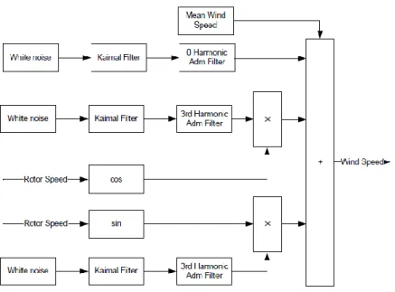
Figure 3-3: Harmonics filter method. Block Diagram [64]. ... 44
Figure 3-4: Physical topology of the permanent magnet induction generator [34] ... 48
Figure 3-5 Equivalent circuits of the induction generator and permanent magnet induction generator [34] ... 48
Figure 3-6: Physical topology of the slip synchronous induction generator [34]... 49
Figure 3-7: Equivalent circuit of the SSG [34]. ... 49
xii
Figure 3-10: Aerodynamic model implemented in Simulink... 52
Figure 3-11: Mechanical model implemented in Simulink... 53
Figure 3-12: High level hierarchy of the model implemented for the SSG in Simulink. ... 54
Figure 3-13: Model implemented in Simulink for the PM-rotor. ... 54
Figure 3-14: Model implemented in Simulink for the PMIG ... 55
Figure 3-15: Model implemented in Simulink for the PMSG. ... 55
Figure 3-16: Simulink tab showing the parameter set for the PMIG model. ... 56
Figure 3-17: Simulink tab showing the parameter set for the PMSG model. ... 56
Figure 3-18: Simulink tab for the parameter set of the PM rotor model... 56
Figure 3-19: Thevenin equivalent circuit of the grid network [68] ... 57
Figure 3-20: Simulink representation of the Thevenin equivalent grid network ... 57
Figure 3-21: Hierarchical overview of the grid-connected SSG model implementation in DigSILENT [73]. ... 58
Figure 3-22: DigSILENT DSL structure [61]. ... 59
Figure 3-23: DigSILENT DSL structure. [61] ... 59
Figure 3-24: Model implementation of the mechanical model in DSL. ... 60
Figure 3-25: DSL mechanical model implementation. ... 63
Figure 3-26: Common model parameters tab in DigSILENT. ... 64
Figure 3-27: Wind model implemented in DigSILENT. ... 66
Figure 3-28: Cross sectional view of the different synchronous generator types [31]. ... 68
Figure 3-29: Equivalent circuit and phasor diagrams for the classical synchronous machine [31] ... 69
Figure 3-30: Equivalent circuit diagram and phasor diagram for the synchronous machine [31]. ... 70
Figure 4-1: Simulated wind speed with the wind speed model implemented in DSL. ... 74
Figure 4-2: Simulated wind speed obtained with the wind model implemented in DSL using the power spectral density method. ... 75
Figure 4-3: Power spectral density of the simulated wind speed obtained with the wind model implemented in DSL using the power spectral density method. ... 75
Figure 4-4: Wind speed simulated with the wind model implemented in Simulink. ... 75
Figure 4-5: Power spectral density of the wind speed simulated with the wind model implemented in Simulink... 76
Figure 4-6: Simulated power coefficient as a function of tip speed ratio for different pitch angles. ... 78
Figure 4-7: Aerodynamic torque versus rotor speed characteristic simulated with the model implemented in DSL for different wind speeds and zero pitch angle... 78
Figure 4-8: Wind turbine characteristics at different wind speeds. ... 79
xiii
for the cases of when a mechanical drive train is integrated with the PMIG. ... 83
Figure 4-11: Simulation results of the turbine shaft speed in DigSILENT for constant mean wind speed. ... 84
Figure 4-12: Simulation results the mechanical power in DigSILENT. ... 84
Figure 4-13: Overview of the mechanical and electrical interaction of the turbine and the generator [80] ... 84
Figure 4-14: Generator speed and power response for steady state conditions in DigSILENT ... 85
Figure 4-15: Generator power response for steady state conditions in Simulink from mechanical torque input. ... 86
Figure 5-1: Per phase single line diagram representing the WEC and electrical network during faults. ... 88
Figure 5-2 : Simulation of results at the PCC: grid voltage, phase current, active and reactive power production duration of 100ms for 3-phase fault in Simulink ... 91
Figure 5-3:Simulation of results at the PCC: grid voltage, active and reactive power production duration of 100ms for single phase fault in Simulink... 92
Figure 5-4 PMSG wind turbine system subjected to grid faults at HV terminal ... 93
Figure 5-5 Single phase Thevenin equivalent circuit of the grid during a short circuit... 94
Figure 5-6: Simulation of results at the PCC: grid voltage, active and reactive power production duration of 100ms for 3-phase fault. ... 95
Figure 5-7 Simulation of results of PMSG: turbine mechanical torque production and generator speed for duration of fault. ... 96
Figure 5-8: Simulation of results at the PCC: grid voltage, active and reactive power production duration of 100ms for single phase fault ... 98
Figure C-1: Per-phase equivalent circuit of PMSG [80]... 115
Figure C-2: Per-phase equivalent modelling of a PMSG coupled directly to both the turbine and grid. ... 117
Figure E-1: Masked Simulink block of wind model representation. ... 120
Figure E-2: Simulink wind model masked parameter dialogue window. ... 120
Figure E-3: Simulink wind model design. ... 121
Figure E-4: Simulink wind model mask configuration window - Icon & Port. ... 121
Figure E-5: Simulink wind model mask configuration window - Parameters and Dialog tab. ... 122
Figure E-6: Simulink masked block of mechanical representation. ... 122
Figure E-7: Simulink mechanical model masked parameter dialogue window. ... 123
xiv
Figure E-10: Simulink mechanical model mask configuration window – parameters & Dialog. ... 124
Figure E-11: Simulink masked block of aerodynamic model representation ... 125
Figure E-12: Simulink aerodynamic model masked parameter dialogue window ... 125
Figure E-13: Simulink aerodynamic model design. ... 126
Figure E-14: Simulink aerodynamic model mask configuration window - Icon & Port. ... 126
Figure E-15: Simulink aerodynamic model mask configuration window - Parameters and Dialog tab. ... 127
Figure E-16: Masked Simulink block of grid network model representation. ... 132
Figure E-17: Simulink grid network model masked parameter dialogue window. ... 133
Figure E-18: Simulink grid network model design. ... 133
Figure E-19: Simulink grid network model mask configuration window - Icon & Port. ... 134
Figure E-20: Simulink grid network model mask configuration window – Parameters & Dialog ... 134
Figure E-21: Electrical equivalent circuit for the capacitor bank. ... 135
Figure E-22: Simulink design model for the capacitor bank. ... 136
Figure E-23: Simulink capacitor bank model masked parameter dialogue window. ... 136
Figure F-1: DigSILENT wind model design. ... 137
Figure F-2: DigSILENT common model for the wind model... 138
Figure F-3: DigSILENT aerodynamic model design. ... 140
Figure F-4: DigSILENT common model for the aerodynamic model... 140
Figure F-5: DigSILENT composite frame for Wind Turbine Plant (WTP). ... 141
Figure F-6: DigSILENT data manager showing the Grid elements common models for the wind turbine system (WTS). ... 142
Figure F-7: DigSILENT composite model for Wind Turbine Plant (WTP). ... 142
Figure G-1: single line diagram representing the SSG connected to grid. ... 143
xv
Table 1-1: Potential future wind capacity roll-out according to IRP 2010 and IRP 2013 [7]. ... 2
Table 2-1: International classifications of small wind systems [13]. ... 9
Table 2-2: Classification of wind turbine generators with reference to stall control, speed control and pitch control [31] ... 19
Table 2-3: RPP categories [39]. ... 25
Table 2-4: Voltage limits for different Independent Power Producers (IPP) categories [39] ... 26
Table 2-5: Disconnection times as a function of voltage variation [38] ... 28
Table 3-1: Input and output variable definitions of the wind model ... 44
Table 3-2: Parameter definitions of the wind model ... 44
Table 3-3: Turbine characteristic coefficients [71]. ... 46
Table 3-4: Input and output parameters for the mechanical model. ... 64
Table 3-5: Model parameters for the mechanical model. ... 64
Table 4-1: Look-up table used for the power coefficient for the aerodynamic model implemented in DSL. ... 77
Table A-1: SSG parameters. ... 110
Table D-1: The parameter values for the Kaimal spectrum constants. ... 119
Table F-1: DigSILENT inputs and outputs signals variables for the wind model design. ... 137
Table F-2: DigSILENT internal variables for wind model design. ... 137
Table F-3: DigSILENT inputs and outputs signals variables for the rotor model design. ... 139
Table F-4: DigSILENT internal variables for the rotor model design... 139
Table G-1: Slack bus parameters... 144
Table G-2: Grid transformer parameter values. ... 144
Table G-3: Collector cable parameters. ... 145
Table G-4: Generator transformer parameters. ... 145
xvi
Abbreviation Description
Eskom Electricity Supply Commission RE Renewable Energy
DEA Department of Environmental Affairs
UNFCCC United Nations Framework Convention on Climate Change IRP Integrated Resource Plan for electricity
GHG Greenhouse Gas
REFIT Renewable Energy Feed-In-Tariffs
NERSA National Energy Regulator of South Africa
REIPPP Renewable Energy Independent Power Producer Programme IPPPP Independent Power Producer Procurement Program
PV Photovoltaic
CSP Concentrating solar power IPP Independent Power Producers SSG Slip Synchronous Generator SWT Small Wind Turbine
AC Alternating Current DC Direct Current
IEC International Electrotechnical Commission NRCan Natural Resources Canada
CanWEA Canadian Wind Energy Association
REEEP Renewable Energy & Energy Efficiency Partnership BWE Bundesverband Wind Energie
MCS Micro-generation Certification Scheme AWEA American Wind Energy Association WTG Wind Turbine Generator
xvii
VAWT Vertical Axis Wind Turbines FS-FP Fixed-speed fixed-pitch FS-VP Fixed-speed variable-pitch VS-FP Variable-speed fixed pitch VS-VP Variable-speed variable-pitch SCIG Squirrel-Cage Induction Generator WRIG Wound Rotor Induction Generator DFIG Doubly Fed Induction Generator DFAG Doubly Fed Asynchronous Generator VSC Voltage-Source Converter
STATCOM Static Synchronous Compensator AVR Automatic Voltage Regulator
SS-PMG Slip Synchronous Permanent Magnet Generator SSG Slip Synchronous Generator
PMIG Permanent Magnet Induction Generator PMSG Permanent Magnet Synchronous Generator WECS Wind Energy Conversion System
PM Permanent Magnet
CSG Convectional Synchronous Generator RPP renewable power plant
MV Medium Voltage
LV Low Voltage
HV High Voltage
NSP Network Service Providers PCC Point of Common Coupling POC Point of Connection
xviii
IPP Independent Power Producers PFCC Power Factor Correction Capacitors AVR Automatic voltage regulator
WPP Wind power plant VRT Voltage Ride-Through LVRT Low Voltage Ride-Through HVRT High Voltage Ride-Through
NERC North American Electric Reliability Corporation ISO Independent System Operators
FACTS Flexible Alternating Current Transmission System CFCT Critical Fault Clearing Time
EMT Electromagnetic Transient Models DSL Dynamic Simulation Language
DigSILENT Digital SImuLator for Electrical NeTwork MATLAB Matrix Laboratory
GUI Graphical User Interface PSS power system stabilizer
xix
Parameter Description Unit
𝑣(𝑡) Wind speed ms-1
𝑣𝑓(𝑡) Low-frequency component wind speed ms-1
𝑣𝑚(𝑡) Turbulence component wind speed ms-1
𝑡𝑝 Time interval for instantaneous speed sec
A Swept area of wind turbine m2
Φ(𝜔) Kaimal spectrum 𝐾𝑣 Kaimal constant
𝜔 Rotor speed rad/s
𝑇𝑣 Kaimal constant
𝑃𝑤𝑡 Kinetic wind power W
𝑚̇ Mass flow rate kgs-1
𝑉𝑤 Wind speed ms-1
𝑝 Air density kgm-2
𝑅 Blade radius m
𝐶𝑃 Power coefficient p.u.
𝐶𝑄 Torque coefficient p.u.
𝜆 Tip speed ratio p.u.
𝜃𝑝𝑖𝑡𝑐ℎ. Pitch angle degrees
𝑇𝑡 Torque applied on the main shaft of the IG-rotor Nm
𝑇𝑟 IG electrical torque response Nm
𝑇𝑚 PM-rotor torque response, Nm
𝑇𝑠 SG electrical torque response Nm
𝜔 Angular velocity of the turbine rad/s
𝓃 Rotational speed rev/mi
xx
𝐽𝑚 Inertia of the IG-rotor and PM-rotor kg.m2 𝐵𝑚 PM-rotor viscous friction coefficient Nm/rad. s-1 𝐵𝑟 Slip-rotor viscous friction coefficient Nm/rad. s-1
𝐵𝑚𝑜 Slip-rotor static friction constant Nm
𝐶𝑖 Turbine’s characteristic coefficients p.u.
𝜔𝑡 Turbine’s spin speed rad/s
𝑖𝑞𝑟 IG q-axis current response A
𝑖𝑑𝑟 IG d-axis current response A
𝑅𝑟 IG resistance Ω
𝐿𝑞𝑟 IG q-axis inductance H
𝐿𝑑𝑟 IG d-axis inductance H
𝜔𝑠𝑙𝑒 Electrical slip speed rad/s
𝜆𝑚𝑟 IG PM flux-linkage Wb.t
𝑖𝑞𝑠 SG q-axis current response A
𝑖𝑑𝑠 SG d-axis current response A
𝑅𝑠 SG resistance Ω
𝐿𝑞𝑠 SG q-axis inductance H
𝐿𝑑𝑠 SG d-axis inductance H
𝜔𝑚𝑒 Electrical frequency at the stator terminals rad/s
𝜔𝑚 PM rotor speed rad/s
𝜆𝑚𝑠 SG PM flux-linkage Wb.t
𝑣𝑠 Voltage source V
𝐸𝑠 Induced voltage source V
𝐾𝑔𝑒𝑛 Generator constant 𝐾1 IG generator constant
xxi
𝑁2
IG per-phase number of turn’s turns
𝜙𝑃𝑀 PM flux T
𝑅2 IG per-phase resistance Ω
𝑓2
IG
per-phase frequency HzΦ2 IG flux per pole Wb
I2
IG per-phase
rotor current AE Induced electromotive force V
𝑈𝑠 Stator voltage V
𝑈ℎ Voltage representing the main field V
𝐼𝑠 Stator current A
𝑋𝑓 Field winding reactance Ω
𝑋ℎ Main reactance Ω
𝑋𝜎𝑠 The stator leakage reactance Ω
𝑅𝑠 Stator reactance Ω
Ѱ𝑃𝑀 Permanent magnet flux Wb
𝛿 Load angle rad
Ѱ𝐸 DC excited flux Wb
𝜑 Power factor p.u.
𝐼𝑓 Excitation current A
𝜔𝑔𝑒𝑛 Generator rotational speed. rad/s
m number of phases
𝑃𝑔𝑒𝑛 Generator active power W
𝑇𝑒 Electromagnetic torque Nm
𝑄𝑔𝑒𝑛 Generator reactive power VA
P number of pole pairs
xxii
𝑈𝑠𝑞 q-axis stator voltage V
𝑖𝑠𝑑 d-axis stator current A
𝑖𝑠𝑞 q-axis stator current A
𝜓𝑠𝑑 d-axis stator flux linkage Wb
𝜓𝑠𝑞 q-axis stator flux linkage Wb
𝐿𝑑 d-axis inductance H
𝐿𝑞 q-axis inductance H
𝑋𝑑 d-axis synchronous reactance Ω
𝑋𝑞 q-axis synchronous reactance Ω
𝑋𝑑′ d-axis transient reactance Ω
𝑋𝑞′ q-axis transient reactance Ω
𝑋𝑑′′ d-axis sub-transient reactance Ω
1
Chapter 1:
Project Motivation and Project Description
1.1 Introduction
The South Africa’s electrification program, with inclusion of the successful integration of renewable energy into the diverse electricity generation mix is founded in the Constitution (1996) and Bill of rights [1]. This is mandated in a number of key government policy papers, starting with the White Paper on Energy Policy of 1998 [2, 3]. Critical on the government agenda at the time was the mass rollout of electricity to people who were previously excluded from accessing energy services. The national electricity utility, Electricity Supply Commission (Eskom), however had excess capacity at the time and the development of renewable energy (RE) technology options were limited to a few demonstration or pilot projects wholly funded by the international donor community [2]. The second policy document on renewable energy, namely the Renewable Energy White Paper (2003) policy, set a target of 10 000 GWh of energy to be produced from renewable energy sources by 2013 [4]. The concluding section of this document recommended strategies on how to achieve the goals, but the drafting of such a document was not immediately undertaken [2].
The National Climate Change Response Policy White Paper of 2011 by the Department of Environmental Affairs (DEA) represents the final policy paper that supported the country’s renewable energy aspirations [5]. Cabinet, in 2008, adopted a peak, plateau and decline trajectory. This strategy was proposed to let the country’s emissions to grow up to a peak of around 550Mt CO2-eq between
2020 to 2025, flatten out for a decade, and decline from 2030-35 onwards, as shown in Figure 1-1. On a global scale the precedence was set with Kyoto protocol, an international agreement linked to the United Nations Framework Convention on Climate Change (UNFCCC), which commits its parties by setting internationally binding emission reduction targets [6].
In 2010, considering the plateau and decline scenarios shown in Figure 1-1 for carbon emissions, the Integrated Resource Plan for electricity (IRP, 2010) was established under the Electricity Regulation Act. The IRP was later redrafted in 2013 [7]. The IRP was established to weigh in decision making of national policy and to provide a planning framework to manage electricity demand for the period from 2010 to 2030. Table 1-1 summarises the future potential roll out of wind energy projects in the country considering the promulgated IRP 2010 and the updated draft IRP.
2
Figure 1-1: South Africa Greenhouse Gas (GHG) emission reductions and limits [8].
Table 1-1: Potential future wind capacity roll-out according to IRP 2010 and IRP 2013 [7].
Indicator IRP 2011 IRP 2013
MW MW
2030 Wind Power Target 9 100 (Excluding Sere wind farm)
4 360
REIPPPP Awarded (Round 1, 2, 3) 1 984 1 984
Total Capacity Remaining 7 116 2 376
Renewable Energy Feed-In-Tariffs (REFITs) where introduced in 2008 to incentivise the roll out of renewable energy on a large-scale. This structure was informed by international experience, as it has been widely used to encourage and accommodate renewable energy [2]. In 2011 the National Energy Regulator of South Africa (NERSA), after adjustments of the tariff policy, abolished the REFIT programme and opened a competitive bidding process for renewable energy, termed the Renewable Energy Independent Power Producer Programme (REIPPP). The REIPPP covers technologies identified in the IRP 2010, namely onshore wind, solar Photovoltaic (PV), solar Concentrating solar
3
power (CSP), biomass, biogas, landfill gas, and small hydro. After successful initial implementation of the REIPPP, the year of 2016 saw an unfortunate impasse in the installation of renewable energy capacity. As result, about 37 renewable energy projects did come to financial close, this included 12 wind farm projects. The REIPPPP had 5 bid windows in which 6 327 MW from 92 independent power producers (IPPs) were awarded. When the first 4 rounds of bidding completed, 34 projects were allocated to wind IPPs with a capacity of 3 357 MW [9, 10]. The success of the REIPPP is highly dependent on private sector investment [11].
Small Wind Turbines (SWT) require much higher capital costs in comparison to large wind turbines in order to achieve lower capacity factors. The SWT can however, contribute to meet electricity demands in remote areas, also provide local economic and social benefits particularly when utilised for off-grid electrification [12]. The deployment and development of small wind turbines is expanding, with a variety of sizes and styles having been developed. The horizontal axis wind turbines dominate the market (74% share of the market) [13], but face challenges of low turbulent wind speeds as they are generally located close to settlements where trees, buildings and other infrastructure is in the vicinity. Reliable performance under these conditions can be achieved with vertical-axis technologies, which can also operate with very low noise levels production [12].
1.2 Project motivation
The local power grid experiences constraints due to a relatively small margin between peak demand and the available generating capacity [14]. The nominal installed generation capacity is about 45,645MW, of which Eskom contributes approximately 95%, while the remainder comes from independent power producers (IPPs) and imports [14]. Plans are underway to diversify the electricity generation mix through the Independent Power Producer Procurement Program (IPPPP) [10]. The installed capacity currently consists of 85% of thermal power plants, 10% hydroelectric plants, 4% nuclear power plant, and 1% non-hydro renewable energy [14]. The renewable energy industry is therefore small, with ample scope for expansion.
Many remote areas in the world are not connected to an electrical grid and, if connected, the load is connected through weak distribution grids. Small wind generators have potential for electrification of these remote areas, thereby mitigating the need for expensive transmission system infrastructure. Embedded systems or distributed systems, furthermore, reduce system losses [15], as the point of generation is connected close to the load. This also assists in maintaining system stability.
The world market for small wind technologies is growing. As of the end of 2015, the cumulative total of installed capacity worldwide has reached more than 948 MW, which represents an increase of 14%
4
compared to the 803 MW recorded in 2014. The industry of small wind technologies is, however, in its infancy stage. Three countries dominate in small wind power generation which are, namely China, USA and UK [13]. Figure 1-2 shows some the installed capacity of small wind technologies by country and Figure 1-3 shows the number of cumulative units installed as of end of 2015.
Figure 1-2: Installed small wind technology capacities by country [16]
Figure 1-3: Installed number of small wind technology units by country [16]
The installed wind energy capacity in South Africa, after being stagnant since 2002 when the first 10 MW installation of wind power occurred, peaked to a cumulative capacity of 1471 MW by the end of 2016 [17]. Figure 1-4 shows the growth of installed wind generation capacity. This is expected to
5
expand due to the REIPPP, which presently has more than 3365 MW under different developmental stages.
Figure 1-4: Total installed wind energy capacity of South Africa [17].
The Slip Synchronous Generator (SSG), currently being developed, represents one of the new concept small generators with potential for wind energy applications. It is both directly coupled to the turbine and the distribution grid network, hence reducing the downtime typically caused by gearbox and power electronic converter failures [18, 19, 20, 21]. This research project investigates the performance of the SSG machine for wind generation applications when tied to weak rural distribution grids. 1.3 Project description
1.3.1 Overview
The project investigates the performance of an embedded direct driven SSG in weak electrical grids and the grid interaction behaviour for transient stability analysis of the distribution network under fault conditions. This remainder of this section highlights the key research questions, research objectives and research tasks pertaining to the investigation. In order to investigate the steady-state and dynamic performance of the embedded SSG, a case study is carried out for a benchmarked grid network representing a weak grid network as a Thevenin equivalent circuit. The investigation considers the effects on network stability during single and three-phase faults.
0 200 400 600 800 1000 1200 1400 1600 2002 2003 2004 2005 2006 2007 2008 2009 2010 2011 2012 2013 2014 2015 2016 MW 3.16 3.16 3.16 3.16 3.16 3.16 8.36 8.36 10.16 10.16 10.16 10.16 570 1053 1471 In st al le d c ap ac it y [M W] year
6
1.3.2 Project objectives
The project involves implementation of a dynamic model of an SSG in both the MATLAB/Simulink and DigSILENT platform, then the simulation and analysis of the behaviour of the embedded wind generator when tied to weak electrical distribution grids. Transient network analysis is conducted to show how the system grid interaction is impacted when there is a transient fault on the grid network. The following research objectives have been identified for the project:
The development and implementation of a dynamic model of the SSG in Matlab/Simulink. Analysing the effects of changing wind conditions on the behaviour of the SSG.
The development and implementation of a dynamic model of the SSG in DigSILENT
Comparing simulated dynamic model responses obtained with Matlab/Simulink to those obtained with DigSILENT.
Conducting a case study of the SSG connected in a weak network with the view to investigate the effects on grid stability.
1.3.3 Research questions
The project objectives give rise to the following research questions:
What analytical software is suitable to study the effects of embedded wind generation on weak remote distribution grids?
Which software platform performs the best for modelling the system performance for normal, fault and switching conditions?
How does the SSG perform in weak rural/remote grids with reference to the following?
System stability
Low Voltage Ride Through (LVRT) during grid faults 1.3.4 Research tasks
The research tasks implemented for the thesis are as follows:
Perform a literature review of the technologies pertaining to small wind energy conservative system.
Implement a dynamic model of the SSG in Matlab/Simulink and test the model implementation for dynamic scenarios.
7
Implement a dynamic model of the SSG in DigSILENT and compare the performance of the model implementation with the results obtained with the model implemented in Matlab/Simulink Model a benchmark network topology for weak distributed systems.
Perform case studies of the dynamic performance of the SSG for a typical rural network. 1.4 Overview of report
The remainder of the document is structured as follows: Chapter 2: Literature review:
This section explores the definition of a small wind turbine and considers the classification of wind turbine systems, especially with reference to their behaviour when connected to the grid. The network grid code for renewable energy in South Africa is outlined, especially in the context of embedded systems. Lastly, the nature and characteristics of weak networks are described and the available software tools for analysing the case studies are reviewed.
Chapter 3: Model development and implementation:
This section focusses on the development of the mechanical model, control model and the fixed speed SSG wind turbine dynamic model on the Matlab/Simulink and DigSILENT platforms. The mechanical model consists of the wind resource, aerodynamic model and drive train with a fixed pitch stall control acting on the blade turbines. The theory of the SSG`s steady state and dynamic behaviour during normal, fault and switching conditions is introduced.
Chapter 4: Simulated model performances:
Simulation results are presented for a case study of the SSG for a distribution network characterised by a weak electrical grid network in the DigSILENT and Matlab/Simulink platforms.
Chapter 5: Case studies results:
Simulated results are presented for the dynamic performance of the SSG turbine system in the case study network.
Chapter 6: Conclusions and recommendations
8
Chapter 2:
Literature review
2.1 Overview
Wind energy systems which are now currently classified as big or in some instances large wind systems evolved from what is today referred to as small wind systems [13]. In the pioneering stages wind turbines mostly had capacities of less than 100 kW and were located predominantly in remote isolated areas [12].
There is still no definitive globally unified definition of small wind systems. Small wind systems were originally defined in the context of producing small amounts of power to mainly supply residential sector loads. However, this definition varies in the global context, as the associated power consumption patterns are unique in the different parts of the world [13].
Technically, a variety of definitions for Small Wind Turbines (SWTs) are available, as summarised in Table 2-1. One of these definitions, as covered by the IEC, defines a SWT in standard IEC 61400-2 as “having a rotor swept area of less than 200 m2, which typically equates to a rated power of
approximately 50 kW generating at a voltage level below 1000 V AC or 1500 V DC. In addition to this definition, several countries have proposed their own definitions of small wind systems [13].” The various definitions of the upper capacity limit of small wind ranges between 15kW to 100 kW for the five largest small wind countries [13]. The modern definition of upper limit capacity leans towards 100 kW, mainly due to the definition prevalent in the North American and European markets. This is the definition adopted for the purposes of this investigation. For the purposes of standardisation, however, it is important that a common definition of small wind should be agreed upon in the longer term.
9
Table 2-1: International classifications of small wind systems [13]. Authority/Association Turbine Classification Rated Capacity [W] Remarks Int e rna ti on a l International Electrotechnical Commission (IEC) Small Wind Turbine
≈50 IEC 61400-2 defines SWTs as having a rotor swept area of less than 200 m2,
rated power of approximately 50 kW, voltage below 1’000 V AC or 1’500 V DC Ca na da Natural Resources Canada (NRCan)Canadian Wind Energy Association (CanWEA) Mini Wind Turbine
0.3-1 Adopted in the Survey of the Small Wind by Marbek Resource Consultants Small Wind
Turbine
1-30
Chi
na
Renewable Energy & Energy Efficiency Partnership (REEEP)
Small Wind Turbine
<100 Adopted in the recent National Policy, Strategy and Roadmap Study for China Small Wind Power
Industry Development G e rm a ny Bundesverband WindEnergie (BWE) Small Wind Turbine
<75 Adopted in the recent
BWE-Marktübersicht spezial – Kleinwindanlagen U ni te d K ingdo m
Renewable UK Micro Wind 0 – 0.15 0,5-5 m Height / Up to 1’000 kWh Annual Energy Production
Small Wind 1.5 – 15 2-50 m Height / Up to 50’000 kWh Annual Energy Production
Small-medium Wind
15 – 100 50-250 m Height / Up to 200’000 kWh Annual Energy Production
Microgeneration Certification Scheme (MCS)
Micro & Small Wind
Turbine
<50 Only turbines smaller than 50 kW qualify for the MCS feed-in tariff programme in UK
USA
American Wind Energy Association (AWEA)
Small Wind Turbine
<100 Adopted in the most recent
AWEA Small Wind Report 2010 and the AWEA Small Wind Turbine Global Market Study
10
2.2 Wind maps
Wind speed is an exogenous input signal applied to a Wind Energy Conversion System (WECS) that determines its behaviour. The stochastic variation of wind speed is highly dependent on the given site and on atmospheric conditions. Figure 2-1 shows a map of the mean wind speed for South Africa. It represents possible appealing geographical areas where wind power generation farms have a potential to be installed. It’s more appealing to install the wind turbine system close to or at coastal regions as they are characterised by strong wind speeds.
Figure 2-1: South Africa mean wind speed [ms-1] at a height of 100 m [22].
2.3 Wind turbine classification 2.3.1 Overview
A wind turbine system converts the kinetic energy of a moving mass of air into mechanical energy. This is achieved by using aerodynamic rotor blades combined with various methodologies for mechanical power control. This is followed by the electro-mechanical energy conversion using a generator, which is tied to the electrical grid for power transmission [15].
11
Wind turbines can be installed onshore or offshore. Before the early 2000's, wind power was predominantly harnessed by onshore wind farms. The onshore wind system is generally preferred as it represents the cheaper option that requires less infrastructure and less advanced and specialized technology compared to the offshore option. The drawback in optimization of onshore wind turbines is the stochastic nature of wind speeds over land. Wind turbines are characterised by inefficiencies, since they can be only optimized for a specific wind speed, while wind speed and wind direction exhibit large variability. Many of the problems that hinder onshore wind systems are greatly alleviated in offshore farms. Wind speeds over the ocean are typically more consistent and much higher compared to onshore wind speeds. Offshore wind turbines can therefore be optimized to operate at high efficiencies. There is a public dislike for onshore wind turbines marring landscapes, which makes offshore wind appealing. Most of the large cities, furthermore, tend to be located near shorelines, thus avoiding the expense of transmitting power over long distances associated with offshore wind farms. Offshore wind farms are, however, considerably more expensive to design, build, install and maintain. Onshore technologies can be either connected on the upwind or downwind direction. Upwind turbines, which are the most popular design, have the rotor facing the wind thereby making the design able to avoid the wind shade introduced by the tower. However, the wind shade in front of the tower cannot be eliminated, even if the tower is round and smooth. The upwind machine needs a yaw mechanism to keep the blades facing the wind and the blades need to rather inflexible and positioned at some distance from the tower [23]. Downwind turbines have the blades on the lee side of the tower. They may be designed without a yaw mechanism, if the rotor and nacelle have a design that can make the nacelle follow the wind passively. In this design the rotor may be made more flexible and the structural dynamics of the machine may thus be lighter than compared to an upwind machine. The drawback is that it may give rise to more fatigue loading on the turbine compared to an upwind design. This results from fluctuation in wind power due to the rotor passing through the wind shade of the tower [23].
2.3.2 Horizontal- and vertical- axis wind turbines
Wind turbines are classified into two generic types, namely Horizontal Axis Wind Turbines (HAWT) and Vertical Axis Wind Turbines (VAWT), based on the orientation of their spin axis. A horizontal axis machine has its blades rotating on an axis parallel to the ground. A vertical axis machine has its blades rotating on an axis perpendicular to the ground. Figure 2-2 illustrates the blade orientations of horizontal-axis and vertical-axis wind turbines.
12
There are advantages and disadvantages for each of these designs. However, compared with the horizontal axis type, very few vertical axis machines are available commercially [24]. The advantages of the HAWT system include high turbine efficiency, high power density, low-cut-in wind speeds and low cost per unit power output. The main advantage of the VAWT system is that it can accept wind from any direction, so that yaw control is not necessary. The drawbacks of the VAWT system are that the turbine system needs an external energy source to rotate the blade during start-up and that the maximum practical height that the turbine can reach is limited because the axis of the wind turbine is supported only on one end at the ground.
Wind turbines can be categorised further by their mechanical power and speed control mechanisms. The turbine blades draw and convert the motion of air to torque, and the torque is regulated to optimise energy capture whilst preventing damage in the process [25].
Figure 2-2: Blade orientations of horizontal-axis and vertical-axis wind turbines [24].
2.3.3 Speed control of wind turbines
The power output of the wind turbine system can be either optimised or limited through the use of different control methods. These control principles include pitch angle and yaw control, which are illustrated in Figure 2-3. Pitch angle control adjusts the blades to alter the wind turbine speed, thereby controlling the generator speed. The objective of this control is to optimise the blade angle in order to control the output power for wind speeds more than the rated value. Yaw control continuously alters the orientation of the entire wind turbine to ensure that the turbine is consistently facing into the wind to maximise the effective swept area. This increases the amount of energy captured and thus yields a high output power as a result. The drawback is that, due to the intermittent nature of wind, wind
13
direction can change rapidly, and the turbine may misalign with the wind direction, thereby causing a loss of power.
(a) (b)
Figure 2-3: Definition of (a) pitch angle and (b) yaw rotation [26]
The most common speed and pitch control strategies can be classified as follows: Fixed-speed fixed-pitch (FS-FP):
Fixed-speed fixed-pitch stall control regulation involves reducing the turbine’s torque by altering the pitch of the turbine blades such that the air foil generates less aerodynamic force at high wind speed, until stalling. It is a simple, inexpensive and robust mechanical system. The generator is directly coupled to the power grid, and as a result the generator speed is synchronous to the power line frequency.
Fixed-speed variable-pitch (FS-VP):
Fixed-speed variable-pitch control enables the wind turbine system to generate output power at fixed speed. Active stall regulation uses both the blade and stall pitch control methods to limit the power, as illustrated in Figure 2-4 . Below the rated speed, the FS-VP turbine has an optimum efficiency around region II. When the rated wind speed is exceeded, the pitch angle is altered constantly.
14
Variable-speed fixed pitch control utilises passive stalling to achieve a fixed pitch and has the generator indirectly tied to the grid to enable the generator`s rotor and drive train to rotate independently from the grid network frequency.
Variable-speed variable-pitch (VS-VP):
Variable-speed variable-pitch control is used to maximise the energy capture and to be able to increase the power when the turbine wind system is operating below the rated wind speed as illustrated in Figure 2-4 . When the wind speed exceeds the rated wind speed, the variable-speed and variable-pitch control allows efficient power regulation at rated power.
Figure 2-4: Wind turbine output power characteristics and wind speed regions [26] 2.3.4 Fixed and Variable speed wind turbines
A typical wind turbine system is comprised of an aerodynamic rotor that drives a low-speed shaft coupled to high-speed shaft via a gearbox, with the output shaft driving a generator. The fixed speed wind turbine system has its asynchronous generator generating power at a fixed rotational speed at different wind speed ranges. This type of wind turbine is directly coupled to the grid network through a transformer and the operating range of rotational speed of the generator is limited, not to exceed 1% to 2% of the nominal value.
The rotational speed of the variable speed wind turbine generator is variable, and the generator has the ability to generate power at different rotational speeds. The generator is not limited to only asynchronous generators, as some typical types include synchronous and permanent magnet type generators. The turbine is indirectly connected to the grid through power converters.
15
Wind turbines systems are further categorised according to the associated generator topology, including the following: fixed speed (Type 1); limited variable speed (Type 2); or variable speed with either partial (Type 3) or full power electronic conversion (Type 4); or a synchronous machine directly tied to the grid and with a mechanical torque converter between the rotor’s low-speed shaft and the generator’s high-speed shaft to maintain the generator speed at the electrical synchronous speed (Type 5) [15].
2.3.4.1 Type 1 wind turbine generator topology
The Type 1 Wind Turbine Generator (WTG) topology, shown in Figure 2-5 , incorporates a Squirrel-Cage Induction Generator (SCIG) that is connected directly to the step-up transformer. This is the most widely used and conventional wind turbine scheme. The topology is a stall or active stall controlled system with an aerodynamic rotor that couples via a gearbox to the SCIG. The turbine speed is determined by the grid network frequency. It is sometimes referred to as ‘Danish concept’, because it was developed and widely used in Danish wind turbines. Figure 2-6 illustrates the power flow characteristics at the SCIG terminals. While there is a bit of variability in output power with the slip of the machine, Type 1 turbines usually operate at or very close to a rated speed. The main disadvantage of induction machine is that it draws a lot of reactive power for excitation. Large currents are draw when the machine is started online. To improve these effects the turbine typically is coupled through a soft starter and is operated with discrete steps of capacitor banks [27].
16
Figure 2-6:Variation of real and reactive power for the Type I WTG topology [15].
2.3.4.2 Type 2 wind turbine generator topology
The Type 2 WTG topology, shown in Figure 2-7 , incorporates a Wound Rotor Induction Generator (WRIG) with connections which are similar to the Type 1 turbine system with regards to its stator circuit. It does, however, incorporate an external variable rotor resistance. This arrangement is accomplished with a set of resistors and power electronics external to the rotor with currents flowing between the resistors and rotor via slip rings [27]. With a resistance in the rotor circuit, the active power curve can in be extended to the higher slip and higher speed ranges as shown in Figure 2-8. This in implies that the turbine would have to spin faster to create the same output power. To facilitate an efficient capture of energy the machine must have the ability to control the speed This usually implemented by the blade pitching mechanism. Typical speed variations of up to 10% are possible, which gives allowances for some degree of freedom in energy capture and self-protective torque control [15].
17
Figure 2-8:Variation of real and reactive power for the Type 2 WTG topology [15].
2.3.4.3 Type 3 wind turbine generator topology
The Type 3 WTG topology, shown in Figure 2-9, incorporates a Doubly Fed Induction Generator (DFIG), also known as Doubly Fed Asynchronous Generator (DFAG). This is a modification of the Type 2 topology design where a variable frequency ac excitation system is utilised rather than simply using an external resistance in the rotor circuit. The rotor excitation is supplied through slip rings using a current regulated voltage-source converter (VSC) that can instantaneously adjust the magnitude and phase of the rotor currents. The active power is feed to the grid to the grid through a converter connected back-to-back to a rotor-side converter as shown [29].
A great deal of control of the output power can be achieved through the set of converters, which are mostly rated at only 30% of the rating of the machine. This control ability is possible since a small amount power injected into the rotor circuit can affect a large control of power in the stator circuit. The DFIG real power can be delivered to the grid from the generator’s stator circuit, and also delivered to the grid through the grid-connected inverter when the generator speed is above synchronous speed. When the generator speed is below synchronous speed, real power flows from the grid, via both converters, and from rotor to stator. These two modes, which is enable by the four-quadrant nature of the two electronic converters, makes it possible for a wider speed range of up to 50% both above and below synchronous speed, although narrower ranges are more common in practice.
The greatest advantage of the DFIG is that, just like convectional synchronous generators, it offers the benefits of separate real and reactive power control while being able to run asynchronously. Using the concepts of vector or field-oriented control of induction machine control schemes, the torque
18
producing components of the rotor flux can be made to respond fast enough so that the machine remains under relative control, even during significant grid disturbances. While more expensive than the Type 1 or 2 machines, the Type 3 is becoming popular due to its advantages [27].
Figure 2-9: Type III wind turbine generator topology [30, 31].
2.3.4.4 Type 4 wind turbine generator topology
The Type 4 turbine wind turbine generator topology, shown in Figure 2-10 enables a great deal of flexibility in design and operation as the output of the rotating machine is connected to the grid through an electrical interface of a full-scale back-to-back frequency converter [27]. The turbine can rotate at its optimal aerodynamic speed, resulting in a variable output power from the machine. The generator can optionally be an asynchronous or synchronous generator. Figure 2-11 shows a modification of this topology [31]. The gearbox may be eliminated, usually when implementing a synchronous generator instead of an induction generator, such that the machine rotates at the slow turbine speed and generates an electrical frequency well below that of the grid frequency. This is no problem for a Type 4 turbine, as the inverters convert the power, and offer the possibility of reactive power supply to the grid, much like a Static Synchronous Compensator (STATCOM). The synchronous generator is electrically excited through a Direct Current (DC) system or by means of a permanent magnet.
19
Figure 2-11: Variation of the Type IV wind turbine generator topology [28, 31, 27]
Table 2-2 shows a brief summary of the WTG topology classifications. It represents an alternative classification of wind turbine systems with the type ranging from type A to D rather than as represented in the above sections which ranges from type 1 to 4.
Table 2-2: Classification of wind turbine generators with reference to stall control, speed control and pitch control [31]
2.3.4.5 Type 5 WTG topology
The Type 5 turbine wind turbine generator topology, shown in Figure 2-12, makes use of a typical variable-speed wind turbine with its drive train connected to a torque/speed converter coupled to a synchronous generator [15].The variable speed is controlled by the torque/speed converter to a fixed speed determined by the grid frequency. The machine is connected to the network through a synchronizing circuit breaker. The synchronous generator can be implemented for any desired speed ranges and voltage levels. This approach requires speed and torque control of the torque/speed
20
converter along with the typical Automatic Voltage Regulator (AVR), synchronizing system, and generator protection system along with a grid-connected synchronous generator.
Figure 2-12: Type V wind turbine generator topology [15].
2.3.4.6 Generator concepts under development
The newest trend of wind turbine technology focuses on direct driven and direct grid coupled wind turbines, which employs a gearless drive train and without any power electronic converter [32] . One such type is the Slip Synchronous Permanent Magnet Generator (SS-PMG) topology also known as Slip Synchronous Generator (SSG), shown in Figure 2-13.
It can be described as a hybrid WTG design, which incorporates both the beneficial aspects of Permanent Magnet Induction Generator (PMIG) and Permanent Magnet Synchronous Generator (PMSG) [33, 20] . This evolutionary Wind Energy Conversion System (WECS) implements neither a gearbox nor a frequency converter as shown in Figure 2-13. The SSG is driven directly by a fixed speed wind turbine and is coupled directly to the grid through a grid synchronisation controller [33]. The SSG utilise a two-permanent magnet (PM) generators mechanically linked by a common PM rotor. The turbine and slip-rotor are mechanically linked and rotate in unison. The PM-rotor can rotate freely, without any mechanical connection to the other components. The slip-rotor can be implemented as either a short-circuited wound rotor or as a cage rotor. Together with the corresponding half of the PM-rotor, it constitutes a short-circuited PMSG, which develops substantial torque as soon as there is relative motion between the two rotors [20].
The second half of the PM-rotor couples with the stator to form a grid-connected PMSG. This side of the machine is driven indirectly by the torque from the wind turbine, which is transmitted through the first slip-rotor stage. The advantage of this connection is that it introduces damping and allows for some rotational speed difference between the turbine and the PM-rotor. There are effectively three
21
masses, namely the turbine and slip-rotor, the PM-rotor and the grid-connected stator. Although the connection between the PM-rotor and the stator is lightly damped, it is possible to avoid oscillations in this connection by making it substantially stiffer than the connection between the slip-rotor and the PM-rotor [33, 20]. If the slip-rotor to PM-rotor connection is less stiff, any disturbances will cause an oscillation to develop between these two masses (in this case the PM-rotor and stator effectively form a single mass). Any such oscillations will be attenuated quickly because the slip-rotor to PM-rotor connection is sufficiently damped. As a result, the SS-PMG will be able to remain connected to the grid in a stable manner, despite torque disturbances from wind gusts and tower shadow effects [33]. An additional advantage of the SSG design is that the turbine speed can vary by approximately 5 %, even while the PM-rotor speed is effectively fixed at synchronous speed. This means that the energy present in a wind gust can be captured as an increase in the rotational kinetic energy of the turbine and slip-rotor. This energy can then be delivered in a more gradual manner to the grid, without imposing harsh mechanical loads on the turbine or injecting a current spike on to the network. Like the torque filtering described above, this behaviour is inherent to the SSG and requires no control intervention to take place.
The characteristics of the SSG show a strong resemblance to those of a grid connected IG. The SSG is, however, superior to an Induction Generator (IG) in terms of its grid support capabilities. Since it is a direct-to-grid synchronous generator, the SSG contributes positively towards network inertia and provides natural grid voltage support by supplying reactive power whenever the network voltage drops.
(a) (b)
Figure 2-13: Slip Synchronous Permanent Magnet Generator wind turbine generator topology (a) connected to the grid and (b) Cross-section of the conceptual SS-PMG layout [33]
.
In a permanent magnet induction generator, a relative of the SS-PMG, can be connected to the grid in two ways [34]. In the first case, the PMIG is switched on to the grid from standstill, which results in
![Figure 1-3: Installed number of small wind technology units by country [16]](https://thumb-us.123doks.com/thumbv2/123dok_us/10959162.2984252/27.892.132.777.649.949/figure-installed-number-small-wind-technology-units-country.webp)
![Figure 2-1: South Africa mean wind speed [ms -1 ] at a height of 100 m [22].](https://thumb-us.123doks.com/thumbv2/123dok_us/10959162.2984252/33.892.174.737.356.768/figure-south-africa-mean-wind-speed-ms-height.webp)
![Figure 2-6: Variation of real and reactive power for the Type I WTG topology [15].](https://thumb-us.123doks.com/thumbv2/123dok_us/10959162.2984252/39.892.305.641.151.378/figure-variation-real-reactive-power-type-wtg-topology.webp)
![Figure 2-8: Variation of real and reactive power for the Type 2 WTG topology [15].](https://thumb-us.123doks.com/thumbv2/123dok_us/10959162.2984252/40.892.277.638.149.396/figure-variation-real-reactive-power-type-wtg-topology.webp)
![Figure 2-14: Minimum frequency operating range of a RPP during frequency disturbance [39]](https://thumb-us.123doks.com/thumbv2/123dok_us/10959162.2984252/49.892.166.754.163.461/figure-minimum-frequency-operating-range-rpp-frequency-disturbance.webp)
![Figure 2-15: Voltage ride through capability for RPPs of category A1 and A2 [39].](https://thumb-us.123doks.com/thumbv2/123dok_us/10959162.2984252/50.892.141.786.139.432/figure-voltage-ride-capability-rpps-category-a-a.webp)
![Figure 2-17: Requirements for Reactive Power Support, IQ, during voltage drops or peaks at the Point of Connection (POC) [39]](https://thumb-us.123doks.com/thumbv2/123dok_us/10959162.2984252/51.892.321.596.145.497/figure-requirements-reactive-power-support-voltage-point-connection.webp)
![Figure 2-18: Reactive power requirements for RPPs of category B (left) and C (right) [39]](https://thumb-us.123doks.com/thumbv2/123dok_us/10959162.2984252/52.892.136.819.678.963/figure-reactive-power-requirements-rpps-category-left-right.webp)
![Figure 3-2: The Van der Hoven spectrum model of wind speed [65]](https://thumb-us.123doks.com/thumbv2/123dok_us/10959162.2984252/65.892.194.736.417.933/figure-van-der-hoven-spectrum-model-wind-speed.webp)