in Multiple Antenna Wireless
Communication Systems
by
Jawad Mirza
A thesis
submitted to the Victoria University of Wellington in fulfilment of the
requirements for the degree of Doctor of Philosophy
in Engineering.
Victoria University of Wellington 2015
Acknowledgments
Firstly, I would like to thank Almighty “Allah” for giving me strength and wis-dom throughout my life.I would like to express my sincere appreciation to my supervisors Dr. Pawel Dmochowski and Prof. Mansoor Shafi. I am very grateful to Pawel for his continuous support and encouragement throughout my research. He provided me with opportunities and dedicated invaluable time to this research work. I also have been truly fortunate to be one of the students of Prof. Mansoor Shafi, who always guided my research towards the right direction. More than anything else, he has taught me how to be a thoughtful person.
I am also grateful to Prof. Peter Smith for providing valuable technical and non-technical suggestions to improve my research work. He has always been there to answer my innumerable questions related to the research and his will-ingness to solve the problems analytically is very inspiring. I would also like to thank Dr. Abdulla Firag and Dr. Min Zhang for helping me to understand some critical concepts at the start of my PhD. Sincere appreciation also goes to Dr. Paul Teal, Dr. Alan J. Coulson and Dr. Vasanthan Raghavan for examining the thesis and providing useful suggestions.
I am very grateful to have had the chance to share this journey with extraordi-nary friends and amazing colleagues. I am thankful to their presence, support and guidance. I want to thank Muhammad Adeel Mahmood, Saqib Saleem, Harsh Tataria, Ramoni O. Adeogun, Saud Naqvi, Afraz Liaquat, Tahir Suleman, Asim Masood, Abdul Wahid, Muhammad Ibrahim, Mudassir Altaf, Muhammad Iqbal, Refik Fatih Ustok, Callum Neil and Ahmed Sheik Deeb.
Finally, I would like to express my deepest gratitude to my family for their unconditional love, support and sacrifice. I would like to thank my parents for teaching me the value of education, patience and perseverance. I would like to thank my sisters for showering me with affection and for encouraging me. I am greatly indebted to my brother and best friend Ammar. I am sincerely grateful to my wife for her cooperation and support. Last but not least, I dedicate this work to my beautiful daughter Ayra, whom I love and adore.
Abstract
Multiple antenna systems provide spatial multiplexing and diversity benefits. These systems also offer beamforming and interference mitigation capabilities in single-user (SU) and multi-user (MU) scenarios, respectively. Although diver-sity can be achieved without channel state information (CSI) at the transmitter using space-time codes, the knowledge of instantaneous CSI at the transmit-ter is essential to the above mentioned gains. In frequency division duplexing (FDD) systems, limited feedback techniques are employed to obtain CSI at the transmitter from the receiver using a low-rate link. As a consequence, CSI ac-quired by the transmitter in such manner have errors due to channel estimation and codebook quantization at the receiver, resulting in performance degrada-tion of multi-antenna systems. In this thesis, we examine CSI inaccuracies due to codebook quantization errors and investigate several other aspects of limited feedback in SU, MU and multicell wireless communication systems with various channel models.
For SU multiple-input multiple-output (MIMO) systems, we examine the capac-ity loss using standard codebooks. In particular, we consider single-stream and two-stream MIMO transmissions and derive capacity loss expressions in terms of minimum squared chordal distance for various MIMO receivers. Through simulations, we investigate the impact of codebook quantization errors on the capacity performance in uncorrelated Rayleigh, spatially correlated Rayleigh and standardized MIMO channels. This work motivates the need of effective codebook design to reduce the codebook quantization errors in correlated chan-nels.
Subsequently, we explore the improvements in the design of codebooks in tem-porally and spatially correlated channels for MU multiple-input single-output (MISO) systems, by employing scaling and rotation techniques. These code-books quantize instantaneous channel direction information (CDI) and are re-ferred as differential codebooks in the thesis. We also propose various adaptive scaling techniques for differential codebooks where packing density of codewords
iv
in the differential codebook are altered according to the channel condition, in order to reduce the quantization errors. The proposed differential codebooks improve the spectral efficiency of the system by minimizing the codebook quan-tization errors in spatially and temporally correlated channels.
Later, we broaden the scope to massive MISO systems and propose trellis coded quantization (TCQ) schemes to quantize CDI. Unlike conventional codebook approach, the TCQ scheme does not require exhaustive search to select an appropriate codeword, thus reducing computational complexity and memory requirement at the receiver. The proposed TCQ schemes yield significant per-formance improvements compared to the existing TCQ based limited feedback schemes in both temporally and spatially correlated channels.
Finally, we investigate interference coordination for multicell MU MISO systems using regularized zero-forcing (RZF) precoding. We consider random vector quantization (RVQ) codebooks and uncorrelated Rayleigh channels. We derive expected SINR approximations for perfect CDI and RVQ codebook-based CDI. We also propose an adaptive bit allocation scheme which aims to minimize the network interference and moreover, improves the spectral efficiency compared to equal bit allocation and coordinated zero-forcing (ZF) based adaptive bit allocation schemes.
Acronyms
3GPP 3rd Generation Partnership ProjectAoA Angle of Arrival
AoD Angle of Departure
BER Bit error rate
BS Base Station
CDF Cumulative Distribution Function
CDI Channel Direction Information
CF Characteristic Function
CIR Channel Impulse Response
CSI Channel State Information
DoF Degree of Freedom
EC Ergodic Capacity
ECL Ergodic Capacity Loss
FDD Frequency Division Duplexing
FOGM First-Order Gauss-Markov
vi
i.i.d. Independent and Identically Distributed
ICI Inter-Cell Interference
IMT International Mobile Telecommunications
ITU International Telecommunication Union
IUI Inter-User Interference
JP Joint Processing
KKT Karush–Kuhn–Tucker
LoS Line-of-Sight
LTE Long Term Evolution
MF Matched-Filter
MIMO Multiple-Input-Multiple-Output
MISO Multiple-Input-Single-Output
MMSE Minimum-Mean Squared Error
mmWave Millimeter Wave
MU Multi-user
HetNet Heterogeneous Network
NLoS Non-Line-of-Sight
NTCQ Non Coherent Trellis Coded Quantization
O2I Outdoor-to-Indoor
PDF Probability Density Function
RMa Rural Macro
RVQ Random Vector Quantization
RZF Regularized Zero-Forcing
SCM Spatial Channel Model
SCME Spatial Channel Model Extended
SIMO Single-Input-Multiple-Output
SINR Signal-to-Interference-Plus-Noise Ratio
SISO Single-Input-Single-Output
SLNR Signal-to-Leakage-Plus-Noise Ratio
SMa Sub-urban Macro
SNR Signal-to-Noise Ratio
SU Single-user
SVD Singular Value Decomposition
TCQ Trellis Coded Quantization
TDD Time Division Duplexing
ULA Uniform linear array
UMa Urban Macro
UMi Urban Micro
viii
WINNER Wireless World Initiative New Radio
Notation and Symbols
N(µ, σ2) Normal distribution with mean µand variance σ2
CN(µ, σ2) Complex normal distribution with mean µand variance σ2
R+ Set of positive real numbers
Z+ Set of positive integers
| · | Absolute value
k · k Euclidean norm of a vector
k · kF Frobenius norm of a matrix
E [ · ] Expected value
det(·) Determinant of a matrix tr(·) Trace of a matrix
log2(·) Logarithm to the base 2 log10(·) Logarithm to the base 10
ln(·) Natural logarithm e(·) Exponential function
β(·,·) Beta function
x
L(·,·) Lagrange function
SVD(·) Singular value decomposition Ei(·,·) Generalized exponential integral Γ(·,·) Incomplete gamma function (·)T Matrix or vector transpose
(·)⊥ Null space of a vector
(·)−1 Inverse of a Matrix
(·)H Conjugate transpose of a matrix and a vector
(·)+ max(·,0)
ℜ(·) Real part of a complex number
ℑ(·) Imaginary part of a complex number
⌊x⌋ Largest integer less than or equal tox f(x) probability density function of x F(x) Cumulative distribution function ofx
I Identity matrix
Pt Transmit power
Pr Receive power
P0 Effective radiated power
Rc Cell radius
Φ Lognormal Shadow fading
σSF Shadow fading standard deviation
t Time
τ Delay
Tc Coherence time of the channel
Ds Doppler spread
fc Carrier frequency
Treq Application delay requirement
Bc Coherence bandwidth of the channel
Td Delay spread
Bs Bandwidth of the signal
nt Number of transmit antennas
nr Number of receive antennas
H i.i.d. Rayleigh fading MIMO channel
HRician Rician MIMO channel
h i.i.d. Rayleigh fading MISO channel ˆ
H Spatially correlated MIMO channel ˆ
h Spatially correlated MISO channel ˆ
hf Full Spatially correlated MISO channel
˜
xii
˜
h Temporally correlated MISO channel ¯
h Spatially/temporally correlated MISO channel ¨
h Estimated MISO channel
u Channel direction information
q Quantized channel direction information
g Quantized channel state information
FS-S Codebook for single-stream MIMO or MISO transmission
FM-S Codebook for multi-stream MIMO transmission
Kf Rician K-factor
Rt Transmit correlation matrix
Rr Receive correlation matrix
zt Transmit correlation coefficient
zr Receive correlation coefficient
ǫ Temporal correlation coefficient
fd Maximum Doppler frequency
Ts Channel sample time
φ Azimuth angle-of-arrival
ϕ Azimuth angle-of-departure
fc Carrier frequency
Fi,V Receive vertical antenna field pattern
Fi,H Receive horizontal antenna field pattern
Fk,V Transmit vertical antenna field pattern
Fk,H Transmit horizontal antenna field pattern
v Velocity of the receiver
̟ Cross polarization power ratio (XPR)
Mr Number of rays in the cluster
Ns Number of scatterers/cluster
Pn Power of the nth cluster
Θxy
n,m Random phase offset of the nth cluster and the mth ray between
the x component of the transmitter element and the y component of the reciver element.
ρ Signal-to-noise ratio (SNR)
¯
C MIMO Capacity with full CSI at transmitter
CM MIMO Capacity with no CSI at transmitter ˜
CM MIMO Capacity with waterfilling
CS SISO Capacity
f MIMO precoding vector for single-stream transmission
F MIMO precoding matrix for multi-stream transmission
Df Distortion function for MIMO/MISO
xiv
udom Dominant left unitary eigenvector of the channel
V Right unitary matrix of the channel
vdom Dominant right unitary eigenvector of the channel
CMIMO-SM Capacity of MIMO spatial multiplexing system
Csum Spectral efficiency of the MU system
L Number of transmission streams
K Number of users in the MU MISO system
SINR SINR at the receiver
Wzf ZF Precoding matrix
Wrzf RZF Precoding matrix
ζ RZF regularization parameter
w Precoding vector for a MU MISO system
B Number of feedback bits
Nc Number of entries in the codebook
Q Codebook quantization error
R Capacity Ratio
D Capacity difference
˜
R Capacity ratio with full CSI at transmitter
˜
D Capacity difference with full CSI at transmitter
ddmin Minimum squared chordal distance
ΩSVD SVD receive filter
ΩZF ZF receive filter
ΩMMSE MMSE receive filter
Nsub Number of subcarriers in OFDM systems
Cr Number of channel realizations
sk Data symbol for the kth user nk Noise term for the kth user σ2
k Noise variance for the kth user
Ωnt One-dimensional complex Stiefel manifold on C
nt
G(nt,1) Complex Grassmannian manifold of nt dimension
O(c, ς) Spherical-cap with center c and radius ς
α Scaling parameter for the spherical-cap
Θ Rotation matrix
˜
α Adaptive Scaling Technique I for spherical-cap
˜
α∗ Adaptive Scaling Technique II for spherical-cap
dmean Mean channel variation in terms of chordal distance
derror Mean quantization error in terms of chordal distance
Fspherical Spherical-cap codebook
xvi
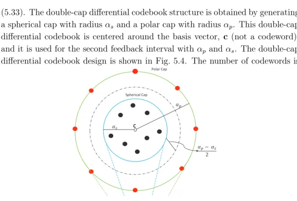
αp Radius of Polar-cap in double-cap differential codebook
αs Radius of Spherical-cap in double-cap differential codebook
χ Estimation error coefficient
dEuclidean Mean Euclidean distance between channel entries over time
κc Scaling parameter for the source constellation
q Ratio between number of transmit antenna and number of users
N Number of states in a trellis
Lc Number of constellation points
C Number of coordinating cells
γc Normalization parameter for RZF precoding matrix in thecth cell
Ec Concatenated quantization error matrix
Tc Concatenated quantized channel matrix
δk,c Expected signal power (without pathloss and shadowing) at the kth user in the cth cell
¯
γc Expected value of normalization parameter for RZF precoding
matrix in thecth cell
ψc Expected interference power (without pathloss and shadowing) at
the user from the cth cell
ψj Expected interference power (without pathloss and shadowing) at
Contents
Acknowledgments i
Acronyms v
Notation and Symbols ix
1 Introduction 1
1.1 Multi-Antenna Downlink Systems . . . 1
1.1.1 Single User Systems . . . 2
1.1.2 Multiuser Systems . . . 2
1.1.3 Multicell Systems . . . 2
1.1.4 Massive Multi-antenna Systems . . . 3
1.2 Limited Feedback Techniques . . . 3
1.3 Research Framework . . . 5 1.3.1 Motivation . . . 5 1.3.2 Contributions . . . 6 1.3.3 List of Publications . . . 8 1.4 Thesis Outline . . . 9 2 Wireless Channels 11 2.1 Wireless Radio Channel . . . 11
2.2 Analytical MIMO Channel Models . . . 14
2.2.1 Rayleigh i.i.d. Channel . . . 14
2.2.2 Rician Channel . . . 14
2.2.3 Spatially Correlated Rayleigh Channel . . . 15
2.2.4 Temporally Correlated Rayleigh Channel . . . 15
2.3 Standardized MIMO Channel Models . . . 16
2.3.1 3GPP Spatial Channel Model . . . 16
2.3.2 WINNER Channel Models . . . 17
2.4 Capacity of MIMO Wireless Channels . . . 21
2.4.1 Perfect CSI at Transmitter . . . 21
2.4.2 No CSI at Transmitter . . . 22
CONTENTS xviii
3 Theoretical Background of Limited Feedback Systems 23
3.1 Limited Feedback Multiple Antenna Systems . . . 23
3.2 SU Systems with Limited Feedback . . . 24
3.2.1 Beamforming . . . 24
3.2.2 Spatial Multiplexing . . . 26
3.3 MU Systems with Limited Feedback . . . 26
3.3.1 ZF Precoding . . . 27 3.3.2 RZF Precoding . . . 27 3.3.3 MF Precoding . . . 28 3.3.4 SLNR Precoding . . . 28 3.4 Codeword Selection . . . 29 3.4.1 SNR Maximization . . . 29
3.4.2 Squared Chordal Distance . . . 30
3.4.3 Capacity Maximization . . . 30
3.4.4 Random Selection . . . 31
3.5 Codebook Quantization Errors . . . 31
3.6 Feedback Update Interval . . . 32
3.7 MIMO Channels and Codebooks . . . 32
3.8 Summary . . . 34
4 MIMO Capacity Analysis 35 4.1 MIMO Capacity Gains . . . 35
4.2 MIMO Capacity Loss Analysis with Limited Feedback . . . 38
4.2.1 System Description . . . 39
4.2.2 Capacity Loss in ZF and MMSE Recivers . . . 41
4.2.3 Capacity Loss in SVD Reciever . . . 43
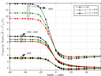
4.2.4 Numerical Results and Discussion . . . 44
4.3 Summary . . . 50
5 MU MISO Systems with Differential Codebooks 51 5.1 Motivation and Related Work . . . 51
5.2 Downlink System Description . . . 53
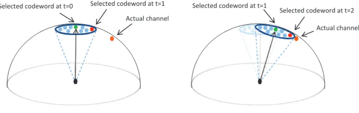
5.3 Spherical-Cap Differential Codebook . . . 54
5.4 Feedback Procedure . . . 55
5.5 Tracking Channel with Spherical-Cap . . . 56
5.6 Rotation Operation on Codebooks . . . 57
5.7 Scaling Operation on Codebooks . . . 57
5.7.1 Adaptive Scaling Technique I . . . 57
5.7.2 Adaptive Scaling Technique II . . . 58
5.8 Double-Cap Differential Codebook . . . 61
5.8.1 Double-Cap Design . . . 62
5.9 Numerical Results and Discussion . . . 65
5.9.1 Comparison of Differential Codebooks . . . 65
5.9.2 Differential Codebooks Versus User Velocity . . . 66
5.9.3 Estimation Errors . . . 67
5.9.4 Performance of Spherical-Cap Differential Codebooks . . 68
5.9.5 Performance of Double-Cap Differential Codebook . . . . 73
5.10 Summary . . . 75
6 MU Massive MISO Systems with TCQ 77 6.1 Motivation and Related Work . . . 77
6.2 System Description . . . 79
6.3 Expected SINR with MF Precoding . . . 79
6.3.1 Perfect CDI . . . 80
6.3.2 RVQ Codebook CDI . . . 81
6.4 Impracticality of RVQ Codebooks For Massive MISO . . . 82
6.5 Limited Feedback with TCQ . . . 83
6.6 Differential TCQ Scheme for Temporally Correlated Channels . 87 6.6.1 Transformed Source Constellation . . . 87
6.6.2 2D Translation and Scaling Techniques . . . 89
6.7 TCQ Scheme for Spatially Correlated Channels . . . 91
6.8 Numerical Results and Discussion . . . 94
6.8.1 Temporally Correlated Channels . . . 95
6.8.2 Spatially Correlated Channels . . . 99
6.8.3 WINNER II Channels . . . 101
6.9 Summary . . . 102
7 Coordinated Multicell MU MISO Systems 103 7.1 Motivation and Related Work . . . 103
7.2 Downlink System Description . . . 105
7.3 Coordinated RZF Precoding . . . 106
7.3.1 Expected SINR with Perfect CDI . . . 107
7.3.2 Expected SINR with RVQ CDI . . . 111
7.4 Adaptive Bit Allocation . . . 115
7.5 Regularization Parameter . . . 117
7.6 Numerical Results and Discussion . . . 118
7.6.1 Coordination Area . . . 118
7.6.2 SINR and Spectral Efficiency . . . 119
7.6.3 Performance of Adaptive Bit Allocation Scheme . . . 122
CONTENTS xx
8 Conclusions and Future Work 127
8.1 Summary . . . 127 8.2 Conclusions . . . 129 8.3 Limitations and Future Work . . . 130 8.3.1 Limitations . . . 130 8.3.2 Future Work . . . 131
Appendices 135
A Proof of Result 1 137
1
Introduction
In this chapter, a brief overview of limited feedback in multiple antenna com-munication systems is presented, followed by the research motivation and major thesis contributions. The outline of the thesis is provided in the last section of this chapter.1.1
Multi-Antenna Downlink Systems
The use of multiple antennas at the transmitter and the receiver have enabled wireless communication systems to improve capacity, quality and reliability [1]. Such systems are known as multiple-input multiple-output (MIMO) systems. The research on MIMO was pioneered by Winters [2], Teletar [3], Alamouti [4] and Foschini and Gans [5]. In MIMO systems, spatial multiplexing and spatial diversity techniques are used to improve the capacity and the reliability, respectively. Spatial multiplexing divides the data into multiple streams and transmits each stream on a different antenna, hence increasing the capacity of the system, the increase being referred to as multiplexing gain [6, 7]. On the other hand, spatial diversity techniques achieve diversity and array gain at the transmitter (transmit diversity) and at the receiver (receive diversity) in turn improving the reliability of the system [1, 8–10]. The trade-off between spatial multiplexing and spatial diversity have been extensively studied in [11–15] (and references within). In addition to the MIMO antenna configuration, there are two other types of antenna configurations: single-input multiple-output (SIMO) and multiple-input single-output (MISO). SIMO has a single transmit antenna and multiple receive antennas, whereas MISO has multiple transmit antennas and a single receive antenna.
1.1. MULTI-ANTENNA DOWNLINK SYSTEMS 2
1.1.1
Single User Systems
In single user (SU) systems, SIMO channels can achieve receive diversity using combining techniques at the receiver, but transmit diversity is not applicable to SIMO channels. Conversely, receive diversity is not applicable to MISO chan-nels but such chanchan-nels can achieve transmit diversity with or without channel knowledge at the transmitter [10]. Transmit beamforming techniques [8, 16–19] with channel state information (CSI) at the transmitter, have been shown to improve the performance of the system in fading channels, by using complex weights at the transmit antennas [20]. The transmit beamforming increases the link signal-to-noise ratio (SNR) and also achieves higher array gains with perfect CSI. However, these gains are somewhat reduced if imperfect CSI is available at the transmitter [17, 21, 22].
1.1.2
Multiuser Systems
Multiple antennas can be used at the transmitter to support multiple users in the same time/frequency resource by assigning one or more antennas per user. Such systems are called multiuser (MU) communication systems. Modern cellular communication systems are multiuser systems, where on downlink the transmitter or base station (BS) uses multiple antennas to serve multiple users. Due to multiple users, MU systems achieve MU diversity [23–25] that provides improvement in the performance as the system resources are only allocated to the users having the best channels and spatial separation.
Precoding is an important component in MU MIMO/MISO systems as it al-lows spatial multiplexing in the downlink [26, 27]. There are various linear and non-linear precoding strategies developed to improve the performance of MU MIMO/MISO systems. Furthermore, CSI at the BS is critical for precoding to achieve user multiplexing. Like SU systems, MU systems also suffer in the ab-sence of perfect CSI at the transmitter. With imperfect CSI, precoding schemes at the BS cannot suppress the interference effectively at the user, caused by other users, therefore reducing the spectral efficiency of the system [27, 28]. In-terference is considered to be one of the limiting factors that reduces the spectral efficiency of MU systems. In a single cell MU communication system, we refer to the interference among the users as inter-user interference (IUI).
1.1.3
Multicell Systems
In addition to IUI, there is another type of interference known as out of cell interference. In cellular communication systems, increasing power of the BS increases the level of interference to other cells, especially in the 4G networks where the frequency reuse factor is one [1]. We refer to out of cell interference
as inter-cell interference (ICI).
Despite the gains provided by the MIMO technology in the single-cell MU system, in practice the users close to the cell-edge are more susceptible to ICI, hence degrading the spectral efficiency of the cell. These systems are also known as multicell systems. In multicell MIMO [29–31], serving and neighboring base stations together contribute in enhancing the performance and reducing ICI. The coordination allows base stations to share the information (such as CSI) related to coordination via a backhaul link. Like MU systems, the quality of CSI at the BS also plays an important role in the performance of multicell MU systems.
1.1.4
Massive Multi-antenna Systems
Massive multi-antenna systems use large numbers of transmit antennas at the base station [32] and a relatively smaller numbers of antenna at the user, re-sulting in a higher spectral efficiency, less inter-user interference and reduced energy consumption [32–34]. The use of large numbers of antennas at the BS also provides highly directional beamforming [1]; the array gain from beamform-ing could improve the link budget. Due to these and several other attractive features, massive MISO is becoming a popular contender for 5G wireless sys-tems. However, there are a number of factors that limit the performance of massive MISO systems, e.g. pilot contamination [34, 35], reduced MU diversity due to channel hardening [36] and high spatial correlation at the BS [37]. An overview of massive MIMO is described in [32] including information theoretic aspects and linear transceivers along with the main design features and practi-cal challenges. The attractive features of massive MIMO systems also apply to massive MISO systems. Like conventional (small-scale) multi-antenna systems, massive multi-antenna systems provide significant performance gains when CSI is available at the transmitter. However, in massive multi-antenna systems, the resources required to obtain CSI at the transmitter increase proportionally to the number of transmit antennas. Time division duplexing (TDD) communica-tion is preferred for massive MIMO systems, but for systems with the imperfect RF chain calibration, limited feedback schemes can be used to equip the trans-mitter with CSI.
1.2
Limited Feedback Techniques
From the above discussion, it is clear that in order for MIMO wireless com-munication systems to provide further improvements in the performance, the transmitter must be able to adapt to changing channel conditions [20]. For this purpose, the transmitter requires some form of CSI. It is not practically possible
1.2. LIMITED FEEDBACK TECHNIQUES 4
to have perfect CSI at the transmitter, in fact CSI at the transmitter incorpo-rates errors such as estimation and quantization, depending on a duplexing method. In TDD transmission, where forward and reverse links usually experi-ence the same fading distribution, CSI can be obtained at the transmitter using channel reciprocity. To accomplish reciprocity in TDD systems, the transmitter and the receiver must have tight RF chain calibration [38–40]. However, in fre-quency division duplexing (FDD) communication, the forward and reverse links are uncorrelated due to different operating frequencies [20]. Therefore, limited feedback techniques are used in FDD MIMO systems to equip the transmitter with CSI; such systems are referred to as closed-loop MIMO. As the focus of this thesis is on limited feedback techniques, we restrict the further discussion to FDD based limited feedback multiple antenna systems.
In limited feedback MIMO systems, the receiver estimates the channel and selects an appropriate codebook entry or codeword and feeds back the index of that codeword to the transmitter. For this purpose, both transmitter and receiver maintains a common codebook. At the receiver, the mismatch between the estimated CSI and the selected codeword gives rise to codebook quantiza-tion error. Due to bandwidth limitaquantiza-tions, a low-rate feedback link is commonly used by the receiver to send the index of the appropriate codeword to the trans-mitter. The number of bits required to send the index of the selected codeword to the transmitter is considered as a feedback overhead and it increases with the number of transmit antennas in MISO systems. Feedback bits are sent to the transmitter using an existing low-rate link for control signals. This link is well protected from errors by using error correcting codes and high trans-mission power. The receiver feeds back CSI frequently so that transmitter can adapt to the changing channel. The performance of limited feedback MIMO systems heavily depend on the codebook design and the quality of the CSI at the transmitter.
Efficient limited feedback schemes aim to minimize the quantization errors by employing effective codebooks and feedback strategy. Limited feedback tech-niques have shown to be effective in providing CSI at the transmitter for both SU and MU systems. The quantized CSI at the transmitter degrades the per-formance compared to the perfect CSI, but the perper-formance with the quantized CSI is still better than the case where no CSI is available at the transmitter.
Limited feedback techniques are part of 4G wireless communications stan-dards such as third generation partnership program (3GPP) long term evolu-tion (LTE) and IEEE 802.16m standards. In order to meet the requirement of the International Telecommunication Union (ITU) for International Mobile Telecommunications advanced (IMT-Advanced) 4G technologies [41], both stan-dards support closed-loop MIMO communication in SU and MU transmissions. The codebooks developed for LTE and IEEE 802.16m standards are different,
targeting different antenna configurations and channel characteristics. Network coordinated and massive MIMO are an integral part of beyond 4G systems, such as 5G cellular systems.
1.3
Research Framework
This section discusses the motivation and the main contributions of the thesis.
1.3.1
Motivation
One of the major factors influencing codebook design in limited feedback sys-tems is the propagation environment. The research on designing a codebook for Rayleigh independent and identically distributed (i.i.d.) channels [22,42,43] has dominated for many years. In practice, MIMO communication channels are spatially/temporally correlated. Codebooks such as the Grassmannian and LTE (designed for Rayleigh i.i.d. channels) do not perform well in correlated chan-nels [44]. The drawback of these codebooks are that they are fixed and cannot adapt to changing channel conditions. In the recent past numerous codebook designs [44–46] have been developed for correlated channels. Depending on a level of spatial and temporal correlation, a codebook can be maneuvered and transformed accordingly after each feedback interval. In this thesis, we refer to such codebooks as differential codebooks.
Recent work on differential codebooks and their importance in next gener-ation of wireless systems motivate us to develop codebooks for MISO systems that exploit spatial and temporal correlation in the channel. By considering the correlation statistics of the channel in a codebook design, the quality of CSI at the transmitter can be improved significantly.
In temporally correlated scenarios, the channel entries do not change abruptly over time. Differential codebooks take advantage of this property and transform the codewords such that they lie close to the previously selected codeword. Hence, enabling the differential codebook to track the slow varying channel. Furthermore, spatial correlation restricts the variation of the channel towards the direction of the eigenvectors of the transmit correlation matrix. Therefore, by taking into account the effects of correlation, differential codebooks with effective adaptive scaling and rotation techniques improve CSI quality at the transmitter and minimize codebook quantization errors [46].
Recently, massive MISO has been widely investigated [47, 48] with limited feedback techniques in FDD based systems. The codebook-based methods are practically infeasible for massive MIMO systems due to the exhaustive search re-quired for selecting the appropriate codeword. This issue of codebook impracti-cality motivates us to design an alternate limited feedback scheme in temporally
1.3. RESEARCH FRAMEWORK 6
correlated channels for massive MISO systems with a lower search complexity. In coordinated multicell systems, adaptive bit allocation methods [49–52] have received enormous attention recently. A typical adaptive bit allocation method divides the total number of feedback bits between the desired and out-of-cell interfering channels by maximizing/minimizing a specific performance/distortion metric. Motivated by existing adaptive bit allocation methods using different precoding schemes, we investigate an adaptive bit allocation scheme for the coordinated regularized zero-forcing (RZF) precoding.
1.3.2
Contributions
In order to make practical and productive use of MIMO technology, limited feedback schemes with effective codebook designs are essential to minimize CSI quantization errors. In this thesis, different aspects of limited feedback schemes are examined. Throughout the thesis multi-antenna downlink systems are con-sidered.
We begin by investigating capacity gains of MIMO systems over single-input single-output (SISO) systems with perfect CSI and no CSI at the transmitter. With imperfect CSI, we analyze the capacity loss due to codebook quantiza-tion errors using well-known codebooks for SU systems with three different MIMO receivers. After considering SU MIMO capacity loss analysis, the focus of the research shifts towards the design of differential codebooks for MU MISO systems in temporally/spatially correlated channels. We investigate various dif-ferential codebook designs, that quantize channel direction information (CDI), by exploiting temporal/spatial correlation in the channel and transforming the codebook after each feedback interval. We also consider massive MU MISO sys-tems with limited feedback to acquire CDI at the transmitter, where we design an effective limited feedback strategy that reduces the search complexity while quantizing temporally correlated channels at the receiver. Finally, we study limited feedback in multicell MU MISO systems for Rayleigh i.i.d. channels and develop a coordinated regularized zero-forcing (RZF) precoding scheme for conventional (small-scale) MU MISO systems.
The main contributions of the thesis are listed below:
• MIMO capacity analysis: The contributions of MIMO capacity gain
and MIMO capacity loss analysis for SU systems are:
– Investigation of capacity gains of the MIMO system over the SISO system using various analytical channel models with perfect CSI and no CSI at the transmitter.
– Derivation of capacity loss approximations in terms of codebook quantization errors for SU MIMO systems with multilayer
transmis-sion and using three different MIMO receivers, namely: zero forcing (ZF), minimum mean-squared error (MMSE) and singular value de-composition (SVD).
– Evaluation of the capacity loss using 3GPP LTE and Grassmannian codebooks and three different MIMO channel models: i.i.d. Rayleigh channel, spatially correlated Rayleigh channel and industry standard based WINNER II channel.
• MU MISO systems with differential codebooks: We study two
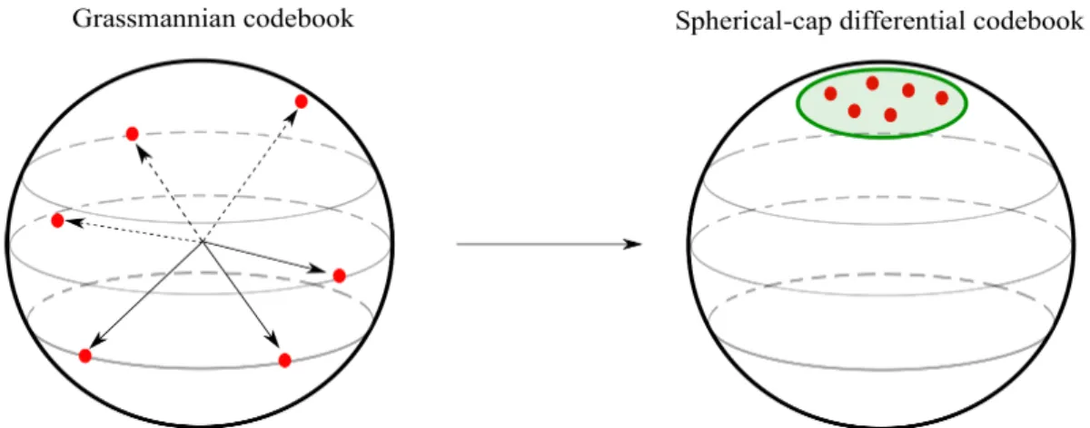
differential codebook structures for single-cell MU MISO systems operat-ing under spatially and temporally correlated channels. The two types of differential codebook designs are based on single-cap (spherical) and double-cap (spherical and polar) structures, where a cap is a spherical region on a sphere with a specific radius. The main contributions of the work are given below:
Spherical cap differential codebook:
– Introduction of an SVD based rotation scheme that effectively rotates the codewords in the codebook to the desired position without errors.
– In order to successfully track the slow varying channel, two adaptive scaling techniques are developed: Adaptive Scaling Technique I and Adaptive Scaling Technique II.
Double cap differential codebook:
– Construction of combined spherical cap and polar cap based differ-ential codebook.
– Development of the blind adaptive scaling technique that leverage the information inherent in a two cap structure to enable scaling up and scaling down of the cap radii
• MU massive MISO systems with differential trellis coded
quan-tization (TCQ): We investigate MU massive MISO systems with limited
feedback in temporally correlated channels. The main contributions are:
– Development of an efficient differential TCQ method that quantizes temporally correlated channels at the receiver with a lower search complexity than that of conventional codebook schemes.
– Transformation of the TCQ source constellation by using 2D trans-lation and scaling techniques.
– Derivation of a scaling factor for the TCQ source constellation as a function of the number of BS antennas and the temporal correlation.
1.3. RESEARCH FRAMEWORK 8
– Development of a TCQ based limited feedback scheme for spatially correlated massive MISO channels using uniform linear array (ULA) and uniform rectangular array (URA) antenna topologies.
• Coordinated multicell MU MISO systems: We study coordinated
multicell MU MISO systems for i.i.d. Rayleigh channels with limited feedback. The contributions of this work are summarized as follows:
– Development of a coordinated RZF precoding strategy where the serving BS of the cell shares out-of-cell interfering channels with the respective interfering base stations to minimize interference in the network.
– Derivation of expected signal-to-interference-plus-noise ratio (SINR) approximations for coordinated RZF scheme with both perfect CDI and limited feedback based quantized random vector quantization (RVQ) CDI.
– Development of an adaptive feedback bit allocation strategy that minimizes the interference in the network.
1.3.3
List of Publications
The content of this thesis has been partially published, accepted or submitted for publication in the papers listed below.
1. M. Zhang, P. J. Smith, M. Shafi, P. A. Dmochowski, J. Mirza, “MIMO Capacity Gain Analysis for General Channel Models”, in Proc. IEEE
In-ternational Conference on Communications (ICC), pp. 4846-4851, 2012.
2. J. Mirza, P. A. Dmochowski, P. J. Smith, M. Shafi, “Capacity Loss for Multilayer Codebook Precoding in MIMO Systems”, in Proc. 23rd IEEE International Symposium on Personal, Indoor and Mobile Radio
Commu-nications (PIMRC), pp. 1890-1895, 2012.
3. J. Mirza, P. A. Dmochowski, P. J. Smith, M. Shafi, “Limited feedback mul-tiuser MISO systems with differential codebooks in correlated channels”,
in Proc. IEEE International Conference on Communications (ICC), pp.
5386-5391, 2013.
4. J. Mirza, P. A. Dmochowski, P. J. Smith, M. Shafi, “A differential code-book with adaptive scaling for limited feedback MU MISO systems”,IEEE
5. J. Mirza, P. J. Smith, M. Shafi, P. A. Dmochowski, A. Firag, A. Pap-athanassiou, “Double-Cap Differential Codebook Structure for MU MISO Systems in Correlated Channels”,IEEE Wireless Communications Letters, pp. 441-444, 2014.
6. J. Mirza, M. Shafi, P. J. Smith, P. A. Dmochowski, “Limited Feedback Massive MISO Systems with Trellis Coded Quantization for Correlated Channels”,accepted in IEEE Transactions on Vehicular Technology, 2015.
7. J. Mirza, P. J. Smith, P. A. Dmochowski, M. Shafi, “Coordinated Reg-ularized Zero-Forcing Precoding for Multicell MISO Systems with Lim-ited Feedback”, submitted to IEEE Transactions on Vehicular Technology, 2015.
1.4
Thesis Outline
The rest of the dissertation is organized as follows:
Chapter 2 introduces the theoretical background of MIMO channel models that are used in this thesis. The MIMO channel models are classified into two categories: analytical and standardized MIMO channel models.
Chapter 3 provides an overview of basic concepts and background theory in limited feedback MIMO systems.
Chapter 4 gives the capacity loss analysis of the SU MIMO limited feedback system using LTE and Grassmannian codebooks. This chapter begins with a brief description of MIMO capacity gains without limited feedback. Later, in the capacity loss analysis, single stream and two stream MIMO transmission modes are considered. The capacity loss expressions are also derived using different MIMO receivers, followed by numerical results and discussion.
Chapter 5 investigates differential codebook designs for spatially/temporally correlated MU MISO channels. This chapter is divided into two categories: single spherical-cap and double-cap differential codebooks. Various adaptive scaling techniques are discussed for both differential codebook designs. An SVD based codebook rotation method is discussed. Simulation results are also presented for single spherical-cap and double-cap differential codebooks.
Chapter 6 focuses on massive MU MISO systems with limited feedback. As motivation, the impracticality of RVQ codebooks is discussed. Later, a dif-ferential TCQ method is presented to quantize the channel (at the user) and reconstruct the channel (at the BS) in temporally correlated channels. The 2D translation and scaling techniques for differential TCQ are also presented. A scaling parameter that is a function of the number of transmit antennas and temporal correlation is derived for the source constellation. A TCQ based
lim-1.4. THESIS OUTLINE 10
ited feedback scheme for spatially correlated channels is investigated, followed by numerical results and discussion.
Chapter 7 studies coordinated multicell MU MISO systems in Rayleigh i.i.d. fading channels. First, coordinated RZF scheme is described, followed by the expected SINR analysis for both perfect CDI and RVQ based imperfect CDI. An adaptive bit allocation strategy is also presented in this chapter. Finally, simulation results are presented for the coordinated RZF precoding scheme.
Chapter 8 draws conclusions from the contributions of the thesis and suggests future research directions.
2
Wireless Channels
An overview of MIMO channels is presented in this chapter. First, some key concepts of wireless channels are discussed, followed by a detailed explanation of analytical and standardized MIMO channel models used in this thesis. We also discuss the capacity of MIMO wireless channels assuming that perfect CSI is available at the receiver.2.1
Wireless Radio Channel
It is important to understand the characteristics of wireless communication channels, as they generally dictate the performance of wireless systems.
In a typical wireless communication system, the variation in the power of the received signal with respect to distance is generally due to path loss and shadowing [23]. These variations usually occur at large distances, and are thus also referred to as large-scale propagation effects. On the other hand, multipath where a signal reaches the receiver from two or more paths (and adds up con-structively or decon-structively) is termed small-scale propagation effects [23]. The effects of large-scale and small-scale fading are illustrated in Fig. 2.1, where Pt
is the transmit signal power, Pr is the receive signal power and the distance
between the transmitter and receiver is denoted by d.
The well-known free-space path loss model is commonly used when there is no obstruction in the path of the signal [23]. Also, there are numerous ray-tracing propagation models developed when the geometry of the region is known and there are few multipath components [23]. In addition to free space path loss and ray-tracing models, there are some empirical path loss models that are developed to estimate the path loss in the typical wireless communication
2.1. WIRELESS RADIO CHANNEL 12 log10(d) Pr /P t [d B ] Path loss
Path loss, shadowing and multipath
Path loss and shadowing
Figure 2.1: Effects of path loss, shadowing and multipath on Pr/Pt (dB) ratio
with log distance [23].
environments such as urban macro (UMa), urban micro (UMi), outdoor-to-indoor (O2I) and a few others. Empirical path loss models are developed by Okumara, Hata, COST 231, SUI, LTE and many other studies.
In this thesis, we consider a combined path loss and shadowing model for evaluating the performance of cellular systems. The received signal power with the combined path loss and shadowing model is written in linear scale as [24]
Pr =P0 Rc d a Φ, (2.1)
where P0 is the received power at the radius Rc without shadowing, and a is a
path loss exponent. The shadowing is modeled as a log-normal random variable, given by Φ = 10(ησSF/10), where σ
SF is the shadowing standard deviation in dB andηis a zero mean Gaussian random variable with unit variance. The distance
d represents the distance of the receiver from the transmitter.
For any SISO link, the channel impulse response (CIR) of the time-varying fading multipath channel is given by [24]
h(τ, t) = X
i
αi(t)δ(τ −τi(t)), (2.2)
where t and τ denote time and delay, respectively. αi is the overall attenuation
and τi is the propagation delay at time t for the pathi, from the transmitter to
the receiver.
Now, we briefly discuss the concept of time-frequency coherence in a wireless communication channel. The coherence time, Tc, of the channel is inversely
proportional to the Doppler spread, Ds, such that, Tc = 1/4Ds [24]. If the
maximum difference between the Doppler shifts of paths i and j, such that
Ds := max
i,j fc|τi(t)−τj(t)|. (2.3)
When the coherence time, Tc is smaller than the delay requirement of the
ap-plication, Treq, the channel is considered to be a fast fading channel and a slow fading channel if Tc is larger than Treq [24].
Another key time-frequency coherence parameter of the wireless communica-tion channel is the coherence bandwidth, Bc, defined as Bc = 1/2Td [24], where Td is the delay spread given by
Td:= max
i,j |τi(t)−τj(t)|. (2.4)
A channel is considered to be flat fading when Bc is much greater than the
bandwidth of the signal, Bs, i.e.,Bc ≫Bs and frequency selective fading when Bc ≪Bs. Table 2.1, shows the types of wireless channels. In wideband channels,
Table 2.1: Types of wireless channels [24].
Type Definition
Fast fading Tc ≪Treq Slow fading Tc ≫Treq Flat fading Bs≪Bc
Frequency selective fading Bs≫Bc
multipath components are resolvable as the delay spread of the channel is greater than the inverse of the bandwidth of the signal, i.e.,Td≫ Bs−1. On the contrary,
in narrowband channels multipath components are non-resolvable asTd≪B−s1.
Therefore, in narrowband channels, we have hnr,nt(t, τ)≈ hnr,nt(t).
The discussion so far only considered a SISO link. For MIMO channels withnttransmit andnrreceive antennas, the wideband MIMO channel matrix,
H(t, τ)of size nr×nt is written as H(t, τ) = h1,1(t, τ) h1,2(t, τ) · · · h1,nt(t, τ) h2,1(t, τ) h2,2(t, τ) · · · h2,nt(t, τ) ... ... . .. ... hnr,1(t, τ) hnr,2(t, τ) · · · hnr,nt(t, τ) , (2.5)
wherehnr,nt(t, τ)is a CIR between then th
t transmit and thenthr receive antenna.
Most of the channels used in this thesis are narrowband channels. However, when evaluating capacity loss for MIMO orthogonal frequency-division multi-plexing (OFDM) channels in Chapter 3, we use wideband channels. In the next two sections, we discuss analytical and standardized MIMO channel models.
2.2. ANALYTICAL MIMO CHANNEL MODELS 14
2.2
Analytical MIMO Channel Models
Analytical channel models, also referred as stochastic channel models give the statistical representation of the channel. Although, they do not fully match real-world channels, they are widely used to evaluate the performance of MIMO systems. In this section, we discuss four kinds of analytical MIMO channel models, namely, Rayleigh i.i.d., Rician, spatially correlated and temporally cor-related channel models.
2.2.1
Rayleigh i.i.d. Channel
The Rayleigh i.i.d. Channel is the simplest statistical MIMO channel model for rich scattering and non-line-of-sight (NLoS) environments [3]. In Rayleigh i.i.d. MIMO channels, each link is assumed independent and complex random variable with Rayleigh distributed amplitude and uniformly distributed phase [1]. This model is practically suitable when the spacing between the antenna elements is sufficiently large and angular spreads are large (rich scattering) at the transmitter and the receiver. The entries of i.i.d. Rayleigh MIMO channel matrix, H, are independent and distributed according to CN(0,1). Without considering path loss and shadowing, the i.i.d. Rayleigh MIMO channels follow
EkHk2
F
=ntnr. (2.6)
In this thesis, we extensively use MISO channels where the receiver has only one antenna. In such cases, Rayleigh i.i.d. MISO channel, h, is a vector of size 1×nt, whereE[khk22] =nt.
2.2.2
Rician Channel
Rician channel models are used in the scenarios where there exists a strong line-of-sight (LoS) path between the transmitter and the receiver. The LoS path is independent of fading [1], therefore it is not modeled as a zero-mean random variable [23]. The Rician channel consists of both LoS and NLoS components and it is modeled as HRician = s Kf 1 +Kf HLoS+ s 1 1 +Kf H (2.7)
where HLoS is the matrix containing LoS components. The entry (i, j) of the
HLoScan be expressed as ejθi,j, whereθi,j is the uniform phase. His the Rayleigh
i.i.d. channel and Kf is the so-called K factor. The K factor is defined as the
When Kf = 0, we have the Rayleigh i.i.d. channel in (2.7) and for Kf =∞we
get only the LoS component. The distribution of the magnitude of the channel entries in (2.7) is Rician.
2.2.3
Spatially Correlated Rayleigh Channel
For spatially correlated Rayleigh MIMO channels, we rely on the separable Kronecker model [53, 54], where correlation matrices are used to express the spatially correlated Rayleigh MIMO channel as
ˆ
H=R1r/2HR1t/2, (2.8) whereRrandRt are the receive and transmit correlation matrices, respectively.
H is the i.i.d. Rayleigh MIMO channel. This model is useful when the spacing between the antenna elements is small either at the transmitter, the receiver, or both. The underlaying channel in (2.8) is the i.i.d. Rayleigh channel which assumes independent and rich scattering at both ends, therefore making it pos-sible to separate the transmit and receive correlations. In this thesis, the entries of correlation matrices Rt and Rr follow an exponential model [55], given by
rtij =ztdij (2.9)
and
rijr =zdrij, (2.10) respectively, where dij is the distance between the antenna i and j. z
t and zr are the transmit and receive correlation coefficients. The magnitude of zt and
zr varies from 0 to 1, where 0 represents no spatial correlation and 1 means full correlation, i.e., the same fading on both links. In a MISO channel, (2.8) simplifies to
ˆ
h=hR1t/2. (2.11)
where h is the i.i.d. Rayleigh MISO channel. The exponential correlation model has shown to be reasonable for the equally-spaced linear antenna arrays, but it may not be a valid model for some real-world scenarios. However, the exponential model is a simple model which is helpful in studying the effect of correlation on the MIMO capacity and also provides some useful insights [55].
2.2.4
Temporally Correlated Rayleigh Channel
Most of the work done in this thesis considers temporally correlated channels. When the receiver is moving slowly, its channel entries vary slowly over time. A first-order Gauss-Markov (FOGM) filter, is used to model the temporally
2.3. STANDARDIZED MIMO CHANNEL MODELS 16
correlated MIMO channel at time t as [24, 56]
˜
H[t] =ǫH˜[t−1] +√1−ǫ2Y[t], (2.12)
where ǫis a temporal correlation coefficient that follows Jakes’ model (which is an isotropic scattering leading to Bessel function), such that, ǫ = J0(2πfdTs),
where J0 is a Bessel function of zeroth order, fd is the maximum Doppler
fre-quency andTs is the channel sample time. Y[t]is an innovation process with its
entries distributed according to CN(0,1). For fast moving receivers, ǫ is close to or equal to zero and for slow moving receivers the ǫ value is close to one.
For temporally correlated MISO channels, we have
˜
h[t] =ǫh˜[t−1] +√1−ǫ2y[t]. (2.13)
A combined spatially and temporally correlated MISO channel can also be mod-eled as [1, 46]
¯
h[t] =ǫh¯[t−1] +√1−ǫ2y[t]R1/2
t . (2.14)
In this thesis, we have extensively used analytical MIMO/MISO channel models, however we also used standardized MIMO channel models in order to evaluate the performance of the developed methods and schemes under more realistic propagation environments.
2.3
Standardized MIMO Channel Models
Several standards for MIMO channels are developed by various international organizations including 3GPP and IMT-Advanced [57]. These standards are sometimes extended in order to improve spatial channel modeling by support-ing more MIMO technologies and propagation scenarios. Mostly, the standards follow geometry-based stochastic channel modeling approaches, where statistics of the key channel parameters are estimated using real-time channel measure-ments. In this section, two standards are discussed, namely, 3GPP spatial channel model (SCM) and Wireless World Initiative New Radio (WINNER) channel models.
2.3.1
3GPP Spatial Channel Model
3GPP SCM [58] has been designed for outdoor scenarios with system bandwidth of 5 MHz, operating at around 2 GHz carrier frequency. The outdoor scenarios supported by the SCM model are UMa (only NLoS), UMi (both LoS and NLoS) and suburban macro (SMa) (only NLoS). The statistics of channel parameters are obtained from real-world channel measurements. Polarized antennas are also
included in 3GPP SCM. Due to lack of scenarios considered and few LoS Rician K-factor results, 3GPP SCM model has been extended by SCME (extended-SCM). SCME supports bandwidths up to 100 MHz and carrier frequency of 5 GHz. This model aids both LoS and NLoS environments in UMa, UMi and SMa scenarios. Both SCM and SCME lack some features such as indoor scenarios, LoS measurements, elevation angles and time evolution.
2.3.2
WINNER Channel Models
WINNER channel models target beyond 3G wireless systems with higher band-widths and operating frequencies. This model includes both outdoor and indoor scenarios. Apart from additional scenarios, it also includes more results on LoS Rician K-factor. The WINNER project introduced WINNER I channel models initially and those were later extended by WINNER II channel models. Fi-nally, WINNER+ channel models have been developed which are evolved from WINNER I and WINNER II channel models.
WINNER I [59] supports 7 outdoor/indoor scenarios and introduce two types of models: geometric-based stochastic model and reduced variability (cluster delay line) model. The geometric-based stochastic model allows the genera-tion of a double direcgenera-tional propagagenera-tion channel which is antenna independent and supports multi-links. In the WINNER I project, measurements are per-formed at 2 GHz and 5 GHz carrier frequencies with 100 MHz bandwidth. The channel parameters investigated are power delay profile, path loss, shadowing, delay spreads, angle spreads and cross-polarization ratio (XPR). The model also provides correlation between large-scale parameters WINNER II channel models [60] for link and system level simulations are evolved from WINNER I. It supports 11 outdoor and indoor scenarios. Apart from new scenarios, this model also features steady time and space evolution. The model is scalable from a single-cell SU/MU SISO/MIMO to SU/MU multicell MIMO. Both fixed and moving relay stations are supported by WINNER II channel models. Some additional features include modeling of elevation rays and moving scatterers. WINNER II channels have been the starting point for the IMT-Advanced based channel model (M.2135) recommended by ITU-R.
WINNER+ channel models [61] are developed to support IMT-Advanced technologies like 3GPP LTE-Advanced. WINNER+ upgrades 2D channel mod-els to 3D channel modmod-els by specifying elevation angles, and large-scale and small-scale parameters for the elevation domain. For the elevation domain, large-scale and small-scale parameters are assumed to have normal and Laplace distributions, respectively. This model is applicable to wireless systems operat-ing in 450 MHz to 6 GHz frequency range.
2.3. STANDARDIZED MIMO CHANNEL MODELS 18
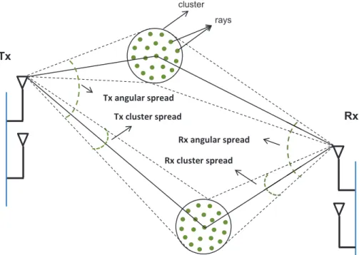
II channel models [60]. The single link between the transmitter and the receiver in the WINNER II channel model is shown in Fig. 2.2.
The single link model consists of a finite number of clusters and each cluster has a fixed number of rays. For example, the number of clusters for UMa scenario is 20, whereas, for rural macro (RMa) propagation scenario the number of clusters is 10. For both the scenarios, the number of rays in each cluster is 30. Each ray has its own angle of departure (AoD) and angle of arrival (AoA). All the
cluster rays Tx angular spread Tx cluster spread Rx angular spread Rx cluster spread Tx Rx
Figure 2.2: The single link between the transmitter and the receiver in the WINNER II channel model.
Table 2.2: WINNER II MIMO channel model parameters
Parameters UMa RMa 02I-UMa
Delay,τ, spreadlog10(s)
µ -6.63 -7.60 -6.62
σ 0.32 0.48 0.32
Azimuth AoD,φ, spreadlog10(degree)
µ 0.93 0.96 1.76
σ 0.22 0.45 0.16
Azimuth AoA,ϕ, spreadlog10(degree)
µ 1.72 1.52 1.25
σ 0.14 0.27 0.42
Cross-polarization ratio (XPR) (dB) µ 7 7 9
σ 3 4 11
Number of clusters 20 10 12
Delay distribution EXP
clusters in the link have different power and delay values associated with them. The WINNER II channel model incorporates various antenna configurations such as co-polarized, dual polarized and group polarized. Benefit of using the WINNER II channel model is that it can be used to generate both narrowband and wideband communication channels.
The parameters of WINNER II channels for UMa, RMa, and O2I-UMa scenarios under the NLoS propagation are summarized in Table 2.2.
In this thesis, MATLAB simulation of the WINNER II channel model in [62] are used to generate the MIMO channel.
Narrowband WINNER II channel
The narrowband WINNER II channel coefficient between theithreceive antenna and thekth transmit antenna, for the nth cluster is given by
h(i, k, n, t) =pPn Mr X m=1 " Fi,V(ϕn,m) Fi,H(ϕn,m) #T " ejΘV V n,m √̟ n,mejΘ V H n,m √̟ n,mejΘ HV n,m ejΘHHn,m # × " Fk,V(φn,m) Fk,H(φn,m) # exp (jdk2πλ−01sin (φn,m))
×exp (jdi2πλ−01sin (ϕn,m)) exp (j2πvn,mt), (2.15)
where:
• Mr is the total number of rays in the cluster.
• Pn is the power of thenth cluster.
• Fi,V and Fi,H are receive antenna field patterns for the vertical and
hori-zontal polarizations respectively.
• Fk,V and Fk,H are transmit antenna field patterns for the vertical and
horizontal polarizations respectively.
• ΘV V
n,m,ΘV Hn,m,ΘHVn,mandΘHHn,mare initial random phases uniformly distributed
from−π toπ, for the nth cluster and the mth ray.
• λ0 is the wavelength of the carrier frequency.
• φn,m is AoD for the ray coming from the nth cluster and mth ray.
• ϕn,m is AoA for the ray coming from thenth cluster and mth ray.
• dk and di are the transmit antenna and the receive antenna spacing,
2.3. STANDARDIZED MIMO CHANNEL MODELS 20
• vn,m is the velocity component corresponding to the mth ray in the nth
cluster.
• ̟n,mis the cross polarization power ratio (XPR) corresponding to themth
ray in the nth cluster.
In order to generate a narrowband channel, the channel coefficients from different clusters are summed together. The resulting narrowband channel co-efficient for any given time t is
h(i, k, t) =
Ns
X
n=1
h(i, k, n, t). (2.16)
where Ns is the total number of clusters. In (2.15), both spatial correlation
and temporal correlation are present. The spatial correlation is induced by the transmit antenna spacing, dk, and the receive antenna spacing, di, the smaller
the spacings, the higher the spatial correlation in the channel and vice versa. On the other hand, the velocity component, vn,m, controls the amount of temporal
correlation in the channel, where higher the velocity, the lower the temporal correlation in the channel, and vice versa.
Wideband WINNER II channel
Unlike narrowband channels, the wideband channels consider the time dispersive nature of the communication channel. Therefore, the delay associated with each ray is required in order to model a wideband channel. The wideband channel coefficient, between theithreceive antenna and thekth transmit antenna, at any particular time t with path delay τ is given by
h(i, k, t, τ) =
Ns
X
n=1
h(i, k, n, t, τ), (2.17)
where the wideband channel for the nth cluster is given by
h(i, k, n, t, τ) =pPn Mr X m=1 " Fi,V(ϕn,m) Fi,H(ϕn,m) #T " ejΘV Vn,m √̟ n,mejΘ V H n,m √̟ n,mejΘ HV n,m ejΘHHn,m # × " Fk,V(φn,m) Fk,H(φn,m) # exp (jdk2πλ−01sin (φn,m))
×exp (jdi2πλ−01sin (ϕn,m)) exp (j2πvn,mt)δ(τ −τn,m). (2.18)
In Chapter 4, we generate a wideband MIMO channel for an OFDM system using (2.17) assuming all the rays within the cluster have same delay. The
channel frequency response is required in wideband MIMO channels, in order to solve for the cluster delay values.
In this thesis, two basic antenna configurations, namely: co-polarized and dual polarized are considered. We consider co-polarized antennas where dipole antennas are mounted vertically (single polarization). For the dual polarized antenna case, we consider a pair of dipole antennas which are vertical/horizontal arrays having +/−45 degree slant orientation.
2.4
Capacity of MIMO Wireless Channels
In this section, we discuss the capacity of SU MIMO channels. We assume that perfect CSI is available at the receiver and discuss two cases: perfect CSI and no CSI at the transmitter.
2.4.1
Perfect CSI at Transmitter
The capacity of the MIMO channel when both transmitter and receiver have perfect CSI is given by [3, 5]
¯
C = max
Q:tr(Q)=ρlog2det I+HQH
H, (2.19)
where Q is the input covariance matrix. ρ is the average SNR defined as ρ =
Pt/σ2 wherePt is the total transmit power andσ2 is the noise power. In [24], it
is shown that the MIMO channel can be decomposed into min(nt, nr) parallel
independent SISO channels by taking the SVD of the channel matrix H. For the MIMO channel, the SVD of H is H = UDVH, where U ∈ Cnr×nr and
V ∈Cnt×nt are unitary matrices andDis a diagonal matrix containing them = min(nr, nt) singular values of H. Waterfilling is used to allocate the transmit
power to these parallel SISO channels. The capacity of the MIMO channel with waterfilling is written as [3] ˜ CM = m X i=1 log2 1 + 1 σ2 λiµ−σ 2+ , (2.20)
where µis the waterfill level and λi is theith eigenvalue of the matrixΥ, given
by Υ= ( HHH n r ≤nt HHH nt ≤nr . (2.21)
2.5. SUMMARY 22
2.4.2
No CSI at Transmitter
When the channel is unknown to the transmitter, but channel statistics are known at the transmitter then it is shown in [3] that the ergodic capacity is maximized by having Q= (ρ/nt)I (i.e., equal power allocation to all the
trans-mit antennas). Thus, the capacity of the MIMO channel can be expressed as
CM= log2det I+ ρ nt Υ . (2.22)
On the other hand, the SISO capacity is given as
CS = log2 1 +ρ|h| 2
, (2.23)
where h is the SISO channel coefficient.
2.5
Summary
In this chapter we have presented an overview of analytical and standardized MIMO channel models. In analytical MIMO channel models four commonly used channels are discussed: Rayleigh i.i.d., Rician, spatially correlated and temporally correlated channels. In addition to analytical models, MIMO stan-dardized channel models are also discussed. In this thesis, both analytical and standardized channel models are used. We have also discussed the capacity of MIMO channels assuming perfect CSI is available at the receiver.
3
Theoretical Background of Limited
Feedback Systems
In this chapter, we provide a general overview of limited feedback systems. We briefly discuss beamforming and spatial multiplexing for SU systems and linear precoding for MU systems with limited feedback. We explain basic concepts of limited feedback systems, such as codeword selection, quantization errors and feedback interval. We also examine the distribution of the dominant right singular vector for various channels.3.1
Limited Feedback Multiple Antenna Systems
Research in MIMO systems has shown that CSI at the transmitter improves the performance in terms of capacity and reliability. However, providing perfect CSI to the transmitter is not possible under a low-rate feedback control channel from the receiver to the transmitter. Researchers have designed various techniques that try to efficiently utilize this low-rate feedback link, so that the quantized channel information delivered to the transmitter achieves the desired perfor-mance with a minimum loss relative to the case where perfect CSI is available. The codebook based limited feedback approach is considered to be a successful technique for this purpose [20]. The block diagram of the basic limited feedback MIMO system is shown in Fig. 3.1.In limited feedback schemes, the main idea is that the receiver estimates the channel and quantizes it using a codebook. In this thesis, for SU MIMO systems, we quantize the dominant right singular vectors of the channel at the receiver, whereas, in MU systems, we quantize CDI for each user. Generally, the channel
3.2. SU SYSTEMS WITH LIMITED FEEDBACK 24 Transmitter Receiver Feedback Link Transmitter Codebook Receiver Codebook
Figure 3.1: The block diagram of a limited feedback MIMO system.
quantization is realized by selecting a codeword that maximizes/minimizes a specific performance/distortion function (SNR, squared chordal distance etc.). Suppose there are Nc codewords in the codebook, the receiver selects an
ap-propriate codeword and feeds back the index of the selected codeword to the transmitter via a low-rate feedback link, using B = log2(Nc)bits. Due to
band-width limitations, the number of feedback bits required to feedback the index of the selected codeword is considered as feedback overhead. The feedback link is generally assumed to be a lossless with zero delay, for study purposes. There are many studies [63–66] that investigate codebook quantization with delayed and lossy feedback links. At the transmitter, the same codebook is already available and it selects the codebook entry corresponding to the sent index. In SU scenarios, the transmitter may use this codeword directly as a beamforming vector, however, in MU transmission further processing may be required at the BS to eliminate or suppress the interference coming from other users. The main focus of the research in limited feedback systems is to use the minimum number of bits and obtain maximum quality of CSI at the transmitter.
3.2
SU Systems with Limited Feedback
In this section, we briefly discuss limited feedback in SU systems. Based on the transmission strategy, SU multiple antenna systems can be categorized into two parts: beamforming and spatial multiplexing.
3.2.1
Beamforming
Beamforming achieves array and diversity gains by transmitting the same sym-bol weighted by a complex number from each transmit antenna. The weights at all the antennas can be collected into a beamforming vector, denoted by w.
In the case of MIMO, the signals at multiple receive antennas are combined by a weighted summation to obtain the resulting symbol.
It is shown in [8] that the received SNR is maximized when weights at the transmitter and receiver are vdom and uHdom, respectively, where vdom and udom are the right and left singular vectors associated with the dominant singular value of the channel, H. This scheme is also known as dominant eigenmode transmission.
In the case of the MISO system, matched-filter (MF) beamforming [67] is used to maximize the receive SNR, where the beamforming vector is given by
w=hH/khk. This technique is also known as conventional beamforming. The above discussion is for the case when perfect CSI is available at the transmitter. For limited feedback MIMO/MISO systems, the performance de-grades when using quantized beamforming vectors from the codebook. The amount of capacity loss and SNR loss with quantized beamforming is investi-gated in [42, 68, 69]. The capacities of the MIMO system and the MISO system with limited feedback beamforming vector denoted by f and q, are given by
CMIMO-BF = log2 1 + ρ ntk Hfk2 (3.1) and CMISO-BF= log2 1 + ρ nt| hq|2 , (3.2) respectively.
There are numerous studies [42, 70–72] that examine the performance of MIMO beamforming with limited feedback techniques. Beamforming techniques in limited feedback MISO systems are also well investigated in [22, 27, 73].
In order to measure the average loss in the array gain due to the quantized beamforming vectors, the distortion function for MIMO systems that is generally used is given by [1] Df =E λmax− kHfk2 , (3.3)
where λmax is the dominant singular value of the channel H, (array gain with perfect CSI). The quantized codebook beamforming vector is denoted f. Simi-larly for the MISO system, the distortion function is given by
Df =E
1− |hq|2, (3.4)
where qis the selected beamforming vector from the codebook. The distortion function for various codebook designs is thoroughly discussed in [1].