in manual drilling
GROUNDWATER & WELLS
for manual drilling
teams on
hydro-geology
for well drilling,
well installation and
well development
INSTRUCTION
HANDBOOK
GROUNDWATER & WELLS
in manual drilling
Instruction handbook for manual drilling teams
on hydro-geology for well drilling,
well installation and well development
Published by the PRACTICA Foundation
Author – Arjen van der Wal
Peer reading – Richard C. Carter
Structural support – Wouter Jan Fellinga , Melanie Stallen
French translation – Julien Labas, Stéphan Abric, Régis Garandeau
Swahili translation – Walter Mgina, Ester Mgina-van Vugt
Illustrations – Franck Nederstigt
Photos – Arjen van der Wal
Layout – Marijke Kreikamp/ 4colour design
First edition – April 2008
Second edition – June 2010
PRACTICA Foundation develops and disseminates low-cost appropriate technology in water and renewable energy in developing countries. We focus on technology that responds to local cultural contexts, can be locally produced and maintained, and supports existing markets.
PRACTICA foundation Oosteind 47 - NL-3356 AB Papendrecht - The Netherlands
(t) +31(0)786150125 [email protected] www.practicafoundation.nl
may be copied to meet local needs, without permission
from the author or publisher, provided the parts are
distributed free, not for profi t and reference to the source is made. The author would appreciate receiving notice and a copy of any materials in which original text or pictures have been used. For any reproduction with commercial ends, written permission must be obtained in advance from the PRACTICA Foundation.
This instruction manual is available in English and in French and Swahili and has been developed for use in technical training courses organised for the intended users. In case you want to organize such training, you may contact the PRACTICA Foundation for further information and support.
The fi rst edition of this publication was made possible by a fi nancial contribution from the Technical Training Programme of the ETC Foundation in the Netherlands and
the United Nations Children’s Fund - UNICEF - offi ce in
Chad. An updated version of this publication (the second edition) was made possible by a fi nancial contribution from the United States Agency for International Development (USAID) as part of the West Africa Water Initiative (WAWI).
The Technical Training Program (TTP) of the ETC Foundation contributed with structural support in the educational aspects of this manual.
While every care has been taken to ensure accuracy of the information given in this manual, neither the publisher(s) nor the author(s) can be held responsible for any damage resulting from the application of the described methods. Any liability in this respect is excluded.
Note to those considering translation or modifi cation; before beginning any translation or modifi cation and in order to
avoid duplication of eff orts and unintended mistakes, please contact the PRACTICA Foundation. This document or parts of this document may not be copied or published under a new name or author without permission from PRACTICA Foundation.
(UNICEF), PRACTICA Foundation and Enterprise Works/Vita have developed a toolkit for African countries wishing to embark on the professionalization of manual drilling. This toolkit includes Technical Notes, Technical Manuals including this publication, Advocacy Materials, Mapping of suitable areas for manual drilling, Case Studies, and Implementation and Training Manuals. This initiative builds the capacity of the local private sector in order to respond to the ever increasing demand for safe water in rural areas.
Context
Over the years much literature on geology, hydrogeology and hygienic aspects has been written and in a lot of countries this information is used by policy makers, project managers, engineers and technicians to construct machine-drilled wells in their countries.
Machine-drilled wells are often very expensive and not aff ordable by large parts of the population in developing countries. Another option is to drill ‘shallow’ water wells (up to about 35 meter depth) by hand, so reducing the price of a well by a factor 4 -10 compared to a machine-drilled borehole. This cost reduction not only enables NGOs and Governments to construct more water wells, but also ‘opens the door’ to villagers, farmers, schools and small communities to have a well constructed independently through the private sector.
Although most of the existing manual drilling enterprises are technically able to drill boreholes, mistakes are easily made during the construction and development of the wells. Furthermore good well construction alone does not
ensure good water quality and sustained yield from the well over many years. In order to achieve that, know-how on geology and groundwater is important.
However, many technical workers of manual drilling enterprises may have limited education. Much of the available literature on geology, hydrogeology and hygiene cannot easily be understood without an advanced education.
Technical workers are used to learn through experience and repetition. Of course training could be given to these workers but classroom training alone is known to
be insuffi cient for drilling teams. They need to relate
theoretical information to the real practical problems which occur regularly while working on drilling sites. This book therefore only deals with those essential subjects which are relevant to manual drilling and well installation in practice, in simple and understandable language.*
*Note
Technical terms and the way in which subjects are explained are based on the average expected educational level of the intended users. Sometimes, the use of complicated geological and technical terms has been avoided to create better understanding. Some words (for example ‘soil’ or ‘gravel pack’) have been used because they are known by the intended users, although these words are not always the terms that are used by geologists. Please keep in mind that the objective of the handbook is to create better understanding of well drilling in practice, aimed at technical workers of manual drilling teams who may have a limited educational background.
READERSHIP
This handbook can be used as a guide during training sessions for well drillers, local trainers and quality controllers. It also serves as a reference for drilling supervisors, NGOs, development agencies, manual drilling teams and enterprises during the entire drilling process. The handbook consists of three sections that can be read together, or used and printed separately for the various target groups.
AVAILABLE MANUALS IN THIS SERIES:
Technical training handbooks on affordable manual well drilling.
These practical handbooks create awareness of manual drilling for aff ordable water supply and a roadmap for implementation of manual drilling programs. The manuals provide an extensive and detailed guide for trainers and drilling teams in the use of various drilling techniques for making aff ordable boreholes. The techniques are explained in simple and understandable language, using clear illustrations and drawings.
1. Manual drilling series: JETTING
This handbook describes in detail the various jetting techniques that can be used to drill wells in loose and soft soil formations. With this technique, wells are drilled in a number of hours rather
than days.
2. Manual drilling series: PERCUSSION
This handbook describes in detail the percussion technique. Although the technique is slower than other drilling techniques, it is the only manual drilling technique that is able to drill through consolidated rock layers.
3. Manual drilling series: HAND AUGER
This handbook describes the hand auger technique. This cheap and eff ective technique is very suitable for sinking shallow wells in soft soils and is excellent for soil surveys. Many drilling teams have this technique in their toolkit to complement other drilling techniques.
4. Manual drilling series: SLUDGING
This handbook describes the sludging technique, and in greater detail the ROTA-sludge technique. It is a combination of sludging and percussion and is particularly useful due to its versatile application for a range of soil formations.
5. Manual: ‘Understanding Groundwater and Wells in manual drilling’
The manual ‘Understanding Groundwater & Wells in manual drilling’ complements the 4 technical training handbooks and highlights those essential subjects which are relevant to manual drilling, geo-hydrology, hygiene, well installation and well development in practice, in simple and
understandable language.
in manual drilling UNDERSTANDING GROUNDWATER & WELLS
for manual drilling teams on hydro-geology for well drilling, well installation and well development INSTRUCTION HANDBOOK
Manual drilling series
TECHNICAL TRAINING HANDBOOK ON AFFORDABLE MANUAL WELL DRILLING JETTING PERCUSSION
Manual drilling series
TECHNICAL TRAINING HANDBOOK ON AFFORDABLE MANUAL WELL DRILLING
Manual drilling series
TECHNICAL TRAINING HANDBOOK ON AFFORDABLE MANUAL WELL DRILLING AUGERING SLUDGING TECHNICAL TRAINING HANDBOOK ON AFFORDABLE MANUAL WELL DRILLING Manual drilling series
Introduction
2
Making a well
2
The Manual
2
Additional information
2
1 BASIC GEOLOGY
3
1.1
Geology
3
1.2 Manual drilling techniques
3
Hand augers
4
Sludge / Rota sludge
4
Jetting
5
Percussion and bailer
5
other techniques
5
1.3 Soil classifi cation and determination
6
Permeability 6
Field ‘tricks’
7
Porosity
7
Turbidity
8
2 HYDROLOGY
9
2.1
Hydrology
9
2.2 Groundwater fl ow
9
2.3 Aquifers
10
2.4 Sea water intrusion
11
2.5 Salt, iron and minerals
11
3 HYGIENE IN RELATION TO
GEOLOGY
13
3.1
Site
selection
13
Latrines 13
Waste (dump) areas, fi re places
and fuel stations
13
Sun or shade
13
3.2 Migration of pathogens
(bacteria)
14
Diff erent aquifers
14
One aquifer
14
3.3 Sanitary seal
14
4 DRILLING LOGS
16
4.1 Why drilling logs
16
4.2 Taking soil samples
16
4.3
Drilling
depths
16
4.4 Filling in the drilling logs
17
4.5 Determine the depth of the
fi lter screen and backfi lling
19
Well-screen, position and length
19
Sump
19
Thickness of the gravel pack
19
Thickness of the sanitary seal
20
Cuttings
20
Sanitary top-seal
20
5 WATER PRESSURE AND DRILLING
FLUIDS
21
5.1 Drilling with water pressure
21
Temporary casing
21
Water pressure
21
Borehole
22
5.2 Drill fl uid additives
23
Bentonite 23
Other natural clays
23
Polymers
23
Fresh
cow-dung
24
Fibers and other solids
24
5.3 Removal of additives from
the
borehole
24
6 WELL CONSTRUCTION
25
6.1
Well
design
25
Borehole diameter
25
Borehole
depth
25
Completion of the borehole
25
6.3 Materials: Gravel pack
27
6.4 Materials: Sanitary seal
28
6.5
Well
construction
28
7 WELL DEVELOPMENT AND TESTING 31
7.1
Welldevelopment
31
Surge block or plunger
31
Discontinuous
pumping
(start-stop cycle pumping)
32
Pumps for well development
32
Re-development
32
7.2 Pumping test – Well yield
33
Dip tape
33
Yield test with motorized or deep
well
pumps
33
Yield test with hand pumps
34
Water level measuring tape or
measuring
rope
34
7.3 Water quality testing
35
Representative water samples
35
Well disinfection – chlorination
35
8 FINALIZATION
36
8.1
Concrete
slab/apron
36
8.2
Soak
pit
36
8.3
Pump
choice
36
GLOSSARY OF TERMS
37
ACKNOWLEDGEMENTS
40
E Chlorination
41
MAKING A WELL
The construction of a well, using manual drilling techniques is a complicated process. Before drilling starts a good drilling site has to be selected, where experience suggests that there will be an adequate quantity of good quality groundwater. During the drilling process there are a lot of diff erent aspects which require attention to prevent things from going wrong. Besides the practical drilling skills which are executed at ground level, at the same time attention has to be paid to important processes which are happening below ground level during drilling. Water used in drilling (working water) could fl ow away or worse; the borehole could collapse, burying part of the drilling equipment. And fi nally, once the hole has been drilled, the well casing, screen and sanitary seals have to be installed at the right depth, preventing contaminated water from entering,
and ensuring a suffi cient yield.
In many countries manual drilling teams experience problems with site selection, loss of working water, soil determination, logging, well installation, well development, water quality and well yield (fl ow rate of the well). These problems may occur when the drilling process is not completely understood and important steps are missed.
This instruction manual describes many of the subjects and problems which you may come across during drilling. The manual will help you to understand the drilling process at ground level and far below ground level in the drilled hole. With the information provided you will be able to understand what is taking place in the hole during drilling, and perform a professional job as you construct high quality water wells.
THE MANUAL
How does this instruction manual work? In the table of contents (see previous page) an overview is given of the subjects and where to fi nd them.
Chapter 1 to chapter 8 contains all the information needed for a good understanding of the drilling process and correct well installation. In the Appendix you will fi nd country specifi c regulations. These are regulations designed for communal wells and defi ned by the government or NGO you are working for. In the Appendix you will also fi nd some specifi c geological conditions, which are unique for the area or country you work in. Furthermore, simple ‘blank’ drilling logs are included, which can be copied for use in the fi eld.
ADDITIONAL INFORMATION
For more detailed background information for policy makers, project managers, implementing NGOs, trainers and supervisors, some useful titles of existing books and manuals are given at the end of this instruction manual.
1 BASIC GEOLOGY
1.1 GEOLOGY
Geology is the study of the earth. It describes the origins and formation of the rock types under the surface of the earth. The
original material or “building blocks” of the earth are the hard rocks such as granites and volcanic formations, formed when
molten material cooled beneath or at the surface of the earth. These are known as the igneous rocks (“made by fi re”). It is
from these rocks that sedimentary layers have been formed.
Sedimentary layers are formed by the weathering, transport (by wind or rivers) and deposition (sediment) of particles broken
down from rocks. Those particles can range in size from extremely fi ne (clay particles) through silt-sized to the larger sand
and gravel particles. Sedimentary layers may be unconsolidated (loose such as clay and sand) or consolidated (cemented
together) to form harder rocks such as sandstones and lime stones.
Some examples:
The clay particles of the clay layer that you have encountered during drilling may have arrived from somewhere else. The clay
particles were formed by the weathering of rocks. Then they may have been eroded and transported to your drilling location
by a river or the sea. Finally the clay particles were deposited (sediment, settled down) in still water, for example a lake.
In the same way a sand or gravel layer could have been deposited. The sand and gravel particles may have been transported
by a river and were deposited along the river bed. Although now there may not be a river or a lake present, the deposition of particles could have happened thousands or even millions of years ago. Another way to transport particles is by wind. Particles can be blown to another location by the wind.
When a mixture of sand and fi ne particles has been compacted by pressure, created by the weight of layers on top of it and
cemented by minerals present in the mixture, sandstone is created. Sandstone is hard and may look like solid stone, but is in fact
consolidated sediment and may be possible to drill through.
These are just some basic examples. It goes too far to describe the deposition of all sedimentary layers in detail. The sedimentary surface layers of the earth are most important to manual drillers. Especially hard layers such as sandstone, compacted clay, fragments of un-weathered rock and laterite pose challenges to manual drilling because of their hardness.
1.2 MANUAL DRILLING TECHNIQUES
To drill through all these diff erent types of formation (soil) a whole range of diff erent manual drilling techniques have been developed and used around the world. In each case the drilling technique must (a) break or cut the formation, (b) remove the cut material (the soil) from the hole, and (c) if necessary provide support to the walls of the hole, to prevent collapse during drilling. A short overview of techniques;
THE HAND AUGER consists of extendable steel rods, rotated by a handle. A number of diff erent steel augers (drill bits) can be attached at the end of the drill rods. The augers are rotated into the ground until they are fi lled, then lifted out of the borehole to be emptied. Specialized augers can be used for diff erent formations (soil types).
Above the water table, the borehole generally stays open without the need for support. Below the water table a temporary casing may be used to prevent borehole collapsing. Drilling continues inside the temporary casing using a bailer until the desired depth is reached. The permanent well casing is then installed and the temporary casing must be removed. Augers can be used up to a depth of about 15-25 meters, depending on the geology.
Advantage: easy to use above groundwater table. Cheap
equipment.
Disadvantage: it may be diffi cult to remove the temporary casing. Geological application: Sand, silt & soft clay.
SLUDGING (or Rota-sludging when the drill bit is rotated) uses water circulation to bring the drilled soil up to the surface. The drill pipes are moved up and down. On the down stroke, the impact of the drill bit loosens the soil and on the up stroke, the top of the pipe is closed by hand (or valve), drawing up the water through the pipe and transporting the cuttings to the surface. On the next down stroke, the hand (valve) opens the top of the pipe and the water squirts into a pit, in front of the well. In this pit, the cuttings separate from the water and settle out, while the water overfl ows from the pit back into the well. The borehole stays open by water pressure. Thickeners (additives) can be added to the water to prevent hole collapse and reduce loss of working water (drill fl uid). Sludging can be used up to depths of about 35 meters.
Advantage: easy to use and temporary casing is not needed.
Disadvantage: working water has to be maintained during
the drilling process. The level of the water table is not known during drilling.
Geological application: Sand, silt, clay, stiff clay and
softer-consolidated rock formations (weathered laterite).
Hand auger
JETTING is based on water circulation and water pressure. As opposed to sludging, water is pumped down the drilling pipes. The large volume of water has an erosive eff ect at the bottom and the ‘slurry’ (water and cuttings) are transported up between the drill pipe and the borehole wall. A motor pump is used to achieve an adequate water fl ow. The drill pipe may simply have an open end, or a drill bit can be added and partial or full rotation of the drill pipe can be used.
Thickeners (additives) can be added to the water in order to prevent hole collapse and reduce loss of working water (drill fl uid). Jetting (with rotation) is generally used up to depths of 35-45 meters.
Advantage: very quick in sand.
Disadvantage: a lot of working is needed at once. The level of
the water table is not known during drilling.
Geological application: limited to sand and thin layers of soft clay.
MANUAL PERCUSSION uses a heavy cutting or hammering bit attached to a rope or cable and is lowered in the open bore hole or inside a temporary casing. Usually a tripod is used to support the tools. By moving the rope or cable up and down, the cutting or hammering bit loosens the soil or consolidated rock in the borehole, which is then extracted by using a bailer. Just as with hand augering, a temporary casing of steel or plastic may be used to prevent the hole from collapsing. When the permanent well screen and casing are installed, this temporary casing has to be removed. Manual percussion drilling is generally used up to depths of 25 meters.
Advantage: drills hard formations.
Disadvantage: the equipment can be heavy and expensive. The
method is slow, compared to other methods.
Geological application: Sand, silt, stiff clays, sandstone, laterite,
gravel and small stones.
Various other techniques
All existing manual drilling methods can be divided into four main drilling principles: Hand Auger, Manual Percussion, Sludging and Jetting. Within these four main drilling principles, a wide range of variations have been developed in various countries.
Jetting
1.3 SOIL CLASSIFICATION AND DETERMINATION
An essential quality of a professional driller is his ability to recognize and describe diff erent types of soil (formation material) encountered during drilling. For the classifi cation of the diff erent particles in a soil sample the following table can be used (a more detailed description is given in the glossary of terms in the back of this manual):
For the construction of a good quality well it is essential to know the characteristics of diff erent soils and their infl uence on
the yield (water discharge), water quality and performance of the well. In fact, knowing the characteristics of the soil is even
more important than to name diff erent soils exactly itself.
First of all it is very important to know whether the types of soil drilled are permeable or impermeable.
Permeability
Permeability is a measure of the ability of a soil (or formation) type to transmit water through it. In other words;
Sand and Gravel
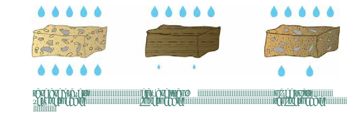
When coarse sand or gravel is put into a bucket of which the bottom is perforated and a cup of water is added on top of it, the water moves easily through the sand to the bottom of the bucket (fi g. 1). The water fl ows easily through the pores (open
space) between the grains. Conclusion; water easily fl ows through sand and gravel. Sand and gravel are thus very permeable.
When a well-screen is placed in a sand or gravel layer, the water fl ow through the sand into the well will be high, because the water easily fl ows through the sand to the well-screen (fi g. 2). However, when drilling with water pressure (see paragraph 5.1) ‘working water’ also easily fl ows out of the bore hole into the sand layer.
Clay and loam
The opposite is seen with clay and loam. When wet clay is put in a bucket (compressed as in a layer of soil) and a cup of water is added, the water will remain on top (fi g. 1). Clay particles are very small (and ‘sticky’) as are the pore spaces between the
particles. Conclusion; Water does NOT easily fl ow through clay. Clay is therefore described as not permeable or impermeable.
If a well-screen is placed in a clay layer, the water fl ow into the well will be very low (fi g. 2), (in this case, when drilling with water pressure (paragraph 5.1) no additives (par. 5.2) are necessary).
Particle name Particle size
Clay < 0.004 mm
Silt 0.004 – 0.06 mm Sand (fine, medium,
coarse)
0.06 – 2 mm Gravel and pebbles 2 – 64 mm Stones and boulders > 64 mm
Figure 1 ; blue is water, white is soil
Mixed formations
In most cases the formation consists of a mixture of clay, silt, and sand or gravel particles. For example, clay and sand (sandy clay) can exist as a homogeneous layer (clay and sand are mixed) or in alternating thin layers (layered; small sand and clay layers on top of each other). When those soils are put in a bucket and a cup of water is added, the water slowly fl ows through the soil (fi g. 1).
Conclusion: Water fl ows slowly through mixed soils and they are therefore described as semi permeable. When a well-screen
is placed in a mixed or layered layer, the discharge of the well will be low (fi g. 2).
Field ‘tricks’
Sometimes it might be diffi cult to determine the diff erence between permeable or impermeable layers.
This is a small trick to help you:
Take a representative sample of the soil (paragraph 4.2) and squeeze it into a ball, between your hands. Then drop the ball from a height of one meter above ground level. The ball falls down on the ground.
1. If the ball consists of non cohesive (non-sticky) particles, the ball totally falls apart. In this case the material is permeable.
The particles of sand or gravel will be easily visible.
2. If the ball falls apart only partially, the soil contains some silt or clay and sand. The formation will have a low
permeability.
3. If the ball only deforms and/or remains more or less in shape, it is composed of clay, and is described as impermeable.
Porosity
Sedimentary layers consist of many particles such as sand, silt and clay. Between these particles there is still a lot of open space called pores. The porosity is a measure for the percentage of free space in the formation. A porosity of 30% means that 30% of the total volume of the sample is open space while the remaining 70% is fi lled with particles. The pores can be fi lled with air or water.This does not always mean that the water easily fl ows through the soil. For example, clay has a high
porosity, but low permeability.
sand and gravel, clay and loam, mixed soil, very permeable impermeable semi permeable
Turbidity
Turbidity is a diffi cult word for the cloudiness of water, caused by very small particles
in the water (called suspended particles), rather like smoke of a fi re in the air. Clay and silt-sized particles are very fi ne. When these particles are found in water they cause it to be turbid or cloudy. If well water is extracted from a clay or silt layer, some of the fi ne particles in the formation may be transported by the fl ow and get suspended (mixed) in the water. As a result the water will look cloudy.
Conclusion
Always continue drilling until a large permeable layer (sand or gravel) is reached and install the entire well-screen in this
layer. If the layer is permeable, the water fl ow to the well will be high (the yield of the well will be high). In addition, when the layer consists of sand and does not contain very small particles, the water will be very clear (not turbid).
Bottles of water showing low and high turbidity
2 HYDROLOGY
2.1 HYDROLOGY
Hydrology describes the cycle of water as it rises from the sea and the earth’s surface as water vapor. This vapor forms
clouds, which fall somewhere else to the earth as rain. Part of the water penetrates in the ground and becomes part of the groundwater while another part fl ows through streams and rivers, back into the sea. From here the whole cycle can start all over again.
For drillers it is important to know in particular about the location and movement (fl ow direction) of groundwater in permeable water bearing layers (aquifers), and factors aff ecting the quality of groundwater.
2.2 GROUNDWATER FLOW
Just as surface water moves in a river, also groundwater fl ows (although much slower)
through the pores and cracks of the formation (groundwater does not stand still). It
is not always easy to determine the fl ow direction of groundwater. Still it can be of
great importance for the water quality of the well to know in which direction the
groundwater is fl owing and where the groundwater came from. Imagine a latrine
close to a well which is to be used for drinking water. The last thing you want is that
bacteria, viruses and parasites (disease-causing micro-organisms called pathogens),
originating from the latrine, will fl ow together with the groundwater to your well (par. 3.1, latrines).
Although it can be diffi cult to detect the fl ow direction without detailed surveys, in the
case of shallow groundwater, examination of the landscape can help. For instance, when a latrine is located on the slope of a hill or a mountain, the groundwater (contaminated with bacteria) is likely to fl ow in the same direction as the slope of
the hill. In this case it would not be good to place the well down-slope(downstream)
of the latrine, but rather on the same level or higher up (up-slope) of the latrine.
2.3 AQUIFERS
The word ‘aquifer’ simply means ‘a water bearing layer’. A good aquifer for the
installation of a well-screen is a permeable layer below the groundwater table
(par. 1.3). During drilling you may come across diff erent aquifers at diff erent depths,
separated by impermeable layers.
Phreatic aquifer
The upper aquifer is called the ‘phreatic’ aquifer. Rainwater directly infi ltrates the
soil. The water moves down and when it reaches the water level it is added to this aquifer. The water can take contamination (such as bacteria or pesticides) down into the groundwater. Therefore a phreatic aquifer is prone to pollution from activities
taking place on surface (par 3.1). Phreatic groundwater exists in a permeable layer
above an impermeable layer. If this phreatic groundwater layer is just a few meters
thick, it may run dry during the dry season, leaving your well empty.
Second aquifer
The next aquifer, covered by an impermeable layer on top (for example, a clay
layer) is called the ‘second’ aquifer. The impermeable layer above this water
bearing layer forms a barrier for bacteria and pollution and prevents them from traveling down to the second aquifer (please, see par. 3.2!).
! If there is a second aquifer present, it is generally best to install the well-screen in this second aquifer.
Below the second aquifer again an impermeable layer and a third aquifer may be present.
One aquifer
Sometimes only one aquifer is present. In this case it is recommended to drill as deep as possible to prevent bacteria and pollution from entering the well. Drilling deep also reduces problems of wells drying up because of seasonal fl uctuations (diff erence between wet and dry season) of the water table.
! For further explanation and important information on aquifers and hygiene, see chapter 3.
One aquifer Diff erent aquifers
When the area is less hilly, a good indicator can be the presence of a gully, stream or river. Rivers always fl ow through the lowest-lying parts of the area. And groundwater in turn generally fl ows to rivers. Be careful: this only counts for a naturally present river, not for man made channels.
It is NOT preferable to construct the well down-stream of the latrine.
Catchment area
Groundwater is fed by the infi ltration of rain through the soil and it eventually fl ows to lower areas and rivers. Although this
might be diffi cult to see on the surface (without detailed investigations), always try to imagine where the groundwater would
fl ow to, especially during the dry season. On top of a mountain for instance, the groundwater level can drop dramatically during the dry season, because at that time the groundwater that fl ows out of the pores of the formation to lower areas is not replaced by infi ltrating water from rainfall. Only when the rains start the groundwater level will rise again.
2.4 SEA WATER INTRUSION
In coastal areas, a deeper aquifer could contain salty sea water. Also, during the dry season when the water table is lower, salty sea water could move inland. When
this happens it is called saltwater intrusion. Salt water is heavier than fresh water.
This means fresh water tends to fl oat on top of the salt water layer.
When a well is drilled in a coastal area where saltwater intrusion exists, the salty
water may move up, due to the suction of the well (see drawing).
Therefore in coastal areas, drilling deeper will NOT always be the best option.
Fresh water on top of salt water
Salt water intrusion
2.5 SALT, IRON AND MINERALS
Besides pollution from the surface (bacteria and chemicals, par 3.1) or salt from the sea (par 2.4), water can taste bad
or be damaging to health due to natural minerals in the aquifer. These minerals have been present since the formation of
the diff erent geological layers and are now dissolved in the groundwater. Some well-known examples of natural minerals (natural chemicals) in groundwater are Calcium, Chloride, Carbonate, Arsenic, Fluoride and Iron, but many more exist. Some minerals, like Arsenic and Fluoride, can damage health badly and therefore a sample of the groundwater has to be analyzed in a laboratory to fi nd out if these chemicals are present. Luckily in most places concentrations of these minerals are low and so the water is safe for drinking.
Some examples:
Salt
When well water in a non-coastal area tastes salty, it is important to determine the origin of the salt. For example, if in the same area two other wells are drilled and completed, at diff erent depths (deeper or shallower), fresh (or less salty) water may be found (just taste the diff erence between the water from the diff erent wells). Look for diff erent colors or crystals in the soil samples; these may be the origin of the salt.
Iron
The same approach may help when iron is found in the water. Sometimes water has a bad metallic taste and the color of the water turns brown when it is left in a bucket or boiled. The water may create rusty looking spots on clothes and cooking material. This indicates the presence of high iron concentrations. The presence of high levels of iron may cause people to reject the water source. Iron is a very common element of groundwater.
Peat
When, during drilling, remains of old plants are found, it is recommended not to install a well-screen in this layer. Plant remains, below the water table, are decomposing very slowly and create an acidic environment. A common example is peat. Groundwater extracted from a peat layer smells like decomposed plant material, is very acid and looks brown (see photo).
Acidic groundwater (low pH)
The pH is a measure of the acidity of water. If the pH of the water is low the water is considered acid. In areas of acidic
groundwater (with a low pH) the acid in the water may cause corrosion to the steel and cast iron components (parts) of a hand pump. In such cases a type of pump made of PVC, plastic or stainless steel components may be considered.
Hard water (hardness of the water)
If water from the well has a high content of the minerals calcium (for example when drilling in limestone and chalk) and
magnesium it is called hard water. Hard water is generally not harmful (safe for drinking). However, it may give some problems
while washing your clothes: Soap lathers (gives foam) easily in soft water but not in hard water. In other words, if the hardness
of the water is high it may be diffi cult to use soap.
3.1 SITE SELECTION
Before the drilling of a new well starts, a good drilling site has to be found. In most cases the villagers or owner of the new
well will point out a location which is suitable for them as users. But this may NOT necessarily be the best location to get
the best quality of water! As a professional driller you will have the responsibility to inform your clients about hygiene and
the most hygienic location for the well.
There are two important aspects to keep in mind:
- The presence of sources of pollution such as latrines, waste (dump) areas, fi re places and fuel stations
- Sun or shade at the location of the well
Latrines
Some people may fi nd it practical to have their well constructed close to their house or latrine. Unfortunately, in doing so, they may not realize that a well close
to a latrine could be contaminated with (micro) organisms such as bacteria, viruses
and parasites. Some of these organisms can cause disease (like diarrhea) when the
water is used for drinking and are called pathogens. The pathogens from the human
waste in the latrines move downwards through permeable layers, and so locally
contaminate the groundwater (see fi gure 3). Although pathogens will not survive
long outside the human body, it will take a while before they die off completely.
Therefore groundwater close to latrines can contain living and harmful pathogens.
In selecting a good site for the well, it is recommended to construct the well NOT
down-stream or down-hill (par. 2.2) from a latrine. If it is diffi cult to determine the
groundwater fl ow direction, construct the well at least 30 meter away from the latrine.
Waste (dump) areas, farms, fi re places and fuel stations
The same applies to areas where waste is dumped and burned or where fuel or other
contaminants (for example pesticides or animal waste on farms) may seep into the groundwater, which then will become contaminated. Chemicals in drinking water can cause serious damage to health, (failure of body functions and deformations).
Sun or shade
While drillers may prefer to drill in the shade, it is NOT the best location for a well.
A lot of people will visit the well to fetch water, unaware that harmful pathogens
are traveling on the soles of their feet. For example the bacteria can be picked
from street refuse or from a latrine if someone has just been to the toilet. These
contaminants will be washed off the feet in the well surrounding, which is often wet. These contaminants are a threat to the quality of the drinking water. When a well is
placed in the shade, bacteria and algae will fl ourish (see photo).
If the well surroundings can dry up daily, the sunlight will disinfect the well
surroundings causing all pathogens to die.
3 HYGIENE IN RELATION TO GEOLOGY
3 Pollution of the aquifer
Presence of bacteria indicated by algae
3.2 MIGRATION OF PATHOGENS (BACTERIA)
As we have seen in the previous paragraph, pathogens (bacteria, viruses and parasites) and chemicals move downward with
the infi ltrating (rain)-water through permeable soil layers to the groundwater. Once in the groundwater the pathogens and
chemicals not only spread horizontally (left-right), but also vertically (up-down), deeper into the aquifer (see par. 2.3).
Different aquifers, fi gure 4
In par. 1.3 we have seen that groundwater easily fl ows through permeable layers
(aquifers) like sand and gravel. Pathogens and chemicals which are suspended (mixed
with) or dissolved in this groundwater also easily migrate (move) through permeable
layers!
Water with pathogens has to be stopped before reaching the surroundings of the
well-screen.Fortunately often impermeable layers can be found. Water, and thus the
pathogens in this water, does not easily fl ow through these impermeable layers. Due
to their fi ne texture (very fi ne particles), impermeable layers prevent pathogens
from further vertical migration down into the underlying aquifer. Because the
impermeable layer blocks the pathogens from downward migration, the next lower
aquifer contains water without the harmful pathogens and chemicals originating
from the surface. (fi g. 4).
One aquifer, fi gure 5
Sometimes however, only one aquifer exists within reach of manual drilling equipment, for instance a 50 meter thick permeable sand layer.
Although there is no impermeable layer in this case, further down into the sand layer the number of living pathogens will decrease gradually (every meter down, fewer pathogens will be present). It takes time for the pathogens to travel down and while doing so they die off over time.
However, there is no impermeable layer to prevent downward movement of pathogens and other contaminants, which marks the exact depth at which contaminants are not further present (fi g. 5). Therefore it is recommended to drill as deep as possible at locations where only ONE aquifer exists.
3.3 SANITARY SEAL
In the previous paragraph we have learned to drill through the impermeable layer to the second aquifer, in order to fi nd clean drinking water. But by doing so, a new problem is being created!
By drilling through the impermeable layer, a connection, (a short cut) is created between the fi rst and the second aquifer.
Drilling a hole through an impermeable layer is a little like taking the ‘plug out of the sink’, so enabling contaminants to fl ow down from the polluted layer to the clean, second aquifer and enter the well-screen (fi g. 6).
4 Bacteria migration in diff erent aquifers
When a borehole is drilled, a well-screen will be installed and a gravel pack placed (par. 6.5). Then the impermeable layer
has to be sealed (closed), to prevent contaminants from traveling down into the second aquifer. This is done by a sanitary
seal. The sanitary seal (par. 6.4) is made of cement or bentonite (natural clay which swells to many times its dry volume when
wetted) which will seal (close) again the impermeable layer (see fi g. 7).
When only ONE aquifer exists (fi g. 8), a sanitary seal with a thickness of at least 3-5 meter has to be installed above the gravel
pack, to prevent the contaminants from entering the well-screen (fi g. 9). Water (and pathogens) can travel faster down the loose material in the borehole than though undisturbed soil. An impermeable seal will force the water to fl ow through the normal undisturbed soil, thus increasing the traveling time (the pathogens die off over time) from the surface to the fi lter screen.
6 Bacteria migration in diff erent aquifers
7 Bacteria migration in diff erent aquifers with installed well and sanitary seal
8 Bacteria migration in one aquifer
and the borehole 9 Bacteria migration in one aquiferwith installed well and sanitary seal
! To prevent pathogens and chemicals from entering the fi lter screen and polluting the second aquifer a sanitary seal has to be placed (please see paragraph 6.4).
4.1 WHY DRILLING LOGS
In chapter 1 we learned to install our well-screen in a permeable layer. Chapter 2 showed the existence of diff erent aquifers. In
chapter 3 we have seen the necessity for the installation of a sanitary seal above the gravel pack (which surrounds the
well-screen) and/or to seal off the impermeable layer above the second aquifer. These are all important aspects of the construction
of a well with a good yield of clear and clean water, which is free of contaminants.
! It is therefore very important to determine the exact location (depth) of permeable layers (aquifers), and the location of any impermeable layers in our borehole!
To do this, simple but accurate drilling logs should be created. A drilling log is a written record of the geological formations
(soil layers) drilled, according to depth. Soil samples should be taken at regular depths (e.g. every meter) and described during the drilling process. The soil description is then recorded in the form of a drilling log. The drilling log will help us to determine:
1. The right aquifer for installation of the well-screen
2. Depth and length of the well-screen
3. Depth and thickness of the gravel pack
4. Location of the sanitary seal
Database
Besides the direct use of drilling logs in the fi eld, drilling logs are also very important to record the hydro geological information of the drill site. For example, if at a later stage other wells have to be drilled in the same village or area, it is very useful for the drilling team to know the geology, depth of the water table and likely total drilling depth. Previous drilling logs are an essential source of information for these purposes, before the new drilling starts. This information could be important for the choice of the drilling equipment. The drilling logs can be kept together in a fi le, which is called a database. By taking care to record and preserve good drilling logs, the drilling team will present itself as a professional and skilled team to their clients.
4.2 TAKING SOIL SAMPLES
The fi rst step in making a drilling log, is to take representative samples of the soil
(geological formations) encountered in drilling. This means: the sample should be a
pure piece of the layer that is being drilled at the moment of sampling (avoiding mixing the sample with soil from other layers!). Samples should be taken every meter and/or every time the formation (soil) type changes. The samples should be put on a plastic sheet (write down the depth if the sample is not immediately described), away from the drilling activities. Then described and recorded on the drilling log (see appendix C) with the depth at which the soil sample was taken.
4.3 DRILLING DEPTHS
In the previous chapters we have learned to install a well-screen in a permeable layer (chapter 1), which is ideally an aquifer underlying an impermeable layer (chapters 2 & 3).
The fi nal drilling depth is reached when at least 4-6 meter has been drilled into a water bearing permeable sand or gravel layer.
It is then recommended to drill two extra meters for installation of the sump (see par.
4.5 and 6.2) and as a reservoir for paricles in the borehole, to settle down in, during
the well casing installation process (par. 6.5).
4.4 FILLING IN THE DRILLING LOGS
Step 1
Describe samples during every break in the drilling process and write down the depth, name and characteristics on the drilling log (see par. 1.3).
Step 2
Then, especially important for those who can not write, hatch the formation column and show the diff erence between permeable, semi permeable and impermeable layers by diff erent hatching.
Drilling log
Drawing Depth Description hard / soft Color(s)
(meter) of the formation fine / coarse of the sample
PVC Back- Formation
pipe fill type
1 Sand fine yellow/brown 2 Sand fine yellow/brown 3 Sand fine yellow/brown 4 Sand fine yellow/brown 5 Sand fine yellow/brown 6 Sand fine yellow/brown 7 Sandy Clay ……… brown 8 Sandy Clay ……… brown 8.5 Sandy Clay ……… brown 9 Clay compact grey 10 Clay compact grey 11 Clay compact grey 12 Clay compact grey 13 Clay compact grey 14 Clay compact grey 15 Sand coarse yellow 16 Sand coarse yellow 17 Sand coarse yellow 18 Sand coarse yellow 19 Sand coarse yellow 20 Sand coarse yellow 21 Sand coarse yellow 21.5 Sand coarse yellow 22 Sandy Clay ……… grey/brown 23 Sandy Clay ……… grey/brown
……… ……… ……… ………….
By hatching, now the permeable, semi permeable and
impermeable layers become visible. Following hatching
styles are used:
Permeable Low permeable Impermeable
Drilling log
Drawing Depth Description hard / soft Color(s) (meter) of the formation fine / coarse of the sample
PVC Back- Formation
pipe fill type
1 Sand fine yellow/brown 2 Sand fine yellow/brown 3 Sand fine yellow/brown 4 Sand fine yellow/brown
∨ 5 Sand fine groundwater
6 Sand fine yellow/brown 7 Sandy Clay ……… brown 8 Sandy Clay ……… brown 8.5 Sandy Clay ……… brown 9 Clay compact grey 10 Clay compact grey 11 Clay compact grey 12 Clay compact grey 13 Clay compact grey 14 Clay compact grey 15 Sand coarse yellow 16 Sand coarse yellow 17 Sand coarse yellow 18 Sand coarse yellow 19 Sand coarse yellow 20 Sand coarse yellow 21 Sand coarse yellow 21.5 Sand coarse yellow 22 Sandy Clay ……… grey/brown 23 Sandy Clay ……… grey/brown
……… ……… ……… ………….
Cuttings Sanitary seal Gravel pack
Blind PVC casing pipe and sump Well-screen
In this example a 6 meter well-screen was installed between
15 and 21 meter below ground level. And a 1.5 meter sump
was attached to the bottom end of the well-screen.
Let us assume the groundwater level * is at 5 meter below
ground level. In this example we can see a second aquifer between 14 and 21.5 meter.
Step 3
Now the well-screen length and depth can be determined,
which is further explained on the next page, in paragraph 4.5.
Step 4
Once the well-screen and PVC casing are hatched in the
fi rst column, the exact depths for the annular backfi ll (i.e.
gravel pack, sanitary seal and cuttings) can be determined
by use of the drawings on the drilling log.
Drilling log
Drawing Depth Description hard / soft Color(s) (meter) of the formation fine / coarse of the sample
PVC Back- Formation
pipe fill type
1 Sand fine yellow/brown 2 Sand fine yellow/brown 3 Sand fine yellow/brown 4 Sand fine yellow/brown
∨ 5 Sand fine groundwater
6 Sand fine yellow/brown 7 Sandy Clay ……… brown 8 Sandy Clay ……… brown 8.5 Sandy Clay ……… brown 9 Clay compact grey 10 Clay compact grey 11 Clay compact grey 12 Clay compact grey 13 Clay compact grey 14 Clay compact grey 15 Sand coarse yellow 16 Sand coarse yellow 17 Sand coarse yellow 18 Sand coarse yellow 19 Sand coarse yellow 20 Sand coarse yellow 21 Sand coarse yellow 21.5 Sand coarse yellow 22 Sandy Clay ……… grey/brown 23 Sandy Clay ……… grey/brown
……… ……… ……… ………….
Note: This drilling log is designed to be fi lled in by both people who can write and who cannot write. The drawings are intended to assist in visualizing the geological layers and well completion details.
! Using the drilling log and drawing, the soil types (i.e. permeable, low permeable and impermeable) will therefore simplify determination of the exact location for the well-screen and annular backfi ll.
To resume: fi lling in the drilling logs is a 4 step process:
1. Describe the samples and depth
2. Indicate permeable and impermeable layers
3. Mark the casing, screen and sump in the column “PVC pipe”
4. Mark the backfi lling and sanitary seal(s) in the column “backfi ll”
* Groundwater level
When a borehole is drilled ‘dry’, meaning without the use of drilling fl uid, the depth of the water table can easily be determined during drilling. The soil that comes out during drilling will be wet when the groundwater level is reached.
With a fl uid-drilled borehole (see chapter 5), the borehole is kept full of water to maintain water pressure. In such cases, the groundwater level will not always be known from the hole drilled. It then can help to have local people indicate where the water table is likely to be on the basis of a hand dug well, other completed boreholes or river in the neighborhood.
In an area which is new to the drilling team it is advised to drill the fi rst well to the maximum possible depth (in a good aquifer), and measure and record the water level after the well construction.
4.5 DETERMINE THE DEPTH OF THE WELL SCREEN AND BACKFILLING
Once the soil descriptions are hatched on the drilling log, the visible information can be used to determine the exact depth of the well-screen and annular backfi ll. The drilling log shown above is used in the explanation below.
Well-screen, position and length
The well-screen usually does not exceed a length of 6 meter, for manually drilled boreholes. Fine materials are often present
in the extreme upper and lower parts of an aquifer. Also thin clay layers might exist in the aquifer. To prevent the fi nes (which
may cause turbidity and pump damage) from entering the well-screen it is important NOT to install the well screen at the
same level as these fi nes in the aquifer. In other words; be sure that the whole screen length is installed in a permeable layer,
consisting of sand or gravel! To achieve this in some cases the screen length might be less than 6 meters (but should generally never be less than 3 meter, see par 6.2).
! Although carefully taken, the exact depth of origin of the soil samples might not always be accurate. To avoid fi nes from entering, it is wise to install the well screen and backfi ll with a safety margin of at least 1 meter. In the drilling log above, the well-screen was placed in the middle of the aquifer, leaving a 1 meter margin of sand
at each end.
Sump
After the installation and during the use of a well, some soil particles may still enter the well-screen. The bigger particles
(which can cause damage to the pump) settle down to the bottom of the well by gravity. To prevent loss of well-screen surface
area, a sump of 1-2 meter in length, with a closed bottom end is attached to the well-screen (for details on PVC casing and
Thickness of the gravel pack
Once the well-screen position is recorded (hatched) on the drilling log, the position and thickness of the gravel pack can
be determined. The annulus (open space) around the well-screen is fi lled with coarse sand or fi ne gravel of specifi c size (gravel pack), up to about 1-2 meter above the top of the well-screen. The extra meters are necessary because during the
development of the well, the gravel pack will settle (and shrink). It is therefore good practice to include at least 1-2 meter
safety margin above the well-screen during installation of the gravel pack (for details see par 6.3).
Thickness of the sanitary seal
When an impermeable layer is drilled through, it is advised to seal (close) again that whole impermeable layer with clay
(bentonite) or cement (par 3.3). To be sure the layer is sealed properly, the thickness of this seal should be at least 3-5
meter.
If no impermeable layer was found, and the well is thus placed in the fi rst aquifer, the sanitary seal should be installed directly
on top of the gravel pack (1-2 meter above the well-screen) and should have a thickness of at least 5 meter (for details see
par 6.4).
Cuttings
On top of the sanitary seal, backfi lling of the drilling hole is done by using the cuttings (soil which was drilled up during the
drilling process).
Sanitary top-seal
Also a sanitary top-seal of 3-5m thickness should be placed from 3-5m below ground to the surface (for details see par 6.5).
5 WATER PRESSURE AND DRILLING FLUIDS
5.1 DRILLING WITH WATER PRESSURE
In paragraph 1.2 we have seen diff erent manual drilling techniques. Some techniques, like the auger and percussion methods, make use of a temporary casing when the groundwater table is reached, to prevent the borehole from collapsing during drilling. Other techniques, like sludging and jetting use water pressure.
Temporary casing
It is easy to understand how a temporary casing protects the hole from collapsing. The casing (pipe) is strong and acts like a wall. Soil from the sides of the borehole simply can not pass through the casing. However, the only drawback is that it has to
be removed afterwards (when the well-screen is installed). This can be very diffi cult
or it can even become impossible when a drilling was made through a clay layer (the casing can become stuck in the sticky clay).
Water pressure
While a casing pipe is strong and solid, water is just soft and liquid. How is it then possible for water to hold open a borehole while drilling in wet sands?
To fi nd the answer to this question, let’s fi rst take a close look at an example we all
know; A bag of water.
1. Fill a transparent bag (long) with water, for instance one of those drinking water bags which are commonly sold on the street (see photo). Now squeeze the lower part of the bag between your thumb and fi ngers. It takes very little eff ort to press the plastic inwards. Then again release the bag. As you see, the plastic returns to its former shape. What happened?
The weight of the water in the upper part of the bag pushed the plastic bag back into its former shape. What you just felt is water pressure.
2. Now put the bag in the middle of a bucket and fi ll the bucket with very wet sand to one third the height of the plastic bag (so that two-thirds of it emerges above the sand). Pour water into the bucket until the water level is just on top of the sand. The wet sand in the bucket simulates the aquifer. The hole and our plastic bag simulate the borehole. What is happening?
The weight of the water in the upper part of the bag is pushing against the sides of the plastic bag. Due to this pushing (pressure) the bag remains in shape and holds back the sand in the bucket by water pressure.
3. Next cut the plastic bag with a pair of scissors at the same height as the water level in the bucket. You will see that the borehole collapses. What happened?
By cutting the bag, the weight of the water from the upper part of the bag is no longer present, and cannot push against the plastic any more. The water level in the bag is now equal to the water level in the bucket. There is no additional water pressure.
A bag of water
Simulation of water pressure in the ‘borehole’ (bucket)
Borehole
We have seen how to ‘keep open’ a hole in wet sand when the sand was in a bucket. But how does it work in a borehole during drilling?
Cross section of the bucket Cross section of the borehole
The drawing on the left shows a cross section of the bucket with wet sand and a plastic bag. On the right, a cross section of the borehole is shown. Let us compare our ‘bucket’ borehole with the ‘real’ borehole;
1. The water level in the bucket represents the water table in our borehole.
2. The upper part of the plastic bag, above the water level in the bucket, is similar to the part of the borehole, fi lled
with water, which lies above the groundwater table.
3. The wet sand in the bucket represents the water bearing sand layer in the aquifer.
However, the plastic bag is absent in the real borehole. In the bucket we have seen that when the plastic bag was cut (the result was that the water level in the simulated borehole and the bucket became the same), the simulated borehole collapsed. In other words,
! If the water level in a real borehole falls towards (and becomes equal to) the water table, the borehole might collapse, especially when the drilling is done in gravel or sand (non-cohesive materials). To avoid collapse, it is necessary to keep the drilled borehole full of water during drilling and construction of the well.
To prevent our ‘working water’ (the water in the upper part of the borehole) from seeping away into a sand or gravel layer,
a substitute for the plastic bag is needed so that we do not loose our water pressure! For this reason drilling fl uid additives are
5.2 DRILL FLUID ADDITIVES
When an additive is mixed with our working water (drilling fl uid) and circulated through the borehole, the walls of the
borehole become plastered, like paint on a wall. This ‘temporary plaster’ plays the same role as the plastic bag, in the
example of the bucket. Additives also make the drilling fl uid more viscous (thicker), so that it is better able to carry cuttings upward from the borehole.
A number of possible drilling fl uidadditives exist:
- Bentonite
- Other natural clays
- Polymers
- Cow dung
- Fibers (and other solids)
Bentonite
Bentonite is a treated natural clay, which, when mixed with water, will increase the viscosity of the working water. In most
countries bentonite is expensive.
Advantage: Bentonite works extremely well
Disadvantage: Once the bentonite has plastered the borehole wall, it is very diffi cult to remove it and has to be
removed by chemicals or heavy pumping equipment during the well development. If the bentonite is not
properly removed, it can badlyaff ect the discharge of the well! Therefore it is NOT recommended to use
bentonite for manual (low cost) drilled boreholes. In some countries its use as a drilling fl uid additive is not permitted.
Other natural clays
Natural clay, found during drilling, in termite hills or elsewhere, works like bentonite (only less sticky). Natural clay is cheap,
but shares the same disadvantage as bentonite: It clogs up the aquifer.
Polymers
The best working water additives are polymers. When mixed with water, they
thicken the working water into a veryviscous fl uid. Natural polymers are also used
as stabilizers and thickeners in the food industry.
Advantage: Polymers work extremely well and natural polymers are
biodegradable. In other words, they disappear naturally in a few days time.
Disadvantage: In most countries they are diffi cult to obtain and rather expensive.
Although expensive, polymers are recommended for manually drilled boreholes. Further research on low cost natural polymers will be done shortly, by the publisher of this manual.
Fresh cow-dung
It might sound dirty, but fresh cow-dung shares many of the advantages of natural polymers. It works extremely well and is biodegradable. Besides, fresh cow-dung is
widely available in most countries and very cheap to get.
However, there is resistance to the use of cow-dung for water well drilling purposes.
Cow-dung also contains the E-coli bacteria(and other animal pathogens par 7.3).
The E-coli bacteria is used as an indicator for the presence of fecal contamination (bacteria coming from latrines) that can cause human disease.
Studies so far have shown that cow-dung (indicated by Nitrates) and E-coli both disappear within a few weeks after the construction of the well. However, still more work needs to be done on the health and safety implications of the use of cow dung. It is generally recommended that a newly drilled well in which cow-dung
has been used is not used for drinking during the fi rst month of operation
Advantage: Cow-dung works extremely well, is biodegradable, cheap and widely available.
Disadvantage: Carries animal pathogens. Chlorination of the well after development and test pumping is recommended.
Further research in the health aspects of use of cow-dung will be done shortly by the publisher of this manual.
Fibers and other solids
To increase the eff ectiveness of additives in coarse sand and gravel aquifers, fi bers and other solids can be mixed in with the drilling fl uid. These materials block the pores of coarse layers and help, together with the additives, to prevent working
water loss. However, fi bers are diffi cult to remove. Use of fi bers is therefore not recommended in the ‘well-screen zone’ of
the borehole. Typical examples of fi bers are: sawdust and grain husk.
5.3 REMOVAL OF ADDITIVES FROM THE BOREHOLE
After the drilling and installation of the well-screen and casing the drilling fl uid additives have to be removed to maximize
the yield of the well. This is done by rinsing, surging and over-pumping of the well in the process known as welldevelopment
(chapter 7).