DOI: 10.12928/TELKOMNIKA.v17i1.11615 291
Reference broadcast synchronization and time division
multiple access implementation on WSN
Sabriansyah Rizqika Akbar1, Mochammad Hannats Hanafi Ichsan*2, Aulia Arif Darmawan3
Faculty of Computer Science, University of Brawijaya, VeteranSt., Malang, East Java, Indonesia telp/fax: +62 341 551611/+62 341 565420
*Corresponding author, e-mail: [email protected], [email protected]2, [email protected]3
Abstract
Various kinds of technology have been developed to assist obtain information. One of them is a Wireless Sensor Network (WSN). WSN is a wireless network consisting of multiple nodes connected wirelessly. WSN nodes on a device have small resources in the form of batteries. The main problem which owned by WSN was in the data collection process possible collisions data, there are nodes that transmit data at the same time. Time Division Multiple Access (TDMA) was able to provide data on the delivery schedule of each node. So no nodes that transmit data at the same time. But in order to apply the system each node should have equal time. One method that able to provide equalization time was Reference Broadcast Synchronization (RBS). This method synchronizes multiple nodes that have different local time (on the receiver) with the help of node that provides synchronization marks (beacons). Hence this each node was able to transmit data in accordance with the TDMA method that has been implemented. In addition time synchronization performed using RBS give equal time with accuracy up to microseconds. That case certainly makes the WSN node able to provide accurate information to guarantee the absence of errors due to data collisions. This research succesfully sending data delivery schedule by time slots that provided by RBS and time synchronization by TDMA average time delay 2285.9 microseconds.
Keywords: RBS, TDMA, time synchronization, WSN
Copyright © 2019 Universitas Ahmad Dahlan. All rights reserved.
1. Introduction
Many technologies developed to assist people to obtain information. One technology that is now developing was Wireless Sensor Network (WSN). WSN is a wireless network consisting of nodes that form a network. The node on the network was a device that is small, inexpensive, and battery-powered so it has limited resources and is equipped with sensors and communication modules [1]. WSN can be used for environmental, seismic, navigation, forest monitor etc. [2]. Node strategically placed in the desired region and tasked with monitor, detect, provide information and communicate [3]. WSN built by several components such as sensors, wireless module etc. [4]. One of the important features of on WSN is the collection of data [5], which is collected sensor data from multiple nodes transmitted via wireless communication node to the sink. But the problem in [6] is how this data can be transmitted to the sink node without loss of information due on delivery of broadcast and WSN is a working on the same frequency. Conceivably, if a situation node sends data simultaneously, of course, this makes data collisions resulting data cannot be accepted and the information could not be obtained. To deal with these issues, on WSN can be given a schedule of data transmission. So that there are no nodes that transmit data simultaneously which resulted in the collision data. To support the provision of schedule on each node in a network, each node should have equal time. The local time between each node did not have a lot of time difference.
One of the methods for equalizing time is Reference Broadcast Synchronization (RBS). RBS synchronize one receiver with other receivers. In [7] RBS works with a headless node synchronization (beacon), this node periodically sends packet node reference to a broadcast receiver. Each node such as Receiver node and Sender node using Arduino Pro Mini as Microcontroller and Transceiver Module using nRF24L01 as communication modules. The receiver uses packet arrival time as reference points to compare them with the local time when the local node other receivers. RBS used because first it can reduce timing at critical path so it would increase the accuracy [8], the second is reference nodes would change periodically due to
synchronization performed using RBS give equal time with microsecond accuracy up to unit [7]. That case certainly makes the WSN node able to providing accurate information to guarantee the absence of errors due to data collisions [12]. This research is expected to produce a system that able to provide guarantees in terms of the delivery-acceptance of information on WSN. This research focused to integrate RBS and TDMA on WSN, so it can measure how reliable the algorithm when implemented on WSN.
2. System Design
This research focused on the sink node on sensor field. Each node has a purpose of collecting data called sink node [13, 14], it describes the illustration of WSN architecture [15, 16]. One from several sink node could communicate to the internet that called gateway. Prior to system development, will be made by the design of the network topology, RBS method, the method TDMA, Beacon Node, Node configuration and design Receiver Frequency and Channel that will be used in systems integration.
2.1. Network Topology
In this study, the node is divided into two, the beacon node and the receiving node. Node serves as a marker beacon time synchronization and data transmission destination node after scheduling. While the receiving node is the vertices of the subject and sender data synchronization. Each node builds a network and can communicate directly with other nodes (single hop) was designed. Each node, beacon or receiver node using Arduino Pro Mini and nRF24L01 as transceiver module.
The workflow system starts by activating each node. Especially for the receiving node given local time respectively. Which was first performed by the beacon node sends a packet synchronization reference or mark packets to each recipient node [17]. Then the receiving node stores packet arrival time (time of observation). Furthermore, the receiving node exchanging observation time and calculate the time difference. After knowing the time difference, each node performs the equalization process time with the local time of each node with the time difference. Last node receiver alternately transmits data in accordance with the schedule that has been given. The only node that carries out and gives commands for completion is the beacon node. When the system starts to work, each receiving node has its own local time that has local time different from another receiving node. Then all other nodes after the beacon node give commands to configure using reference packages. While the receiving node receives the packet arrival time of the reference packet, recorded conform local time each receiver node called the observation time, reference illustration package delivery contained in Figure 1 (a).
The next stage is the synchronization carried out by each recipient node, where each recipient node exchanges addressing time with another node. This is because the receiving node synchronization among others, beacon nodes do not participate in the exchange of this observation period. While the exchange of data in stages starting from the receiver relay node 1 to the receiving node 4 as shown in Figure 1 (b). Exchange of observation time done in order to each node knows the time of receipt of the packet receiver reference other nodes. So it can determine time differences or phase offset from another node receiver.
Figure 1. (a) Beacon node reference package delivery (b) package delivery time observation
2.2. Beacon Node Algorithm Design
Node beacon worked as a giver package receiver reference package receiver being used to synchronize time and as the recipient of the packets from the receiver after scheduling as shown in Figure 2. On that figure, the node beacon works and send packets according to the desire of the users. After the node beacon sends accordance amount is entered. Then node beacon waits until the synchronization is complete, followed by a change to the reception mode to receive all packets from receiver node.
Figure 2. Beacon node flowchart
2.3. Receiver Node Design
Synchronization using RBS method, the receiver node has a role as a synchronization object. Where receiver node synchronizes the time with another receiver, the beacon node is not synchronized. The following flowchart synchronization algorithm which performed each node receiver. As the flowchart on Figure 3, workflows receiver node starts after getting a reference packets from node beacon. Node saves time acceptance of package as used at the time of observation time synchronization RBS. After synchronization is complete occurs scheduling using TDMA. Then each node receiver data transmission according to the schedule set.
Figure 3. Receiver node flowchart 2.4. Reference Broadcast Synchronization (RBS)
Time synchronization a way to make the same timescale used by each device in the network. RBS synchronization has a node acting as the sender so-called beacon node and multiple nodes that act as a receiver node. Beacon node is a node that provides a reference to the package receiver [18]. After offset value was obtained, time synchronization process can be done with a local value time offset. How it is done up to the last node to the first node time synchronization is complete. Explanation Figure 4 that flowchart synchronization work after the receiver node receives a reference packet, node receiver stores the time of receipt of the package and serve as the time of observation. Then proceed delivery of packets between nodes of observation time receiver.
The first node with id gets a turn sends the packet to the first node while the other receivers in the reception mode. In the reception mode node computes phase offset by subtracting the time of observation any other node with a time of his own observations, and if obtained phase offset is less than 0 and less than the offset phase before it which used as a phase offset is offset new phase. This process is done until all id finished sending packet observation time. Then each node to synchronize time by subtracting the local time with phase offset.
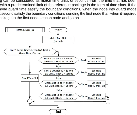
2.5. Time Division Multiple Access (TDMA)
TDMA is a technique of media access that allows multiple nodes to transmit packets on the same channel [19]. The channel access time periods alternately conform (time slot) which given to each device, so it will not happen package delivery simultaneously resulting collision the data [11]. Data transmission takes place according to a predetermined time slot. Node 1 can transmit data at a time slot to node 1, node 2 can send the form data in the time slots to node 2, and so on. Sidelines of the time slots are usually given time guard which is useful for time transition mode of each node. Illustration of time slots can be seen in Figure 5.
Figure 5. Illustration of TDMA time slot
Data transmission takes place according to a predetermined time slot. Figure 5 explained that one node able to transmit data at a time slot to node 1, node 2 able to send the form data at a time slot to node 2, and so on. The sidelines of the time slot are usually given guard time which is useful for mode transition time of each node. In Figure 6 described TDMA scheduling stage, this scheduling can be considered as match time units of seconds from the time that has been synchronized with a predetermined limit of the reference package in the form of time slots. If the second time node guard time satisfy the boundary conditions, when the node into guard mode (idle). While at second satisfy the boundary conditions sending the first node than when it required sending the package to the first node beacon node and so on.
number of test nodes ranging from 1, 2, 3 and 4. So that the number of packets sent 5 can be received per node is also 5 so it is denoted by 5/5 as well as another testing scenario.
Table 1. Quality Test Result
Test Number Reference
Packet Number of Nodes 1 2 3 4 1 1 1/1 1/1 1/1 1/1 2 2 2/2 2/2 2/2 2/2 3 3 3/3 3/3 3/3 3/3 4 4 4/4 4/4 4/4 4/4 5 5 5/5 5/5 5/5 5/5 6 6 6/6 6/6 6/6 6/6 7 7 7/7 7/7 7/7 7/7 8 8 8/8 8/8 8/8 8/8 9 9 9/9 9/9 9/9 8/9 10 10 10/10 10/10 10/10 10/10
Based on Quality test scenario, it conducted by 10 times with 10 different reference packet. The testing conducted by 10 reference packet because the process of sending data at one time, will not be more than 10 packets. Therefore enough testing is done with a maximum of 10 packets. The second is a test to see the readiness between each node receiver in sending and receiving packets observation time alternately. Starting from the first node package delivery until the last node. When one node to another node to send data, it must be in a state of receiving the package. Table 1. produces a result where from each test performed from 1 to 4 nodes, the reference packet can be delivered properly. From 1 reference packet to 10 reference packets, all reference packets can be sent and received properly.
3.1. Time Synchronization Results
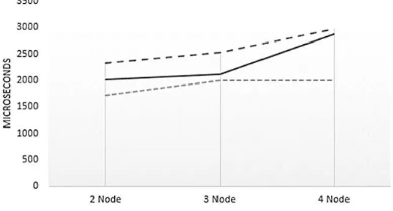
This test is done to look at the error rate time of time synchronization using RBS. On the basis of the influence of the number of nodes and the number of packets used in the reference time synchronization. The number of nodes in this study is 2-4 while the number of reference packet transmitted is 1,5,10. Graphs are plotted by the horizontal axis representing plenty of references packets are sent while the vertical axis represents the value of the error. 1 reference packet with 2 nodes, consuming bigger time than 4 nodes with 10 reference packet.
While average value represented by coordinate points connected by a line in Figure 7. There can be analyzed that with the increase of nodes in synchronization, adding time synchronization error. This is because the load of increased synchronization that each node must compare more time to synchronize the time of observation. But in contrast with the increase in the reference packet that is sent to reduce error rates synchronization time. This is because plenty of packages making reference node can perform sampling time of reception which more so the average time is better than which using fewer reference package. The bigger reference packet that sent it will be increasing time synchronization.
Figure 7. Testing result
In Table 2 the tests performed by detail described by a graph representing the results of the average value of time synchronization. Each Reference Packet was sent 10 times, an example at 2 nodes (average) with 5 Reference Packet is 2015.6 that is average that conducted by 10 times testing.
Table 2. RBS Test Results
2 Node 3 Node 4 Node
Reference packet 1 2336.5 2521.7 2975.7 5 2015.6 2121.4 2873.5 10 1726.5 2000.2 2002.1 Average (microsecond) 2285.9 3.2. Scheduling Results
Scheduling testing was conducted to see the suitability of the data transmission node receiver by a predetermined schedule by TDMA. In this test, there are 4 types of time slots that 2, 3, 4 and 5 (in seconds). At each time slot has time tolerance for 1 second that is useful for delivery mode transition to the reception mode. Testing is done by looking at the data transmission from each node for 30 seconds.
From the testing that has been done, no collision of data on packet delivery from the receiver to the beacon can be seen in Table 3. This happens because each node sends data in accordance with the schedule determined by the method of TDMA. Besides the transition time is also useful to tolerate an error of time synchronization. So that the error contained in time synchronization RBS does not interfere with the delivery schedule. After time synchronization with RBS, the node could send data using the time that provided by TDMA mechanism. Due to that condition, the collision of data that sent never happens. Because of the data sending scenario based on the time that given by time slot by each node.
Table 3. Scheduling Test Result
Testing Trial Amount of Nodes
2 3 4
Time Slot
2 Succeed No Error Succeed No Error Succeed No Error
3 Succeed No Error Succeed No Error Succeed No Error
4 Succeed No Error Succeed No Error Succeed No Error
5 Succeed No Error Succeed No Error Succeed No Error
4. Conclusion
Based on this study, testing and analysis, it can be concluded that this system can work well in terms of sends and receive data. Based on the results of RBS synchronization, the number of nodes that must be synchronized would increase time error result of each node, but the number
[1] Yick J, Mukherjee B. Wireless Sensor Network Survey, Computer Network–Elsevier. 2008; 52(12): 2292–2330.
[2] Mukhtiar Ahmed, Mazleena Salleh, M Ibrahim Channa, Mohd Foad Rohani. Energy Efficient Routing Protocols for Underwater Wireless Sensor Networks: A Review. TELKOMNIKATelecommunication
Computing Electronics and Control. 2017; 15(1), 202-209.
[3] Akyildiz IF, Su W, Sankarasubramaniam Y, Cayrici E. Wireless sensor networks: a survey, Computer
Networks-Elsevier, 2002; 38(4), 393–422.
[4] MY Hariyawan, A Gunawan, EH Putra. Wireless Sensor Network for Forest Fire Detection,
TELKOMNIKATelecommunication Computing Electronics and Control. 2013; 11(3), 563-574.
[5] Francesco MD, Das KD, Anastasi G. Data Collection in Wireless Sensor Networks with Mobile Elements. ACM Transactions on Sensor Networks (TOSN). 2011; 8(1): 7.
[6] Ye F, Zhong G, Lu S, Zhang L. Gradient broadcast: a robust data delivery protocol for large scale sensor networks. Journal Wireless Networks Springer-Verlag. 2005; 11(3), 285-298.
[7] Elson J, Girod L, Estrin D. Fine-Grained Network Time Synchronization using Reference Broadcasts. UCLA Computer Science Technical Report, Boston, 2002.
[8] Qiu T, Zhang Y, Qiao D, Zhang X, Wymore LM, Sangaiah AK. A Robust Time Synchronization Scheme for Industrial Internet of Things. in IEEE Transactions on Industrial Informatics. 2017. [9] D Djenouri, R4syn: Relative referenceless receiver/receiver time synchronization in wireless sensor
networks. IEEE Signal Process Lett. 2012; 19(4), 175-178.
[10] AS Syed Navaz, GM Kadhar Nawaz. Layer orient Time Domain Density Estimation Technique based Channel Assignment in Tree Structure Wireless Sensor Networks for Fast Data Collection.
International Journal of Engineering and Technology (IJET). 2016; 8(3): 1506-1512.
[11] Chu Y, Kosunalp S, Mitchell PD, Grace D, Clarke T. Application of reinforcement learning to medium access control for wireless sensor networks. Engineering Applications of Artificial Intelligence. 2015; 23-32.
[12] Alam MMA, Berder O, Menard D, Anger D, Sentieys O. A hybrid model for accurate energy analysis of WSN nodes. Journal EURASIP Journal on Embedded Systems. January 2011; 2011(4).
[13] Lu G, Krishnamachari B, Raghavendra CS. An Adaptive Energy-Efficient and Low-Latency MAC for
Data Gathering in Wireless Sensor Networks. in Proceedings of the 18th International Parallel and
Distributed Processing Symposium (IPDPS’04). 2004.
[14] Wang F, Liu J. Networked Wireless Sensor Data Collection. IEEE Communications Surveys and
Tutorials. 2011; 13(4): 673-687.
[15] Tarek Al Skaif, Manel Guerrero Zapata, Boris Bellalta. Game theory for energy efficiency in Wireless Sensor Networks: Latest trends. Journal of Network and Computer Applications. 2015; 54, 33-61. [16] Yinbiao S, et al. Internet of Things: Wireless Sensor Networks, in International Electrotechnical
Commission, Geneva, Switzerland. 2014.
[17] Sivrikaya F, Yener B. Time synchronization in sensor networks: a survey. IEEE Network. 2004; 18(4), 45-50.
[18] Noh KL; Chaudhari QM. Novel Clock Phase Offset and Skew Estimation Using Two-Way Timing Message Exchanges for Wireless Sensor Networks. IEEE Transactions on Communications. 2007; 55(4), 766–777.
[19] Aji RF, Suhartanto H, Yazid S. A Sense-based Registration Process for TDMA in IEEE 802.11 Network. International Journal of Electrical and Computer Engineering. 2018; 8(1), 355-359.
[20] Yashchenko VN, Kozlov DS, Vendik IB. Dual-Mode Resonator for The Dual-Band System Of Wireless
Energy Transfer With Simultaneous Data Transmission. Progress in Electromagnetics Research