6
II
February 2018
Review on Study of Different parameters affecting
Heat transfer in Helical Coil Heat Exchanger
Amey P. Joshi1, Jayesh V. Bute2 1
(Student (Mechanical Engineering)/Pimpri Chinchwad College Of Engineering &Research, Pune, India) 2
(Asst. Prof. Pimpri Chinchwad College Of Engineering &Research, Pune, India)
Abstract: A heat exchanger is a device that is used to transfer thermal energy (enthalpy) between two or more fluids, at different temperatures and in thermal contact The tube diameter, tube length, shell types etc. are all standardized and are available only in certain sizes and geometry. Helical coil heat exchangers are one of the most common equipment found in many industrial applications. Helical coil heat exchanger is one of the devices which are used for the recovery system. The helical coil heat exchangers can be made in the form of a shell and tube heat exchangers and can be used for industrial applications such as power generation, nuclear industry, process plants, heat recovery systems, refrigeration, food industry etc. Helical coil Configuration is very effective for heat exchangers and chemical reactors because they can accommodate a large heat transfer area in a small space, with high heat transfer coefficients. Heat Transfer Coefficient is increased in helical coil heat exchanger due to centrifugal force generated in it. This force is generated due to secondary flow created in it.
Keywords: Helical coil heat exchanger, heat transfer, secondary flow, centrifugal force void friction, thermal performance factor
I. INTRODUCTION
In industries, heat exchangers are used in industrial process to recover heat between two process fluids. Shell-and-tube heat exchangers are the most widely used heat exchangers in process industries because of their relatively simple manufacturing and their adaptability to different operating conditions. But nowadays numbers of industries are searching for effective and less time
consuming alternatives of designing of shell-and-tube heat exchangers. It has been widely known fact that heat transfer rates in
helical coils are higher as Compared to those in straight tubes. Due to the compact structure and high heat transfer Coefficient, helical coil heat exchangers find extensive use in industrial applications. Helical coils of circular cross section have been used in wide variety of applications due to simplicity in manufacturing. Flow in curved tube is different from the flow in straight tube because of the presence of the centrifugal forces. These centrifugal forces generate a secondary flow, normal to the primary direction of flow with circulatory effects that increases both the friction factor and rate of heat transfer. The intensity of secondary flow developed in the tube is the function of tube diameter (d) and coil diameter (D). Due to enhanced heat transfer inhelical coiled configuration the study of flow and heat transfer characteristics in the curved tube is of prime importance. Developing fluid-to-fluid helical heat exchangers (fluid is present on both sides of the tube wall) requires a firm understanding of the heat transfer mechanism on both sides of the tube wall. Though much investigation has been performed on heat transfer coefficients inside coiled tubes, little work has been reported on the outside heat transfer coefficients.
Different parameters are also need to considered while installing heat exchanger
A. Logarithmic mean temperature difference (LMTD)
It is used to determine the temperature driving force for heat transfer in flow systems mostly in heat exchanger. It is given by,
Q= (dTA – dTB)/ln(dTA/dTB)
dTA= Thot in –Tcold out dTB =Thot out – Tcold in
It is the parameter which takes into account variation of temperature difference with respect to length, along the length of heat exchanger. Larger the LMTD more heat is transferred.
B. Exergy
C. Reynolds number
It is an important dimensionless quantity in fluid mechanics used to help predict flow patterns in different fluid flow situations.
Re=DVρ/μ
As Reynolds number increases heat transfer also increases as turbulence goes on increasing with it.
D. Overall heat Transfer coefficient
It is employed in calculating the rate of heat transfer from one fluid to other via solid surface. U= Q/A0ΔT
U is the parameter which takes into account all the modes of heat transfer. As U increases heat transfer also increases.
E. Nusselt Number
In heat transfer at a boundary within a fluid, Nu is the ratio of convective to conductive heat transfer across the normal. Nu = hd/k
A large Nusselt number correspondes to more convective heat transfer rate. As heat transfer coefficient is directly proportional to the Nusselt number, as heat transfer coefficient increase Nusselt number.
F. Prandtl Number
It is the dimensionless parameter used in the calculations of heat transfer between a moving fluid and a solid body. Pr = cpμ/k
Cp,μ,ρ,k = Fluid properties at avg. bulk temperature.
G. Fouling
The deposition of any unwanted material on heat transfer surfaces is named as fouling.Fouling decrease the heat transfer as it creates problem for the constant fluid flow.
H. Thermal Performance factor
It is the ratio of change in heat transfer rate to the change in friction factor. This factor always needs to be high.
II. LITERATURE REVIEW
The following research papers are studied in detail and the abstract of the work is presented here:
Pramod S. Purandarea, Mandar M. Leleb, Rajkumar Guptac in their paper “Parametric Analysis of Helical Coil Heat Exchanger ‘presented a comparative analysis of the different correlations given by the different researchers for helical coil heat exchanger. The
various equations use different parameters for the analysis. The overall effect of these parameters on Nu and hi is presented in this
paper. The analysis shows that, for low Re, the graphs of Nu VsRe and hi VsRe is steeper than that at high Re. It indicates that
helical coils are efficient in low Re.
J. S. Jayakumar, Amrita Vishwa Vidyapeetham in their paper investigated that Increase in pipe diameter, keeping the inlet velocity constant, causes higher heat transfer coefficient and lower pressure drop. This effect is due to the influence of secondary flows. As the PCD is increased, the centrifugal forces decreases and this causes reduction of heat transfer coefficient and pressure drop. Estimation of inner heat transfer coefficient for the two-phase flow was carried out by changing the void fraction and flow velocity. Results indicate reduction in heat transfer coefficient with increase in void fraction.
Surendra Vishvakarma, Sanjay Kumbhare, K. K. Thakur, E. Ibrahim in their paper ‘a review on heat transfer through helical coil heat exchangers’ concluded the Study of Forced Convection over Equilateral Triangle Helical Coiled Tubes in this experimental study he was focused on the investigation of the heat characteristics of an equilateral triangular cross-sectioned helical tube under uniform heat flux boundary condition. The experiments were performed using groups of equilateral triangles helical tubes. Nine helical coiled-tubes of equilateral triangular cross sectioned with various pitches and coil diameters are used.
dc/dt and dv/f) which maximize the hat transfer and minimize entropy generation rate (which are desired in design process) have been obtained.
Chirag Maradiya, Jeetendra Vadher, Ramesh Agarwal in their paper concluded that the heat transfer enhancement occurs in all cases due to reduction in the flow cross section area, an increase in turbulence intensity and an increase in tangential flow established by various types of inserts. Geometrical parameters of inserts like width, length, twist ratio, etc. affect the heat transfer enhancement considerably.
A. Terminology Of Helically Coiled Pipes
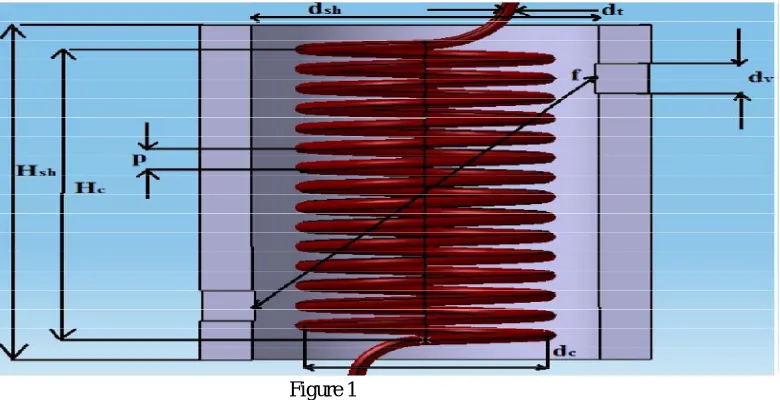
Fig. 1 gives the schematic of the helical coil. The thickness of the pipe is given as dt Diameter is represented by dc(measured
between the centres of the pipes). The distance Between two adjacent turns, called pitch is P. The coil diameter is also called as pitch circle Diameter (PCD). The ratio of pipe diameter to coil diameter is called curvature ratio, The ratio of pitch to developed length of one turn is termed non-dimensional Pitch,. Consider the projection of the coil on a plane passing through the axis of the coil. The angle, which projection of one turn of the coil makes with a plane perpendicular to the Axis, is called the helix angle. Consider any cross section of the pipe created by a plane passing through the coil axis. The side of pipe wall nearest to the coil axis is termed inner side of the coil and the farthest side is termed as outer side of the coil. Similar to Reynolds number for flow in pipes, Dean number is used to characterise the flow in a helical pipe.
Figure 1
B. Laminar-Turbulent Transition
The curved shape of the tube causes the flowing fluid to experience centrifugal force. The extent of centrifugal force experienced depends on the local axial velocity of the fluid particle and the radius of curvature of the coil. The fluid particles flowing at the core of the pipe have higher velocities than those flowing near to the pipe wall. Thus the fluid particles flowing close to the tube wall experience a lower centrifugal force than the fluid particles flowing in the tube core. This causes the fluid from the core region to be pushed towards the outer wall (away from the coil axis). This stream bifurcates at the wall and drives the fluid towards the inner wall along the tube periphery, causing generation of counter-rotating vortices called secondary flows. The secondary flows produce additional transport of the fluid over the cross section of the pipe. This additional convective transport increases both the heat transfer and the pressure drop when compared to that in a straight tube.
C. Influence Of Pitch Circle Diameter (Pcd) On Heat Transfer
The effect of PCD is to influence the centrifugal force on the moving fluid. This will in turn affect the secondary flows along the pipe cross section. As the PCD is increased, the effect of coil curvature on flow decreases and hence centrifugal forces play a lesser role in flow characteristics. For the coil with PCD=100 mm, the entrance effects are seen to be present up
[image:4.612.133.523.313.513.2]move to coils of higher PCDs, this difference comes down and for a coil of PCD=400 mm, itreduces to 134. Thus the effect of centrifugal force on heat transfer is evident.
D. Influence Of Pipe Diameter (D) On Heat Transfer
In this analysis, the effect of pipe diameter on heat transfer in a helical coil is considered. The pipe diameters considered for analyses were, 10 mm, 20 mm, 30 mm and 40 mm. For all these cases, coil has a pitch of 45 mm and PCD of 300 mm and the coil consists of two turns. For the coil with 10 mm diameter, Nusselt number in the top and bottom regions of the pipe are approximately equal. In the region of fully developed heat transfer, there is even uniform Nusselt number along the periphery of many planes. When the pipe diameter is low, the secondary flows are weaker and hence mixing is lesser. This produces nearly the same heat transfer in the upper half cross-section in a given plane. When the diameter of the coil is changed to 20 mm, in contrast to the case
where d=10mm, heat transfer at the outer side of the coil remain the highest for all of the sections. As expected, the length of pipe
needed for the heat transfer to attain a fully developed state has increased as the pipe diameter is increased. A straight line relationship is observed between Nusselt and pipe diameter. Regression analysis was carried out and the result verifies a linear
relationship between Nuav and pipe diameter.
E. Influence Of Void Fraction On Heat Transfer
After establishing the influence of coil parameters on two-phase flow and heat transfer, it is
necessary to understand the influence of inlet void fraction on the heat transfer. It is found that with an increase in void fraction, the two-phase heat transfer coefficient continuously decreases.
F. Influence Of Baffle Helix Angle On Pressure Drop And Heat Transfer
Flow resistance and heat transfer of heat exchangers with discontinues helical baffles are experimentally studied and compared at
five helix angles of 80,120,200,300,400.The results indicated that the pressure drop and heat transfer coefficients of the heat
exchanger with smaller helix angle are higher than those with larger helix angles. However in the condition of the same Reynolds number, the resistance to flow is lower with higher helix angle and heat transfer performance is more. The heat exchanger with
helical baffles at 400 helix angle presents the best comprehensive performance among the five tested heat exchangers.
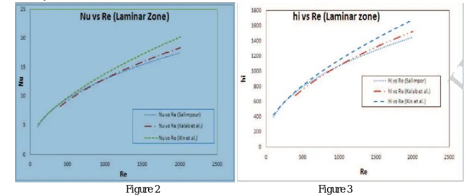
[image:5.612.69.532.440.634.2]G. Effect Of Reaynolds No On Nu And Hi In Laminar Zone
Figure 2 Figure 3
In laminar region, it is observed that Nu and hi increases with increase in Re. This shows that in laminar region the secondary’s
developed in the fluid flow goes on increasing, as Re increases, which increases the turbulence in the fluid flow. The increase in turbulence allows proper mixing of the fluid, which enhances the Nu and hi.
Helix Number (He) is calculated as
H. Effect Of Surface Characteristics On Heat Transfer
The baffles are used as an artificial roughness to create turbulence in the Heat exchanger so as to improve the heat transfer rate. Secondary flow is developed due to baffle which creates turbulence or swirl. Baffles with different shapes and geometrical configurations are used e.g. winglets, rectangular-shaped winglets, delta shaped wings, V-shaped wings and perforated baffles that can be attached and bent away from the plate to create turbulence in the flow field, which results in enhanced heat transfer in various engineering applications including heat exchangers, vortex combustors, and solar air channels among others. Various investigators have studied the heat transfer and pressure drop characteristics generated by baffle elements of various shapes, sizes, and orientations as an artificial roughness on a heated plate.
I. Effect Of Roughness
Roughness improves the heat transfer characteristics in a solar air heater duct. To determine the effect of roughness on small diameter pipe, experiments were performed by Kandlikar et al. (2003). They generated roughness by acid treatment. Their results revealed that roughness
increases Nu and pressure drop simultaneous and transition to turbulence starts below Re = 2300. Li et al. (2011) examined the effect of surface roughness heights on heat transfer characteristics at various Re. They concluded that the Nu ratio did not always increase with increase in roughness height and Re. If roughness height was less than the thickness of
viscous sublayer, it was difficult to enhance the heat transfer and if roughness height was more than five times the viscous sub layer thickness then the friction factor increased sharply compared to increase in the heat transfer rate. Maximum heat transfer occurred at constant pumping power when roughness height was about three times the viscous sub layer thickness.
J. Fouling In Heat Exchangers
The deposition of any unwanted material on heat transfer surfaces is named as fouling. This could considerably impact on the thermal and mechanical performance of heat exchangers. Fouling could be a dynamic development that changes with time and that will increase thermal resistance and lowers the heat transfer coefficient of heat exchangers. In addition to this, it also impedes fluid flow, accelerates corrosion and will increase pressure drop across heat exchangers. Helical coil heat exchangers have shown significance enhancements in fouling behaviour of heat exchangers operation . The quadrant shaped shells side baffles plates are arranged at an angle to the tube axis creating helical flow pattern on the shell sides. Because of this flow pattern, it provides low fouling characteristics which increases the schedule cleaning period of tube bundle. In this paper, experimental investigation will be carry out for a counter flow tube helical coil heat exchanger where hot and cold water flows through the tube and shell respectively. The layer of deposits represents additional resistance
to heat transfer and causes the rate of heat transfer in a heat exchanger to decrease. The overall heat transfer coefficient needs to be modified to account for the effects of fouling on both the inner and the outer surfaces of the tube.
For an unfinned shell-and-tube heat exchanger, it can be expressed as
III. CONCLUSION
Experiments also have concluded that if the roughness of the surface carrying flowing fluid increases then heat transfer rate also increases.
REFERENCES
[1] San, J.Y., Huang, W.C., Chen, C.A., 2015. Experimental investigation on heat transferand fluid friction correlations for circular tubes with coiled-wire inserts. Int.Commun. Heat Mass Transfer 65, 8–14.
[2] Sangtarash, F., Shokuhmand, H., 2015. Experimental and numerical investigation ofthe heat transfer augmentation and pressure drop in simple, dimpled andPerforated dimpled louver fin banks with an in-line or staggered arrangement.Appl. Therm. Eng. 82, 194–205.
[3] AshkanAlimoradi, FarzadVeysi, Prediction of heat transfer coefficients of shell and coiled tube heat exchangers using numerical method and experimentalvalidation, Int. J. Therm. Sci. 107 (2016) 196–208,
[4] AshkanAlimoradi, Study of thermal effectiveness and its relation with NTU in shell and helically coiled tube heat exchangers, Case Stud. Therm. Eng. 9 (2017)100–107
[5] Naphon, P., (2007)“Thermal performance and pressure drop of the helical-coil heat exchangers with and without helically crimped fins”, Int. Communication of Heat Mass Tran, Vol. 34 (3), pp. 321–330.
[6] Rogers, G. F. C., and Y. R., Mayhew, (1964) “Heat transfer and pressure loss in helically coiled tubes with turbulent flow”, International Journal of Heat and Mass Transfer, Vol. 7, pp- 1207-1216.
[7] Abdulla M. A., 1994, A four-region, moving-boundary model of a once through, helical coilteam generator, Annals of Nuclear Energy, 21(9), 541-562. [8] Goering, D. J., Humphrey, J. C. A. and Greif, R., 1997, The dual influence of curvature and
[9] buoyancy in fully developed tube flows, Int. J Heat Mass Transfer, Vol 40, 2187 –2199. [10] Guo,L., Chen, X., Feng, Z. and Bai, B., 1998, Transient convective heat transfer in a helica