Technology (IJRASET)
A Comparative Study between Orthotropic and
Isotropic Material Structures through Topology
Optimization
Akash Dhiman1, Anadi Misra2 1
PG Student, 2Professor, Mechanical Department,CollegeofTechnology GBPUAT Pantnagar, Uttarakhand- India- 263145
Abstract— A lot of work has been done on topology optimization of linearly elastic isotropic structures but the field of topology optimization of orthotropic materials is still untouched. Present work gives an insight into the topology optimization of linearly elastic orthotropic materials. Topology optimization is carried out by Optimality Criteria Method applied through ANSYS. Three rectangular design domains under plane state of stress are considered. Topologically optimized shape, compliance, maximum x and y direction stresses, maximum shear and von Mises stresses and maximum deflection obtained for orthotropic material are compared with that of isotropic material. Orthotropic material taken is Carbon fibre IM7 and isotropic material is Steel.
Keywords— Orthotropic material, Isotropic material, Optimality Criteria Method, Compliance, von Mises
I. INTRODUCTION
Topology optimization of orthotropic material is relatively complex as compared to topology optimization of isotropic materials. This is because for defining orthotropic material we require nine independent elastic constants that is three values of Young’s Modulus, three values of Shear Modulus and three values of Poisson’s ratio in three mutually perpendicular directions. In [1] J. Luo and H.C. Gea explained topology optimization to design optimal stiffener of three dimensional shell/plate structures for static and Eigen value problems. They solved stiffener location problem by a microstructure based design domain method and modelled the orientation problem as an optimization orientation problem of equivalent orthotropic material which is solved by energy based method. In [2] J. Luo and H.C. Gea proposed an energy based method to determine optimal orientation of orthotropic material under static loading. In [3] M.P. Bendsoe and O. Sigmund explained that in topology optimization of structures parameterization of geometry is often performed by a grey scale density like interpolation function. They analysed and compared the various approaches to this concept in the light of variational bounds on effective properties of composite materials.
In [4] O. Sigmund and S. Torquato obtained effective properties of material using a numerical homogenization method based on finite element discretization of base cell. They applied sequential linear programming for solving optimization problem. In [5] Matteo Bruggi, Paolo Venini showed an alternative formulation for the topology optimization of structures made of incompressible materials. Their work consists of a truly mixed variational formulation coupled to a mixed element discretization that uses composite elements of Johnson and Mercier for the discretization of the stress field. The first two structures in this work are modified form of Two Point Load Bridge problem mentioned as mentioned in [5]. [6] Ekrem Buyukkaya, Muhammet Cerit presented thermal analyses on a conventional (uncoated) diesel piston, made of aluminium silicon alloy and steel. Secondly, thermal analyses are performed on pistons, coated with MgO–ZrO2 material by means of using a commercial code, namely ANSYS. The properties of steel used in present work are taken from [6]. In [7] S. Banerjee and B.V. Sankar performed micromechanical analysis of the unit cell of a uni-directional hybrid composite using finite element method. Failure envelopes of the hybrid composites are developed from the micro-stresses within the unit cell for various macro-stress states using the Direct Micromechanics Method (DMM). The properties of orthotropic material Carbon Fibre IM7 are taken from [7].
Technology (IJRASET)
©IJRASET 2015: All Rights are Reserved
601
Bruggi et al. presented a novel approach for the rational positioning of fiber reinforcements on masonry structures based on topology optimization. They explained to cope with the brittleness of brickwork, the optimal problem can be conveniently reduced to the minimization of the amount of reinforcement required to keep tensile stresses in any masonry element below a prescribed threshold. In [12] Tong Xinxing et al. presented an approach for designing the compliant adaptive wing leading edge with composite material based on the topology optimization. They applied Solid Isotropic Material with Penalization (SIMP) method and sensitivity filtering techniques for obtaining the topology structures of wing leading edge of different glass fiber ply-orientations.
II. METHODOLOGY
A. The Optimality Criterion Approach
In topology optimization, the goal is to minimize a specific structural property of the structure, for example compliance. Compliance is a form of work done on the structure by the applied load. Lesser compliance means lesser work is done by the load on the structure, which results in lesser energy being stored in the structure which in turn, means that the structure is stiffer.
Mathematically,
Compliance = ∫Vfu dV + ∫S tu dS + ∑ ……...(1) Where,
u = Displacement field
f = Distributed body force (gravity load etc.)
Fi = Point load on ith node
ui = ith displacement degree of freedom
t = Traction force
S = Surface area of the continuum
V = Volume of the continuum
The discrete topology optimization problem is characterized by a large number of design variables, N in this case. It is therefore common to use iterative optimization techniques to solve this problem, e.g. the method of moving asymptotes, optimality criteria (OC) method, to name two. Here we choose the latter. In each iteration of the OC method, the design variables are updated using a heuristic scheme.
The Lagrangian for the optimization problem is defined as:
L(xj) = uTKu + Λ ( ∑ jvj - Vo) + λ1 ( Ku – F ) + ∑ 2j + (xmin – xj) + ∑ 3j ( xj - 1 )………... ..(2)
Where Λ, λ1, λ2and λ3 are Lagrange multipliers for the various constraints. The optimality condition is given by:
=0where j = 1, 2, and 3…..n ……..… (3) Now compliance,
C = uTKu………….………(4) Differentiating eq. (2) w. r. t. xj, the optimality condition can be written as:
Bj = - ˄ = 1………..(5)
The Compliance sensitivity can be evaluated as using equation:
= - p(xj)p-1ujT kj uj………...(6)
Based on these expressions, the design variables are updated as follows:
xjnew = max (xmin - m), if xj Bjn ≤( xmin , xmin - m)
=xjBjn, if max(xmin - m)<xj Bjn<min (1, xj +m)
=min (1, xj +m), if min(1, xj +m) ≤ xj Bjn……(7)
Where, m is called the move limit and represents the maximum allowable change in a single OC iteration. Also, n is a numerical
damping coefficient, and is usually taken to be ½. The Lagrange multiplier for the volume constraint Λ is determined at OC iteration
Technology (IJRASET)
step determined from the equilibrium equations.The optimization algorithm structure is explained in the following steps Make initial design, e.g. homogenous distribution of material.
For this distribution of density, compute by finite element method the resulting displacements and strains.
Compute the compliance of the design. If only marginal improvement in compliance over last design, stop iterations. Else, continue.
Compute the update of design variable, based on the scheme shown in equation (7). This step also consists of an inner iteration loop for finding the value of Lagrange multiplier for the volume constraint.
Repeat the iteration loop.
III. PROPERTIES OF ORTHOTROPIC MATERIAL
Orthotropic material taken is Carbon fiber IM7. The properties of orthotropic material are taken from the work of S. Banerjee and B.V. Sankar titled “Mechanical Properties of Hybrid Composites using Finite Element Method Based Micromechanics”.
TABLE I
PROPERTIES OF ORTHOTROPIC MATERIAL (CARBON FIBER IM7)
Properties Magnitude
Ex- Young’s modulus in X-direction (GPa) 263 Ey-Young’s modulus in Y-direction (GPa) 19 Ez-Young’s modulus in Z-direction (GPa) 19 Gxy-Shear modulus in XY plane (GPa) 27.6 Gyz-Shear modulus in YZ plane (GPa) 7.04 Gxz-Shear modulus in XZ plane (GPa) 27.6
νxy-Poisson’s ratio in XY plane .2
νyz-Poisson’s ratio in YZ plane .35
νxz-Poisson’s ratio in XZ plane .2
IV. SPECIMEN GEOMETRY AND BOUNDRY CONDITIONS
A. Problem1. Fixed Beam Subjected To Load At Four Points
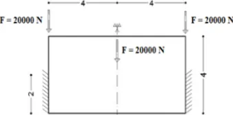
The structure taken here is an 8m X 4m rectangular domain. The rectangular domain is subjected to four point loads of magnitude 20,000 N. Two point loads are applied at end points of upper side and other two point loads are applied at middle point of upper and lower side. The left and right side of rectangular domain are fully constrained. Orthotropic material taken is Carbon Fibre IM7 having volume fraction of 40%. Isotropic material taken is Steel having E of 200GPa and ν of .3 and volume fraction is 40%.
Fig. 1 Design domain of fixed beam subjected to load at four points
B. Problem2. Fixed Beam Subjected To Load At Three Points
Technology (IJRASET)
©IJRASET 2015: All Rights are Reserved
603
20,000 N. Two point loads are applied at end points of upper side and third point load is applied at middle point of upper side. The lower half of left and right side of rectangular domain are fully constrained. Orthotropic material taken is Carbon Fibre IM7 having volume fraction of 40%. Isotropic material taken is Steel having E of 200GPa and ν of .3 and volume fraction is 40%.
Fig. 2 Design domain of fixed beam subjected to load at three points
C. Problem3.Fixed Beam Subjected To Pressure Load At Upper Side
The structure taken here is an 8m X 4m rectangular domain. The rectangular domain is subjected to pressure load of magnitude 2MPa. The two end points of the bottom side are fully constrained.Orthotropic material taken is Carbon Fibre IM7 having volume fraction of 40%.
[image:5.612.229.398.143.227.2]Isotropic material taken is Steel having E of 200GPa and ν of .3 and volume fraction is 40%.
Fig. 3 Design domain of fixed beam subjected to pressure load at upper side
V. RESULTS AND DISCUSSION
A. Fixed Beam Subjected To Load At Four Points
Figure 4 shows topologically optimized shape obtained by Optimality Criteria Method (applied through ANSYS) for orthotropic and isotropic material. In fig. 4 red arrows show externally applied loads and blue colour shows constrained sides.
(a) Initial structure (b) Optimized shape for orthotropic material (c) Optimized shape isotropic material Fig. 4 Difference in optimized shape for orthotropic and isotropic material
[image:5.612.91.547.508.669.2]Technology (IJRASET)
TABLE IICOMPARISON OF PARAMETERS OBTAINED FOR ISOTROPIC AND ORTHOTROPIC MATERIAL
Material Type Isotropic Orthotropic
Compliance(Nm) 0.0448 0.0341
Iterations 29 37
Maximum X direction Stress (MPa) 0.223 0.191
Maximum Y direction Stress (MPa) 0.383 0.0282
Maximum XY direction Stress (MPa) 0.0699 0.0166
Maximum von Mises Stress(MPa) 0.3335 0.1787
Maximum Deflection(mm) 0.00126 0.000948
B. Fixed Beam Subjected To Load At Three Points
Figure 5 shows topologically optimized shape obtained by Optimality Criteria Method (applied through ANSYS) for orthotropic and isotropic material. In fig. 5 red arrows show externally applied loads and blue colour shows constrained sides.
(a) Initial structure (b) Optimized shape for orthotropic material (c) Optimized shape isotropic material Fig. 5 Difference in optimized shape for orthotropic and isotropic material
Optimized shape obtained for orthotropic and isotropic material very nearly same except for few minor or negligible differences. The minor difference is that for optimized shape obtained for orthotropic material the two trusses like bars are connected with left and right sides by thin branches whereas in case of isotropic material there are thick branches.
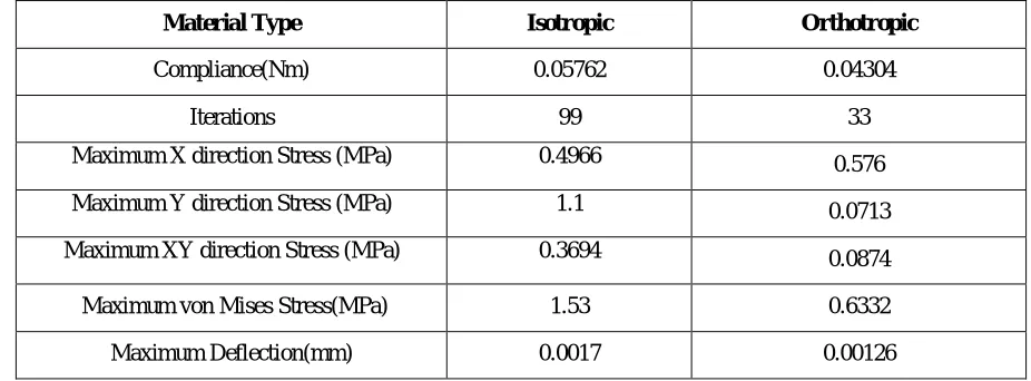
TABLE III
COMPARISON OF PARAMETERS OBTAINED FOR ISOTROPIC AND ORTHOTROPIC MATERIAL
Material Type Isotropic Orthotropic
Compliance(Nm) 0.05762 0.04304
Iterations 99 33
Maximum X direction Stress (MPa) 0.4966 0.576
Maximum Y direction Stress (MPa) 1.1 0.0713
Maximum XY direction Stress (MPa) 0.3694 0.0874
Maximum von Mises Stress(MPa) 1.53 0.6332
[image:6.612.65.554.365.466.2] [image:6.612.72.535.545.716.2]Technology (IJRASET)
©IJRASET 2015: All Rights are Reserved
605
C. Fixed Beam Subjected To Pressure Load At Upper Side
Figure 6 shows topologically optimized shape obtained by Optimality Criteria Method (applied through ANSYS) for orthotropic and isotropic material. In fig. 6 red arrows show externally applied pressure load and blue colour shows constrained points.
(a) Initial structure (b) Optimized shape for orthotropic material (c) Optimized shape isotropic material Fig. 6 Difference in optimized shape for orthotropic and isotropic material
[image:7.612.64.548.160.262.2]Optimized shape obtained for orthotropic and isotropic material is almost same. For both the cases that is for orthotropic and isotropic material a bridge type structure is obtained after topology optimization of initial design domain. There are more arrows acting on upper side of optimized shape obtained for orthotropic material as compared to isotropic material. This is attributed to the fact that, there is more material on upper side of optimized shape (orthotropic material) on which pressure load act while optimized shape (in case of isotropic material) has less material on upper side on which pressure load act.
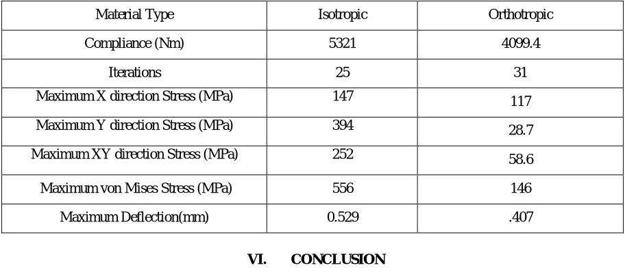
TABLE IV
COMPARISON OF PARAMETERS OBTAINED FOR ISOTROPIC AND ORTHOTROPIC MATERIAL
Material Type Isotropic Orthotropic
Compliance (Nm) 5321 4099.4
Iterations 25 31
Maximum X direction Stress (MPa) 147 117
Maximum Y direction Stress (MPa) 394 28.7
Maximum XY direction Stress (MPa) 252 58.6
Maximum von Mises Stress (MPa) 556 146
Maximum Deflection(mm) 0.529 .407
VI. CONCLUSION
[image:7.612.78.534.420.619.2]Technology (IJRASET)
compared to isotropic material. The value of maximum stress induced in x-direction for orthotropic material is almost comparable with value of maximum x-direction stress induced in case of isotropic material. The maximum y-direction stress, shear stress and von Mises stress induced in orthotropic material are far less than the values of stress induced in isotropic material.
REFERENCES
[1] J. Luo, H.C. Gea, “A systematic topology optimization approach for optimal stiffener design”, Structural Optimization 16, 280-288, Springer -Verlag 1998.
[2] J. Luo, H.C. Gea, “Optimal orientation of orthotropic materials using an energy based method”, Structural Optimization 15, 230-236, Springer -Verlag 1998.
[3] M.P. Bendsoe, O. Sigmund, “Material interpolation schemes in topology optimization”, Archive of Applied Mechanics 69 (1999) 635-654, Springer-Verlag
1999.
[4] O Sigmund, S Torquato, “Design of smart composite materials using topology optimization”, Smart Mater. Struct. 8 (1999) 365–379.
[5] Matteo Bruggi and Paolo Venini, “Topology optimization of incompressible media using mixed finite elements” Comput. Methods Appl Mech. Engrg. 196
(2007) 3151–3164.
[6] Ekrem Buyukkaya, Muhammet Cerit, “Thermal analysis of a ceramic coating diesel engine piston using 3-D finite element method”, Surface & Coatings Technology 202 (2007) 398–402.
[7] S. Banerjee, B.V. Sankar, Chapter on “Mechanical properties of hybrid composites using finite element method based micromechanics”.
[8] Hui Zhang, Xiong Zhang, Shutian Liu, “A new boundary search scheme for topology optimization of continuum structures with design-dependent loads”,
Struct Multidisc Optim (2008) 37:121–129.
[9] Zhao Qun, Ding Yunliang, Jin Haibo, “A layout optimization method of composite wing structures based on carrying efficiency criterion”, Chinese Journal of
Aeronautics 24 (2011) 425-433.
[10] Dheeraj Gunwant, Anadi Misra, "Topology optimization of continuum structures using optimality of criterion approach in Ansys." Int. J. Adv. Eng. Technol 5,
no. 1 (2012): 470-485.
[11] Matteo Bruggi, Gabriele Milani, Alberto Taliercio, “Design of the optimal fiber-reinforcement for masonry structures via topology optimization”,International
Journal of Solids and Structures 50 (2013) 2087–2106.
[12] Tong Xinxing, Ge Wenjie, Sun Chao, Liu Xiaoyong, “Topology optimization of compliant adaptive wing leading edge with composite materials”, Chinese