Sharpness-Based Segmentation of Defocus Blur
SK. Ismael1, J. Ravindranadh2 1
Department of Electronics and communication (ECE), 2Associate Professor R.V.R&J.C. College of Engineering, GUNTUR, Andhra Pradesh (522 019), India
Abstract: The defocus blur is occur when using optical imaging systems, it can either enhance or inhibit our visual perception of the image scene. For tasks such as image restoration and object recognition one might want to segment partially blurred and non blurred image regions. I propose asharpness metric based on lbp and robust segmentation algorithm to separate in- and out -of-focus image regions .using this metric together with image mating and multi scale interference obtain high-quality sharpness maps.
Key words: Local binary patterns, blur, segmentation, defocus, image restoration, object recognition, out of focus blurred.
I. INTRODUCTION
In digital photography, defocus blur is employed to blur background and pop out the main subject using large aperture lenses. Most current image de-blurring methods assume that the blur is spatially invariant [2,3].
The purpose of segmentation of defocus blur is to separate blurred and non blurred regions so that any aforementioned post-processing can be facilitated .this problem is explicitly addressed without quantifying the extent of blurriness and a new sharpness metric based on local binary patterns is introduced.
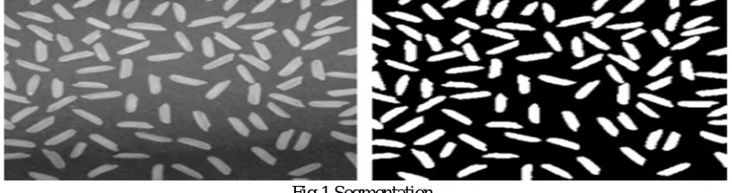
[image:2.612.103.511.465.573.2]The total image can be divide into eight parts each part have some sharp value and blur regions Image segmentation is the process of partitioning a digital image into multiple sections. The goal of segmentation is to simplify and/or change the representation of an image into something that is more important and easier to examine. Image segmentation is typically used to locate objects and background in images. More exactly, image segmentation is the process of assigning a label to every pixel in an image such that pixels with the same label share certain visual characteristics. Image segmentation is an important signal processing tool that is widely employed in many applications including object detection, object-based coding, object tracking, image retrieval, and clinical organ or tissue identification. Thresholding is to select the threshold value is the basic method of image segmentation. Form a grayscale image, can be used to generate binary images. The idea of this method [5].
Fig.1.Segmentation.
Image restoration is the operation of taking a corrupt/noisy image and estimating the clean, original image.
.
[image:2.612.115.487.591.723.2]II. LOCAL BINARY PATERNS
Local Binary Patterns (LBP) have been successfulfor computer vision problems such as texture
[image:3.612.249.364.151.235.2]Segmentation, face recognition, background subtraction and recognition of 3D textured surfaces. The LBP code of a pixel (xc,yc)is defined as
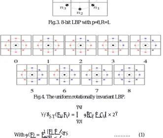
Fig.3. 8-bit LBP with p=8,R=1.
Fig.4. The uniform rotationally invariant LBP.
, ( , ) = − × 2
[image:3.612.145.476.203.484.2]With ( ) = 1 | |≥
0| | < ………. (1)
Where is the intensity of the central pixel ( , ), corresponds to the intensities of the P neighboring pixels located on a
circle of radius R centered at , and TLBP>0 is a small, positive threshold in order to achieve robustness for flat image regions.
Figure 3 shows the locations of the neighboring pixels for P=8 and R=1. In general, the point’s np do not fall in the center of
image pixels, so the intensity of is obtained with bilinear interpolation. A rotation invariant version of LBP can be achieved by
performing the circular bitwise right shift that minimizes the value of the LBP code when it is interpreted as a binary number . In this way, number of unique patterns is reduced to 36. Ojala et al. found that not all rotation invariant patterns sustain rotation equally well [8], and so proposed using only uniform patterns which are a subset of the rotation invariant patterns. A pattern is uniform if the circular sequence of bits contains no more than two transitions from one to zero, or zero to one. The non-uniform patterns are then all treated as one single pattern. This further reduces the number of unique patterns to 10 (for 8-bit LBP), that is, 9 uniform patterns, and the category of non-uniform patterns. The uniform patterns are shown in Figure 4. In this figure, neighboring pixels are colored blue if their intensity difference from centre pixel is larger than TLBP, and we say that it has been “triggered”, otherwise, the neighbors are colored red
III. PROPOSED METHADOLOGY
Fig.5.Examples for different types of blur: (a) uniform motion blur caused by camera shaking; (b) non-uniform motion blur caused by object movement; (c) defocus blur in the background; (d) spatially varying blur caused by atmospheric turbulence; (e) an image over smoothed by Bilateral filtering; (f ) JPEG compression artifacts.
A. Our proposed sharpness metrics have four steps
1) Multi-scale sharpness map generation: The first step, multi-scale sharpness maps are generated using mlbp. Sharpness are constructed at three scales where scale refers o local patch size.
2) Alpha matting initialization : Alpha mating is the process decomposing an image into foreground and back ground .
( , ) =∝ , ( , ) + 1−∝ , ( , ) … … (2) Where alpha mate, α x, y is the opacity value (x, y) pixel position
f is fore ground b is the back ground.The α-map was solved by minimizing the following cost function as proposed by Levin.
3) Alpha map computation; the alpha map was solved by minimizing the followed coast function as proposed by Levin the main use of cost function is to select the most efficiency method to perform the defocus blur.
(∝) =∝ ∝+ (∝ −∝) (∝ −∝) … … … …. (3)
Where α is the vectorized α-map, ∝= ( , ) is one of the vectorized initialization alpha maps from the previous step, and L
is the matting Laplacian matrix. The first term is the regulation
4) Multi-scale inference; A multi scale graphical model was adopted to make h be final decision term that ensures smoothness, and the second term is the data fitting term that encourages similarity to αˆ.
(ℎ) =∑ ∑ ℎ − ℎ + ∑ ∑ ∑€ ℎ − ℎ +∑ ∑|ℎ − ℎ | ………….(4)
Where ℎ =∝ is the alpha map for scale s at pixel location I that was computed in the previous step , and ℎ is the sharpness to be
inferred .The first term on right hand side is the unary term which is the cost of assigning sharpness value ℎ to pixel i in scale s.
Fig .7.The main steps are shown on the left; the right shows each image generated and its role in the algorithm. The output of the algorithm is h1.
The output of the algorithm is h3 which is the inferred sharpness map at the largest scale. This is a grayscale image, where higher
intensity indicates greater shape
IV. RESULTS
The sharpness based segmentation is the advanced detection of blur to compare other methods.
The output of these result is gray scale image where greater intensity indicate greater sharpness, use simple thresholding , , to produce a segmentation . Fig.8. shows not only sharp region and blur region at the fore ground and back ground it also shows the sharp and blur region at the edges of the Image .
V. CONCLUSION
I have proposed a very effective sharpness metric for defocus blur segmentation, this metric is based on the distribution of uniform LBP patterns in blur and non blur image regions. the direct use of the local raw sharpness measure can achieve comparative results to the stat-of-the-art defocus segmentation method that based on sparse representation, which shows the potential of local based sharpness measures. If combined with real-time matting algorithms, such as GPU implementations of global matting, our method would have significant speed advantage over the other defocus segmentation algorithm
REFERENCES
[1] R. Achanta, S. Hemami, F. Estrada, and S. Susstrunk, “Frequency-tuned salient region detection,” in Proc. IEEE Conf. Comput. Vis. Pattern Recognit. (CVPR), Jun. 2009, pp. 1597–1604
[2] H.-M. Adorf, “Towards HST restoration with a space-variant PSF, cosmic rays and other missing data,” in Proc. Restoration HST Images Spectra-II, vol. 1. 1994, pp. 72–78
[3] T H.-M. Adorf, “Towards HST restoration with a space-variant PSF, cosmic rays and other missing data,” in Proc. Restoration HST Images Spectra-II, vol. 1. 1994, pp. 72–78
[4] Bae and F. Durand, “Defocus magnification,” Comput.Graph. Forum, vol. 26, no. 3, pp. 571–579,
[5] K. Bahrami, A. C. Kot, and J. Fan, “A novel approach for partia blur detection and segmentation,” in Proc. IEEE Int. Conf. Multimedi Expo (ICME), Jul. 2013, pp. 1–6
[6] J. Bardsley, S. Jefferies, J. Nagy, and R. Plemmons, “A computational method for the restoration of images with an unknown, spatially-varying blur,” Opt. Exp., vol. 14, no. 5, pp. 1767–1782, 2006. YI AND ERAMIAN: LBP-BASED SEGMENTATION OF DEFOCUS BLUR 199
[7] A. Buades, B. Coll, and J.-M. Morel, “A non-local algorithm for imag denoising,” in Proc. IEEE Comput. Soc. Conf. Comput. Vis. Pattern Recognit. (CVPR), vol. 2. Jun. 2005, pp. 60–65