Technology (IJRASET)
Analysis and Comparative Study of Theoretical and
Practical Air Breakdown Voltages between Spherical
Electrodes
Ms. A. Maanasa Devi1, Ms. D. Revathi2
Electrical and Electronics Engineering, Vardhaman College of Engineering
Abstract— Growth in power sector of nation is a challenge for power engineers for the protection of sensitive power equipments
and their reliable operation. The major challenges in high voltage (HV) power equipments include the quality and reliability of insulators used in power equipments. The HV power equipments are generally subjected to over voltage which may be caused due to thunder bolts or switching actions. These internal and external causes of over voltages determine the safe clearance requirements of proper insulation level. Normally air is the widely used medium as an insulator in different electrical power equipments as its breakdown strength is 30kV/cm. Therefore electrical breakdown characteristic of small air gap under the different applied voltages has its great significance for the design consideration of various air insulated HV equipment. In this paper, theoretical Breakdown Voltages (BDV) of different air gaps between spherical electrodes is compared to the practical values at normal temperature and pressure.
Keywords: High Voltage, Insulators, BDV, Spherical Electrodes
I. INTRODUCTION
To avoid the problems like over voltages and insulator poor quality in high voltage power equipments sphere gap method is considered as one of the standard methods for the measurement of peak value of AC and impulse voltages. This method is used for measuring breakdown voltage of insulating materials and chooses which material has more breakdown strength. The sphere gap method is less complicated and accurate enough. Air has been considered as the insulating medium between two spheres each of radius 5cm.
II. SPHERE-SPHEREELECTRODEARRANGEMENT
[image:2.612.190.440.554.693.2]Technology (IJRASET)
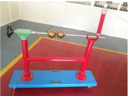
In this arrangement one sphere will be connected directly to earth. Low ohmic shunts like water resistance have to be connected between the sphere and earth in order to control heavy currents due to high voltage. The surfaces of spheres shall be cleaned and dried but need not be polished. In normal use the surfaces of spheres become roughened and pitted. The surface should be rubbed with fine abrasive paper and the resulting dust removed with lint-free cloth any trace of oil or grease should be removed with a solvent. Moisture may condense on the surface of the sparking points in conditions of high relative humidity causing measurements to become erratic. So the spheres are made with their surfaces are smooth and their curvatures as uniform as possible.
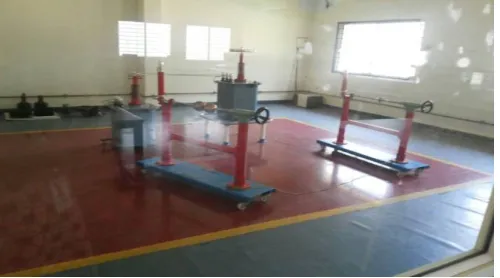
III. PRACTICALARRANGEMENTANDEQUIPMENT
[image:3.612.177.445.217.413.2]For taking readings practically, two transformers each of capacity 50kV are cascaded to give 100kV capacity are taken. Standard spherical Electrodes of 5cm radius, control panel for safe application of voltage and earth rod for discharging the stores charges have been employed.
Fig. 2 Sphere-Sphere Arrangement
[image:3.612.175.448.452.658.2]Technology (IJRASET)
IV. THEORETICALSTUDYOFAIRBREAKDOWNVOLTAGE
Measurement of high voltages and currents is a complex part and the equipments generally have large stray capacitance and large voltage gradient. High voltage equipments are protected against over voltages. The air gap distance between the spheres should not exceed the radius of the sphere. In short duration of time the breakdown voltage can be measured using this method. Sphere electrodes are made with many materials like aluminum, copper etc.
(1)
(2)
V.COMPARISONOFTHEORETICALANDPRACTICALBDVSANDELECTRICFIELDS
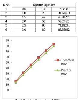
In the table given below the gap between the spherical electrodes varies in the range from 0.5 cm to 3.0 cm and the corresponding breakdown voltage varied from 14 kV to 80 kV. It is also observed that the increase of sphere gap the air breakdown voltage is also increased. Earth rod is used before taking every reading for safety purpose and to earth the stored charges. The difference between theoretical and practical BDVs ranges from 2 to 4kV.
TABLEI
COMPARISON OF PRACTICAL AND THEORETICAL BDVS
S.No 1
Sphere Gap in cm
[image:4.612.180.439.337.669.2]0.5 14 16.33357 2 1.0 28 31.61459 3 1.5 42 45.91291 4 2.0 55 59.29481 5 2.5 68 71.82294 6 3.0 80 83.55632
Fig. 4 Graphical Comparison of BDVs
Technology (IJRASET)
and mediums.
VII.ACKNOWLEDGMENT
The heading of the Acknowledgment section and the References section must not be numbered.Causal Productions wishes to acknowledge Michael Shell and other contributors for developing and maintaining the IEEE LaTeX style files which have been used in the preparation of this template. To see the list of contributors, please refer to the top of file IEEETran.cls in the IEEE LaTeX distribution.
REFERENCES
[1] S. Pillai and R. Hackam, “Electric field and potential distributions for unequal spheres using symmetric and asymmetric applied voltages”, IEEE Transactions on Electrical Insulation, Vol. EI-18, No.5, October 1983.
[2] E. Kuffel, W. S. Zeangle & J. Kuffel, „High Voltage Engineering Fundamentals’, published by Butterworth-Heinemann 2nd edition, 2000.
[3] N. K. Kishore, G. S. Punekar, H. S. Y. Shastry, “Spark over in sphere gaps with alternating voltages and perturbed electric fields”, annual report conference on „Electrical Insulation and Dielectric Phenomena‟, 2009.
[4] M. S. Naidu and V. Kamaraju, „High Voltage Engineering’, published by Tata McGraw-Hill 3rd edition, 2004.
[5] Y. Nishikori, S. Kojima, and T. Kouno, “A study of the field utilization factor and the maximum electric field at spark over of the standard sphere gaps”, Translated from Denki Gakkai Ronbunshi, Vol.21-B, No.3, March 2001.