5
X
October 2017
International Journal for Research in Applied Science & Engineering Technology (IJRASET)
ISSN: 2321-9653; IC Value: 45.98; SJ Impact Factor:6.887 Volume 5 Issue X, October 2017- Available at www.ijraset.com
Compact Multiband Rectangular Microstrip Patch
Antenna for S, C, And X Band
Anjali1, Neha Garg2 1, 2
Department of Electronics and Communication, Ajay Kumar Garg Engineering College, Ghaziabad
Abstract: This paper introduces the novel depiction of rectangular microstrip patch antenna on an affordable FR4 substrate of dielectric constant 4.4 and loss tangent 0.02. Ithas dimension of 40mmX 40 mm X 1.6 mm. The proposed multiband microstrip patch antenna can resonate at 2.55 GHz, 3.96 GHz, 5.38 GHz, 6.37 GHz, 7.78 GHz, 9.34 GHz, 10.89 GHz, 11.60 GHz, 12.17 GHz and 14.43 GHz. To achieve multiband frequency, three rectangular slots have been cut on the patch. The procured bandwidth is satisfactory and voltage standing wave ratio (VSWR) is less than 1.5. The execution of multiband antenna is simulated and attested by estimation. On the contrary, the proficiency of proposed multiband patch antenna has been justified through surface current distribution and efficiency of measured result.
Keywords: microstrip patch antenna, multiband, gain, U-Slot patch, bandwidth
I. INTRODUCTION
Recent advancement in wireless communication have proliferated the requirement of antenna with compact size and low cost, that can work at various frequencies with enough bandwidth. Microstrip patch antenna has benefit of low profile, light weight, and affordable cost. There are numerous and well known methods to increase the bandwidth of antennas, including increase of thickness, the use of low dielectric substrate, slotted patch antenna, the use of various impedance matching and feeding techniques, and the use of multiple resonators[1]. The design of multi-band antennas was the subject of several research studies [2],[3]. The technology insertion slots is used [4],[5],[6]. In [7], a dual band antenna for GSM1800/1900/ UMTS/ LTE/UWB. In [8], a triple band single slotted microstrip patch antenna is presentedfor WLAN and WiMAX application. In [9], the authors propose a microstrip patch antenna for LTE. In [10] design of planar monopole antenna is designed using L and U shaped slot for WLAN/WiMAX Applications. Microstrip patch antenna had been designed for S and X band [11], [12]. This paper presents microstrip patch antenna with three slots on patch and two symmetrical U-shaped slots for multiband at 1 GHz. The design employs
50 Ω microstrip line feeding and simulated using High Frequency Structure Simulator (HFSS). The proposed design can achieve the
reflected power is less than −16 dB for all resonant frequencies. The VSWR is lies between 1 and 2 and very good gain is obtained.
II. ANTENNA DESIGN
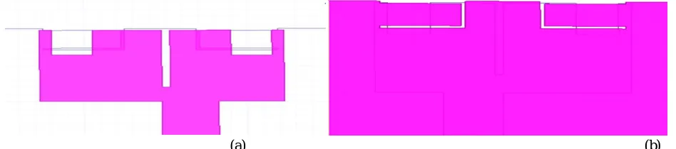
The structure of proposed multiband microstrip patch antenna is shown in Fig. 1 (a) and (b), which is designed on FR4 with dielectric constant of 4.4 and loss tangent of 0.02. The total volume of the proposed antenna is about 40×40×1.6 mm3 and it resonates for 2.55 GHz, 3.96 GHz, 5.38 GHz, 6.37 GHz, 7.78 GHz, 9.34 GHz, 10.89 GHz, 11.60 GHz, 12.17 GHz, and 14.43 GHz . The dimension of the proposed microstrip patch antenna top view is displayed in Table I and back side view is shown in Table II. The top and back side view of proposed design is shown in Fig. 2(a) and (b), respectively.
Several methods are available in the literature to feed the signal source, in which insert fed technique is easier for fabrication. To achieve the multiband operation, a slot can be inserted in a ground plane with a dimension of 40×30.5 mm2. In order to obtain the lower return losses
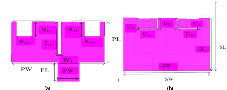
[image:2.612.49.523.609.714.2](a) (b)
Fig 2 Dimension of proposed microstrip patch antenna: (a) top side view (b) back side view.
Table I Parameter of top side view of antenna
PARAMETERS VALUES(mm)
Patch length(PL) 20
Patch Width(PW) 30
Feed Length(FL) 10
Feed Width(FW) 7
Slot(S11) 7
Slot(S12) 5
Slot(S21) 7
Slot(S22) 5
Slot(L1) 16
Slot(W1) 1
Table IIParameter of Back view
III. SIMULATION RESULT
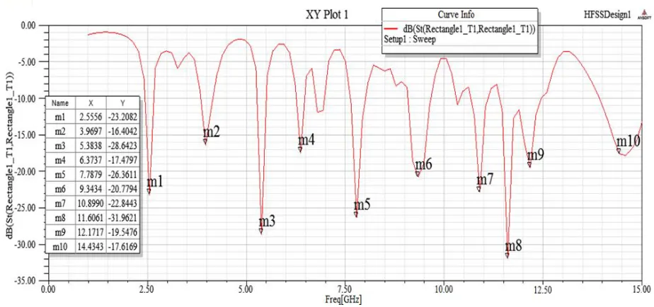
The simulation results are carried out to test the performance of proposed microstrip patch antenna. The simulation results of reflected power and VSWR of the proposed microstrip patch antenna are shown in Fig. 3.This microstrip patch antenna simultaneously resonates for the frequency 2.55 GHz, 3.96 GHz, 5.38 GHz, 6.37 GHz, 7.78 GHz It can be seen from Fig. 3, a very low return loss of -31.96 can be achieved at the frequency of 11.60 GHz. The outcome of simulated results of return loss confirms the good performance for proposed design of multiband patch antenna.
Parameter VALUE
Ground Length(GL) 30.5
Ground Width(GW) 40
Substrate Length(SL) 40
Substrate Width(SW) 40
U11 10
U12 10
U13 0.5
International Journal for Research in Applied Science & Engineering Technology (IJRASET)
[image:4.612.76.538.71.288.2]ISSN: 2321-9653; IC Value: 45.98; SJ Impact Factor:6.887 Volume 5 Issue X, October 2017- Available at www.ijraset.com
Fig. 3 Simulated results of proposed patch antenna for Return loss
[image:4.612.77.535.524.685.2]Fig. 4 shows the gain for various frequencies. It can be seen from Fig. 4, 8.3 dB is the maximum gain obtained at -12.1 GHz.
Fig 4 Simulted result of proposed patch antenna for Gain
Under various resonant frequencies, the performances of return loss and gain displayed in Table III. Table IIIReturn loss and Gain at various frequency
Resonance Frequency Return Loss Gain
2.55 -23.20 Below 0
3.96 -16.40 0.30
5.38 -28.64 Below 0
6.37 -17.47 Below 0
7.78 -26.36 1.3
9.34 -20.77 0.81
10.89 -22.84 3.1
11.60 -31.96 5.07
12.17 -19.54 8.3
14.43 -17.61 3.7
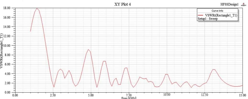
The performance of VSWR for the proposed microstrip patch antenna is shown in Fig. 5, which lies between 1 and 2 for all resonant
Fig 5 Simulated VSWR of proposed antenna
Table IV VSWR at various frequency.
Resonance Frequency VSWR
2.55 1.31
3.96 1.41
5.38 1.11
6.37 1.36
7.78 1.11
9.34 1.16
10.89 1.16
11.60 1.15
12.17 1.26
14.43 1.41
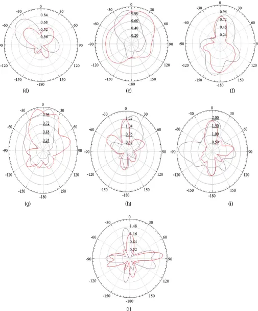
Fig. 6 shows the radiation pattern for the microstrip patch antenna, (a).2.55 GHz, (b).3.96 GHz, (c). 5.38 GHz, (d). 6.37 GHz, (e). 7.78 GHz, (f). 9.34 GHz, (g). 10.89 GHz, (h) 11.60 GHz, (i) 12.17 GHz, and (j) 14.43 GHz. Omni directional radiation pattern is obtained for 11.60 GHz, 12.17 GHz and 14.43 GHz resonant frequencies. Bi-directional radiation pattern is obtained for 5.38 GHz, 6.37 GHz and 9.34 GHz resonant frequencies. Directional radiation pattern is obtained for 2.55 GHz, 3.96 GHz, 7.78 GHz and 10.89 GHz resonant frequencies.
[image:5.612.72.547.578.720.2]International Journal for Research in Applied Science & Engineering Technology (IJRASET)
ISSN: 2321-9653; IC Value: 45.98; SJ Impact Factor:6.887 Volume 5 Issue X, October 2017- Available at www.ijraset.com
(d) (e) (f)
(g) (h) (i)
[image:6.612.54.559.74.682.2](j)
(a) (b)
(c)
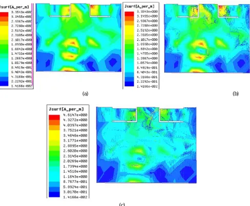
Fig 7 Surface current distribution on the microstrip patch antenna, (a) 11.60 GHz, (b) 5.38 GHz, (c) 7.78 GHz.
IV. CONCLUSION
In this paper, a design of multiband microstrip patch antenna is proposed, which covers the frequency range between 2 GHz and 14 GHz. The return loss for all resonant frequency is less than −16 dB and also the proposed design achieves Omni directional and bi-directional radiation pattern. The obtained peak gain is greater than 5 dB and the simulation results of proposed antenna provide the better outcome for S, C and X band frequency applications.
REFERENCES
[1] K. He, S. Gong, and F. Gao, 2015 “Low-profile wideband unidirectional patch antenna with improved feed structure,” Electron. Lett, pp 317–319.
[2] Z.H. Li, Y.L. Xue, Z.Q. Deng, (2009) “Study on optical switching effect of photonic crystals with negative effective index of refraction,” Optik pp. 605–609. [3] Zhao Wanga, Eng Gee Lima, and Xiaodong Chenb, 2011 “Study the Ground Plane Effect of a Multiband Antenna for Multiple Wireless Communication
System,” Advanced in Control Engineeringand Information Science, pp.2521-2526.
[4] Nivedita Girase, Rahul Tiwari, Archana Sharma, and Hema Singh, 2014 “Design and Simulation of Slotted Rectangular Microstrip Patch Antenna,” International Journal of Computer Applications, vol. 103, no. 17, pp. 19-23.
[5] J.W. Kim, T.H. Jung, H.K. Ryu, J.M. Woo, C.S. Eun, and D.K. Lee, 2013 “Compact multiband microstrip antenna using inverted-L- and T-Shaped parasitic elements,” IEEE Antennas Wirel. Propag. Lett.
[image:7.612.68.556.88.491.2]International Journal for Research in Applied Science & Engineering Technology (IJRASET)
ISSN: 2321-9653; IC Value: 45.98; SJ Impact Factor:6.887 Volume 5 Issue X, October 2017- Available at www.ijraset.com
[7] Aravind S, Saira Joseph, Mridula S, Binu Paul, and P Mohan, 2015“Compact Dual Band Antenna for GSM1800/1900/ UMTS/ LTE/UWB,” International Conference on Information and Communication Technologies, pp. 1349-1356.
[8] Gehan Sami, Mahmoud Mohanna, and Mohamed L. Rabeh, 2013 “Tri-band microstrip antenna design for wireless communication applications,” National Research Institute of Astronomy and Geophysics, pp. 39-44.
[9] Mayuri. M. Dekate, 2013 “Design Simulation and Fabrication of Microstrip Patch Antenna,” Advance in Electronic and Electric Engineering, vol. 3, no 3, pp. 347-354.
[10] Mahdi Moosazadeh and Sergey Kharkovsky, 2014 “Compact and Small Planar Monopole Antenna With Symmetrical L- and U-Shaped Slots for WLAN/WiMAX Applications,”IEEE Antennas And Wireless Propagation Letters, vol. 13, pp. 388-391.
[11] P. A. Ambresh, P. M. Hadalgi and P. V. Hunagun, 2011 “Compact omnidirectional patch antenna for s band frequency spectre,” International Journal of Advances in Engineering & Technology, vol. 1, issue 4, pp. 155-159.