Modelling and Performance Evaluation of
Square Wave And Spwm Based Inverter Fed
AC Drive
Garima Solanki#1, Chandan Gurjar#2, Mahesh Lokhande#3 Electrical & Electronics Engineering Department, RGPV, Bhopal(M.P.)
Abstract- The controlling of AC motor is handled by a AC drive. This paper is versatile and standalone system and most of the facilities to interface with PC is implemented. The paper involves the speed control of three phase induction motor by using the six step(180˚ conduction) and PWM fed VSI. Here is used comparison and analysis of six step(180˚ conduction) and PWM fed VSI based drive. PWM is most reliable and efficient way to regulate the output voltage of VSI. This technique minimizes the lower order harmonics and improves the response of VSI.
Keywords—AC Drive, SPWM, VSI, MATLAB/SIMULINK
I. INTRODUCTION
Drive plays an important role in industries. Main function of drive is to control flow of energy from the mains to process. Energy is supplied through the motor shaft. Drive is defined as
“It is an electromechanical energy conversion device to convert
electrical energy into mechanical energy to impart motion for machines and mechanisms for various kinds of process control. Various applications in industries required variable speed drive or variable torque drive should be able to perform these operations efficiently. The state of the motor shaft describe by two physical quantities torque and speed. To control the flow of energy we must control these quantities in practices on of them
is controlled and we speak of “torque control” or “speed control”. The load determines the speed when operated in torque
control mode. Likewise when operated in speed control the torque is determined by load. There are basically two types of drives are used in industries
D. C. Drive.
A. C. Drive.
The AC motor drives are widely used in industrial and process applications where high performances are mandatory. At present, induction motor has many advantages over the rest of motors. The main advantage is that the induction motor does
not require an electrical connection between stationary and rotating parts of the motor. Therefore, they do not need any mechanical commutator (brushes), leading to the fact that they are maintenance free motors. Induction motors also have low weight and inertia, high efficiency and high over load capability. Therefore, they are cheaper and more robust and less proves to any failure at high speeds. Furthermore, the motor can work in explosive environments because of the absence of spark.
The main power components of an AC drive have to be able to supply the required level of current and voltage in a form the motor can use. The controls have to be able to provide the user with necessary adjustments such as minimum and maximum speed settings, so that the drive can be adapted to the user's process. Spare parts have to be available and the repair manual has to be readable. It's nice if the drive can shut itself down when detecting either an internal or an external problem. It's also nice if the drive components are all packaged in a single enclosure to aid in installation but that's about it. The paradox facing drive manufacturers today is that as they make their drives easier to use, the amount of training with which they must provide their users increases. This is because as drives become easier to use they are purchased more and more by people of less and less technical capability.
demand in the motor drive study. This high-level 4th generation programming language and interactive environment enables users to perform intensive calculation-based tasks very fast. The toolbox allows matrix manipulation, functions and data plotting, algorithm implementation, creation of the user interfaces, and interfacing with programs in other languages. It has been widely adopted for over 25 years in the academic community, industry and research centers. The toolkit provides the users with a large collection of toolboxes and modules for a variety of applications in many fields of interest. Its interactive graphical superstructure Simulink was added to Matlab to make the modeling and simulation of various systems as easy as connecting predefined and designed building blocks. Simulink contains many block sets that are used in different applications, such as the communication block, signal-processing block, etc.
II. THREE PHASE DRIVE SYSTEM
Three phase induction motors are more common employed in adjustable speed drives than three phase synchronous motor. When a three phase supply is connected to three phase stator winding, the speed of this rotating field, called synchronous
speed is given by
s
N
=rpm
P
f
120
or
n
s=rps
P
f
2
…… (1) AlsoP
f
1 12
P
4
………(2) Wheref = Supply Frequency in Hz.
ω1= Supply Frequency in rad/s
P = No. of stator poles.
Rotor can not attain synchronous speed. It must run at a speed Nrless than Ns,
Where
s
N
N
r
s1
……… (3)
s
s m
1
………(4)Where
Nr =Rotor Speed in rpm ωm= Rotor speed in rad/s
s = slip =
s m s s r s
N
N
N
…….(5)Three Phase Induction Motors are admirably suited to fulfill the demand of loads requiring substantially a constant speed. Several applications however, need adjustable speeds for their efficient operation.
The various methods of speed control are as follows.
1. Stator Voltage Control
2. Frequency Control
3. Constant V/f Control
4. Vector Control
5. Changing the stator poles
The tested motor has the following characteristics: rated power 3 HP, voltage 420 V, current 11 A, speed 1480 r/min, torque 11.9 Nm, and the moment of inertia 0.038 kgm2.
III. SIX-STEP BASED INVERTER FED AC DRIVE MODEL
Fig. 1. Six step switching model
Fig.2. Complete Drive model in MATLAB
A) Simulation Results
The squirrel cage induction motor chosen for the simulation studies has the following parameters: 3 HP, 420 V, 50 Hz
Rs=0.453 ohm Rr=0.816 ohm L s=0.022 H Lm=0.63 H
L r=0.022 H J=0.089 kg m2, P=4
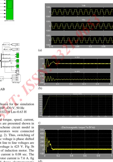
The simulation results for developed torque, speed, current, voltage and speed-torque characteristics are presented shown in fig.3. Fig.1 shows six step switching scheme circuit model in Matlab. This six Simulink pulse generators were connected directly to the IGBT based inverter (Fig. 2). Thus, switching of the three inverter legs supplied by the dc voltage is phase shifted
by 180° conduction. The inverter output line to line voltages are shown in fig. 3a. The r.m.s. value of voltage is 425 V. Fig 3b shows stator current and rotor current of induction motor. The settle point of stator current and rotor current is 0.08 sec. The value of stator current is 10.47 A and rotor current is 7.6 A. fig 3c shows speed 1485 rpm and fig. 3d shows electromagnetic
torque 15.11 NM. The all output shows harmonics are presented.
(a)
(b)
©
Fig.3. a) Inverter output line to line voltage, b) motor stator & rotor current,
c) Speed in rpm d) Torque in NM
IV. SPWM for Three Phase VSI Fed AC Drive Model
This is an extension of the one introduced for single-phase VSIs. In this case and in order to produce 120⁰ out-of-phase load voltages, three modulating signals that are 120⁰ out of phase are used. Fig. 5a shows the ideal waveforms of three-phase VSI SPWM. A model developed to simulate the PWM controller is presented in Fig. 4. It includes three sine-wave generators accompanied by speed-amplitude and modulating index reference blocks, a carrier generator, three comparators and gate drivers. In this way, the symmetrical triangle double-sided wave of the carrier frequency is compared with the modulating wave thereby generating the control pulses. The control output represents the chain of constant magnitude pulses, the duration of which is modulated to obtain the sinusoidal waveform. Fig. 2 shows the full-loaded drive running with nominal speed.
Fig. 4 SPWM switching scheme
(a)
(b)
[image:5.612.180.567.112.623.2](d)
Fig. 5 a) output line to line inverter voltage, b) Motor stator & rotor current, c) Speed in rpm d) Torque in NM (ma=0.8,mf=9)
A) Simulation Results
In fig.5a shows the elimination of lower order harmonic the output voltage becomes smooth (behaves like sine wave). The rotor current fluctuates between 0 to 0.1 sec and after 0.1 sec its magnitude becomes 6.4 amps. It can easily observe by using the PWM fed inverter; the starting current value goes to minimize. The r.m.s. value of voltage is 420 V. Fig 5b shows stator current and rotor current of induction motor. The settle point of stator current and rotor current is 0.1 sec. The value rms value of stator current is 9.3 A and rotor current is 6.4 A. Fig 5c electromagnetic torque 11.78 NM. Fig.5d shows speed 1459 rpm. The speed is constant as compare to square wave fed drive.
V. CONCLUSION
The modeling, analysis and control of 3-Φ induction motor with performance analysis of square wave based VSI fed 3- Φ Induction Motor drive and PWM fed VSI AC Motor drive. The two test results are implemented VSI fed and PWM fed asynchronous motor drive is shown. Control process of machine can be improved by PWM inverter. The Rotor current, stator current and electromagnetic torque is reduced by using PWM inverter in induction machine and speed will also be reduced in motoring mode. The harmonics content of PWM fed VSI drive has less as compared to square wave voltage inverter drives. SPWM makes the output voltage of VSI as a function of sine wave and by varying the modulation index it can vary the frequency of output voltage of VSI in such a way that v/f ratio
switching performance of the motor drive converter from the different operation when compared to the six-step modulation and PWM techniques.
REFERENCES
[1] S.K. Pillai, A First Course on Electrical Drives 2nd Edition 2004, New Age International Publication.
[2] M.H. Rashid, Power Electronics Circuits, Drives and Application 3rdEdition 2007 Pearson Prentice Hall.
[3] Y.Hori “Control Theoretical consideration Relating to an Induction
Machines Flux Observer”, IEE Japan Trans. vol, 106-D, no 11, pp
1001-1008.
[4] Bimal K. Bose, Modern Power Electronics and AC Drives, 3rd
impression, India: 2007. Pearson Education, Inc.
[5] Gopal K. Dubey, Fundamentals of Electrical Drives, 2nd edition, 2007,
Narosa publishing house, New Delhi, India.
[6] Bimal K. Bose, “High Performance Control and Estimation in AC
Drives”, IEEE IECON Conf. Rec., pp. 377-385, 1997.
[7] Xiaorong Xie, Qiang Song, Gangui Yan, Wenhua
Liu“MATLAB-based
Simulation of Three-level PWM Inverter-fed Motor Speed Control
System” IEEE 0- 7803-7768-0/03.
[8] Neha Thakur1, Rakesh Singh Lodhi2 “Computer Simulation of
SPWM-VSI for Minimizing the starting torque and current in Asynchronous
Motor Drive”International Journal of Research (IJR) Vol -1, Issue-5,
June 2014 ISSN 2348-6848
[9] M. G. Ioannides “Design and Implementation of PLC based Monitoring
Control System for Induction Motor” IEEE conference vol.3,sep. 2004.
[10] P.C. Krause, O.Wasynezuk, S.D. Sudhoff, “Analysis of Electric
[image:6.612.38.288.116.234.2]