m
jjiiispWff?!
PIS«*?
1'
EUROPEAN ATOMIC ENERGY COMMUNITY - EURATOM
ÄSE'
i-ii/ííl
¡^r-íte- ·;:<
faß
li
Baili
'Ü
wífcft·»!
£ΐ!Π;ΐΙί,Μ1Ι(Ι·»>1«ι· 'il.
:if,%lä,ihrtr>tfrii£j»«'
KlM
m
hew
h&'X Φ'-lP.lÀ5SAN
ANALOG MODEL AND A DIGITAL O
CONTAINMENT STUDIES
• *;'ìV
FOR
W.
f«
UDIES
iîW
»••Α G. GAGGERO (EURATOM)
P.M. GERINI and G. LEONI (CISE)
IMI
Κii·?
Ä
¡-to]
I
ίίίιϋϊί
Ilt
ij
;Í{jf¡»{íi "»yi
\ã&m
Ί Wftfltjl
■Ï ¡Ï ;
HW»«
m
mw.
Joint Nuclear Research Center Ispra Establishment - Italy
¡Γ*;1»
yjii
η
SS?
This d o c u m e n t wee prepared u n d e r t h e sponsorship of t h e Commission of t h e E u r o p e a n Communities.
ι"'/*?1:
ift
Neither t h e Commission of t h e E u r o p e a n Communities, its contractors nor any person acting on their behalf :
oJtfatfHiWCPf
1
K£:|
M a k e any warranty or representation, express or implied, with respect to t h e accuracy, completeness, or usefulness of t h e information contained in this document, or t h a t t h e use of any information, apparatus, m eth o d , or process disclosed in this d o c u m e n t m a y not infringe privately owned rights; or
8ΒΡΦíffl SÄHäffiiiü
H m ·%$^1 Inför
A s s u m e any liabihty with respect to t h e use of, or for damages resulting from t h e use of any information apparatus, m e t h o d or process disclosed m this document.
lili
A mathematical model is presented ror the determination of pressure and temperature transients inside the containment building, following a Ioss-of-coolant accident due to a rupture in the primary cooling system of a nuclear power plant having water as the primary coolant. The model
EUR 3927 e
M A C A C O - PREST : A N A N A L O G M O D E L A N D A DIGITAL C O D E F O R C O N T A I N M E N T STUDIES by G G A G G E R O (Euratom. CETIS), P.M. GERINI and G LEONI (CISE), J.B. van ERP (Euratom) (Euratom, stationed at CISE)
European Atomic Energy Community - E U R A T O M Joint Nuclear Research Center - Ispra Establishment (Italy) Scientific Information Processing Center - CETIS
Brussels, May 1968 - 144 Pages - 7 Figures - FB 175
includes the calculation of the radiation doses incurred to the thyroid due to inhalation of radioactive iodine released outside the containment building as a function of height of release, time of exposure, distance, etc. The model in its present form is limited as regards its application to «dry> containment systems without pressure relief (pressure-suppression systems are, e.g., not covered ).
The mathematical model was first used in conjunction with an analog computer ( M A C A C O = Modello Analogico CAIcolo Conteni-tore), and was subsequently programmed and extended for digital computer use (code : PREST), for more rapid availability as a computation tool for routine evaluations.
includes the calculation of the radiation doses incurred to the thyroid due to inhalation of radioactive iodine released outside the containment building as a function of height of release, time of exposure, distance, etc. The model in its present form is limited as regards its application to «dry» containment systems without pressure relief (pressure-suppression systems are, e.g., not covered ).
MACACO - PREST
AN ANALOG MODEL AND A DIGITAL CODE FOR
CONTAINMENT STUDIES
by
G. GAGGERO (EURATOM) P.M. GERINI and G. LEONI (CISE)
J.B. van ERP (EURATOM)
1 9 6 8
Joint Nuclear Research Center Ispra Establishment - Italy
SUMMARY
A mathematical model is presented for the determination of pressure and temperature transients inside the containment building, following a Ioss-of-coolant accident due to a rupture in the primary cooling system of a nuclear power plant having- water as the primary coolant. The model includes the calculation of the radiation doses incurred to the thyroid due to inhalation of radioactive iodine released outside the containment building as a function of height of release, time of exposure, distance, etc. The model in its present form is limited as regards its application to «dry> containment systems without pressure relief (pressure-suppression systems are, e.g., not covered ).
The mathematical model was first used in conjunction with an analog computer (MACACO = Modello Analogico CAIcolo Conteni-tore), and was subsequently programmed and extended for digital computer use (code : PREST), for more rapid availability as a computation tool for routine evaluations.
KEYWORDS
TRANSIENTS HEAVY WATER COOLANT PRESSURE ANALOG SYSTEMS
TEMPERATURE P-CODES
BUILDINGS COMPUTERS MATHEMATICS FAILURES
THYROID LOSSES RADIATION INJURIES ACCIDENTS
1. INTRODUCTION 5
2. DESCRIPTION OF THE MATHEMATICAL MODEL g
2.1 Principal Assumptions g
2.2 Equations Determining Pressure and Temperature Transients Q
2.3 Equations Determining the Dose Incurred to the Thyroid
by Inhalation of Radioactive Iodine -"-3
3. DESCRIPTION OF THE ANALOG MODEL 17
3.1 General Aspeets 17
3.2 Equations and Simplifying Assumptions for the Analog
Model 18
3.3 Description of the Analog Computer Circuit 21
3.3.1 Further Simplifications Assumed for the Analog Circuit 21
3.3.2 Some Details of the Analog Circuit 22
3.4 Presentation of Some Illustrative Results 23
4. DESCRIPTION OF THE DIGITAL CODE 23
4.1 General Aspects 23
4.2 Structure of the Digital Code 24
4.3 Equations for the Digital Code 25
4.4 Numerical Methods for the Digital Code 2 7
4.4.1 Solution of the Energy Balance 2 7
4.4.2 Solution of the Fourier Equation for Heat Conduction 2 8
4.4.3 Solution of the Equations for Dose Determination 31
4.5 Computer Code Usage 32
4.5.1 Coding Language 32
4.5.2 Input Data Sheets 32
4.5.3 Code Output 42
4.6 Listing of the Source Program 43
4.7 Sample Problem 81
Nomenc lat ure 120
Bibliography 130
List of Figures I3I
Acknowledgements 131
PREFACE
The study contained in the present report is the result of a cooperation between CETIS (Euratom's Computer Center, at Ispra, Italy) and the Safety Evaluation Group of the Nuclear Engineering Department of CISE (Milan) in the area of computer codes relative to safety evaluation.
This cooperation was agreed upon in March 1966 by Prof. M. Silvestri and Dr. G. Pozzi, respectively, of CISE and CETIS.
plants, the authors were first inclined to use the PTH-code (developed by Kaiser Engineers, Oakland, Calif.) £3-3» which was the only computer code freely
available at the time the study was initiated. It turned out, however, that for reasons of numerical stability (in particular regarding heat transferred to or from the internal free volume of the containment building), a limitation was posed in the PTH-code on the adjustability of the time-scale; this result-ed in the use of excessive computer-time for transients lasting as long as 24 hrs.
In order to overcome the above mentioned problem of adjustability of the time-scale, an analog model was developed, which initially was based on a similar approach as the PTH-code. Subsequently new features were added (such as, e.g., the calculation of radiation doses due to iodine inhalation), and in parallel the development of a digital code was undertaken. The latter code (PREST), which was based to a large extent on the analog model, does not have any longer the strong limitation for time-scaling such as encountered in the PTH-code: The typical machine-time for a 24 hrs transient is about 10 minutes (IBM 360/65).
The present report describes both the analog model (including the analog circuit) and the digital code, since in future use, depending on the type of problem to be treated, one or the other may be more convenient. It was shown by means of a number of test problems that results obtained by means of the analog model and those obtained by means of the digital code do not differ significantly.
A brief phenomenological description of the type of accident studied is given in the following:
As a consequence of a rupture in the primary cooling circuit, high enthalpy coolant is released into the free volume of the containment building (blow-down phase), resulting, in general, in a rapid increase of pressure and temperature inside the containment. This blow-down phase is
released to the containment atmosphere. As a result of the increased pressure, and the postulated release of iodine from the core into the free volume of the containment, leakage of radioactive iodine will occur from the containment into the area surrounding the nuclear power plant.
The presence of consequence-limiting engineered safeguards, such as internal and/or external spray systems, and recirculation clean-up systems (provided with filters, possibly also for methyl-iodine) will decrease the pressure (and thus the leakrate) as well as the iodine concentration inside the containment building.
The final goal of the calculation is the determination of the radiation doses incurred to the thyroid by inhalation of iodine, for various heights
of release, at various distances from the containment, under various atmospheric conditions, and for various time periods of exposure.
2. DESCRIPTION OF THE MATHEMATICAL MODEL
2.1 Principal Assumptions
The model is based on the following principal assumptions:
1) Thermodynamic equilibrium prevails, at all instants, for the gaseous and liquid phases in the free volume of the containment building (also during the blow-down phase).
2) The air inside the containment building follows, for the pressure and temperature range of interest, the ideal gas law.
3) The total free volume of the containment building is assumed available at the instant zero of the accident, and remains so for the entire duration of the period studied (all various compartments inside the containment building are assumed to be in complete communication).
If, however, the values of pressure and temperature inside the containment building are predominantly determined by the internal energy of the primary coolant, then the assumption of thermodynamic equilibrium (i.e., one single temperature for liquid and gaseous phase), is justified by the relatively small error introduced, which, moreover, is in many cases negligible if compared with other errors due to uncertainties in the overall computation (e.g. , those
due to uncertainties in heat transfer coefficients, etc.).
Assumption 2) is justified by the small range in which the pressure and temperature of the air change during the type of transients here considered.
Assumption 3) does not, in general,hold true if comparison is made with actual cases encountered. However, it may be observed that in many cases the first group of compartments inside the containment building is arranged immediately around the reactor-core, so that a rupture of the primary cooling circuit will lead first to the pressurization of those compartments, that do not have a wall in common with the outer containment shell. The possibly higher value, reached by the pressure during a transient in such
compartments, will thus not be transferred to the containment shell.
Consequently, assumption 3) is conservative for the type of compartment-arrang-ment as described above, since the maximum value of the pressure felt by
the outer containment shell during the transient will be reduced by the presence of the intermediate compartments.
If, however, the rupture takes place in a compartment having a wall in common with the outer containment shell, it is clear that the pressure transient in this compartment (and thus on the outer containment shell)
8
2.2 Equations Determining Pressure and Temperature Transients
2.2.1 The pressure and temperature transients inside the containment are determined by the energy, mass and volume balances, relative to the free volume inside the containment building.
Energy balance
E+_(t) = E° + E, ,(t) + E (t) + E, (t) + E . ( t ) + Σ E. (t) + Σ Ε. (t) + E .(t)
tot tot bd η dec chem . ι . Ί spi
- M . c .T ( t ) + M . ( t ) . U . ( T ) + M ( t ) . U (T ) = a v , a c w , l 1 c w,g g c
= M . c .T ( t ) + M . ( t ) . U . ( T ) + M ( t ) . Η , ( T ) + V ( t ) . p (T ÌH (T )
-a v , a c w , l 1 c w,g l e Kg c I g c
- Ρ (T ) . V ( t ) s
g c
s M . c .T ( t ) + M . . ( t ) . H . (T ) + V ( t ) . p (T )LH (T ) - Ρ (T ) . V ( t )
a v , a c w , t o t l e g c I g c g e
( 1 )
In eq. (1) (last member), the specific enthalpy (H ) and the specific internal energy (U ) for the liquid phase were assumed equal (the error introduced in this way is negligible).
Mass balance:
M (t) = M° + M ,.(t) + M .(t) (2)
Wjtot w w,bd spi Volume balance:
v ( t )
=
v
° - ργττ) î
M
w,tot
(t)
-
ν ( ΐ )
Λ
(
ν ]
(3)
The energy terms of eq. (1) may be written as follows
E
d e c
( t )θ,
aec
( t ) . d t = Ν
f t
ç ( t ) . d t
E . (t) = E . . . ( l e "t A c h e m)
chem chem,tot
E.(t)
E.(t)
E .(t) spi
ft
■Ό rt
■Ό
Φ±(ΐ).άΐ
Φ.(t).dt
Γ .(t).c .Τ ..dt Tspi S p i P , W S p i
The mass-terms of eq. (2) may be written as follows:
(7)
(8)
(9)
(10)
(11)
»«o ,.o „o o M = M . + V . ρ Wjtot w,l g
M
w,bd
(t)= f
rbd
(t)-
dtM .(t) = I Γ .(t).
w,spiv J spi
dt
(12)
(13)
(14)
The volume terms of eq.(3) do pot require any further clarification. As to the decay heat (eq.7) it may be observed that the data of Shure-Dudziak L3J seem to be considered at present the most accurate.
On the basis of eq.(l), having determined all energy terms, it is possible to find the temperature T (t) of the internal atmosphere of the containment building. Then by means of T (t) one determines the pressure transient :
IO
„ο Τ , (t)
Ρ (
t) =pO._V E^abs
( 1 6 )a a
Τ° , V(t)
c,abs
Ρ
aK„(t) = Ρ (t) + Ρ (t) (17)
c,abs a g
2.2.2 The evaluation of the energy terms E.(t) and E.(t) (referring, respect
ively, to heat exchanged with the internal structures and with various parts
of the outer shell of the containment building), gives usually rise to
most difficulties, especially if the problem is treated by means of a digital
computer. This is caused, amongst others, by the wide range of the physical
properties (p, c , k, etc.) of the materials concerned, as well as the
dimensions and relative positions of the structures, resulting in a very wide
range for the time constants determining the time behaviour of the heat
fluxes in question.
For the sake of simplicity the various structures are, as far as the
transient behaviour of the heat exchanged is concerned, treated in slab-geo
metry. These slabs are sub-divided in internal and external slabs, depending
on whether the slab in question exchanges heat on both faces with the internal
atmosphere or only on one face ; in the latter case the second face of the slab
is assumed to exchange heat with the external atmosphere or with an external
coolant, such as may take place if an external spray system is in operation.
The internal slabs are assumed to be symmetric, allowing to limit their treat
ment to only one half. Such a half-slab then has an adiabatic surface; the
heat flow exchanged by the second surface with the internal atmosphere has
to be multiplied by a factor of 2 in order to obtain the total heat
exchanged by the slab. The following relations are thus valid:
Φ.(ΐ) = 2.S..<P. (18)
1 l ' i
Φ.(t) = S.^.(t) (19)
where
S. and S. denote the exchanging surface areas of one face of, respectively,
the i internal and the j external slab;
«f. and
*f.
denote the heat fluxes per unit area for, respectively, the i
.
1 ].th
2
3T(x,t) k 3 T(x,t) (7Q)
3t
" V
P'
3x
2with as boundary conditions:
a) for surfaces in contact with the internal atmosphere:
3 T . ( x , t )
f i
(t) = - V - T — /
= v C V v ^ -
T
c]
9x
x=x
s
3 T . ( x , t ) /
? j
( t ) ="
kì
Λ/
= hj
-Pfy'V -
V
dX /
/ x=x
(21)
b) for surfaces in contact with the external atmosphere (only for external slabs):
fñ „,*<*> = k
3T.(x,t)
.—J
j,ext j 3x
where
'
= h
.[τ .(t) T.(0,t) |
(22;
x =
o
j.ext L
e x t:
J
T(x ,t) denotes the surface temperature of the slab in question; s
χ denotes the spatial coordinate, with direction chosen positive towards the internal atmosphere of the containment;
T (t) denotes the external temperature (of air or water).
β χ T.
In case that an external spray system is in operation T (t) = T (t), exx spe where T (t),the mean external temperature, may be evaluated from the
spe
following expression
F
sj -
[- * ! > . . « t
( t ) ]T (t) = (T ) . + J (23)
spe spe nozzle _ _ ,„,
r * 2.Γ (t).c
spe p,w
The initial conditions, in particular regarding the temperature distribution T(x,0) at t=0, are, in general, different for each slab and should be known
12
These initial conditions are equal to the steady state values (for temperature and heat fluxes) compatible with the boundary condition
T (t) = T° (= constant) (24) c c
This latter boundary condition is imposed (prior to the accident) by the air conditioning system, so that
Σ Φ.(0) + Σ Φ.(0) + Φ ,(0) = 0 (25) ι τ D cond
ι J
where
Φ , (0) denotes the heat flow rate, into the internal atmosphere of the cond containment building, due to the air conditioning system at t \( 0.
The heat transfer coefficients h, as appearing in eqs. (21) and (22) ( for both internal and external surfaces) are difficult to evaluate. In
reality these coefficients h are not constant during the entire transient of interest, as they are, amongst others, a function of the amount of steam contained in the internal atmosphere, of the flow conditions at the boundary layer, and of the relative temperature of the surface as compared to that of the atmosphere (h at a condensing surface is, of course, quite different from h at an evaporating surface).
In the model presented here, the heat transfer coefficients h were either taken to be constant (having different values for different surface characteristics and different conditions of the coolant) or were evaluated on the basis of a correlation (see chapter 4). The simplification of constant heat transfer coefficients was introduced, as it was felt that the possible
(relatively small, and often questionable) gain in accuracy that might be obtained using variable heat transfer coefficients, does not necessarily always compensate for the increased complexity of the treatment of the
problem. Moreover, many of the internal structures with large heat capacities (in particular concrete) have a relative low value for their thermal
the outer surface is usually covered with a protective (anti-corrosion) layer, and/or provided with a thermal insulation layer, so that, also here the values of the heat fluxes are not too sensitive to the value of h assumed for the calculation.
As a further observation one may note that the most critical values of the pressure and temperature transient in the containment building occur in general, during, or immediately after, the blow-down of the high enthalpy coolant. Now, since the duration of the total blow-down phase of the transient usually is of the order of some 10 seconds, and since even the smallest time constants determining the heat transferred by the structures is of the order of several minutes, it may be concluded that the maximum values for pressure and temperature in the containment building are not strongly affected by the heat transferred by the structures to the internal atmpsphere, and are thus not very dependent on the values used for the heat transfer coefficient h.
The pressure and temperature transient subsequent to the blow-down phase depends, of course, to'a significant extent on the above mentioned heat
transfer coefficients. Thus the leakrate, L(t), from the containment building, being a function of the pressure in the containment building, will also
depend on the heat transfer coefficients.However, two factors tend to diminish this dependence of L(t) on the assumed values for h, namely, the presence of an operating internal spray system, and the characteristics of the relation L(t) = L(P ) , which in general shows a low value for -r~ in the range of pressure values, which are most dependent on the choice of the h values.
2.3 Equations Determining the Dose Incurred to the Thyroid by Inhalation of Radioactive Iodine
The model presented here follows closely the treatment of the subject presented in [,43, 15], [6 J.
14
In the present model, the determination of the radiation doses incurred by iodine inhalation is coupled, via the leakrate L(t), to the determination of the pressure transient in the containment building [ΊJ . The pressure transient is determined on the basis of the model described in point 2.2.
The amount of radioactive iodine of the i isotope which is released per unit time and per unit reactor power (the source strength per unit reactor power for the i isotope) is found by means of the following expression:
-λ.-t
Qi(t) = L(t).Fb(t).F (t).qsi.e X (26)
with
L(t) = L Ρ (t) (27:
[
?
C~l
(t)
]
F (t) (the fraction of the total inventory of iodine in the fuel, which is
released from the primary system into the free volume of the containment building) is a function of time, depending on the type of fuel used and on the conditions reached by the fuel and the primary cooling system during the accident and subsequent to it. As usually great uncertainties exist regarding F (t), it is often conservatively assumed that the total iodine fraction released from the primary system, F ( «.), is instantaneously present in the free volume of the containment building at the moment the accident occurs (thus at t= 0). For F, (t) (the fraction of iodine, released from the primary cooling circuit into the containment building which remains airborne and available for release to the environment) the following expressions are used:
F, (t) = F° = constant for t 4 τ . (28)
b b spi
-(t-τ .)/τ
Fb(t) = o.F° + (l-a).F°.e S p i b for t >, τ _ . (29)
spi
where
Having thus determined the source strength of the i iodine isotope, one finds the concentration in the air at ground-level, in the direction of the center-line of the plume (neglecting deposition of radioactive material on the ground), from the following expression:
Q (t) - h2/2· ^
X.(t,u,d,h,MC) = g + Q B ) . e (30)
y ζ
where
u denotes the mean wind velocity;
d denotes the horizontal distance, in the direction of the wind velocity, between the point of release and the point of interest ;
h denotes the height of the source above the ground;
Β denotes the cross-sectional area (in cross-wind direction) of the containment building ;
c is a dimensionless factor, comprised between 0.5 and 1, denoting the fraction of B which is taken into account for the shadow effect of the containment building ;
MC denotes the meteorological category as defined by Pasquill (categories A through F).
The dispersion coefficients are expressed as standard deviations σ y and σ of the plume distribution in lateral and vertical directions,
ζ ^ ' respectively. These standard deviations are found from graphs (developed by
Gif f ord and Pasquill [δ} ,J9J) as a function of distance and meteorological ca tegory.
In order to be conservative for all meteorological categories (considered for the particular site in question), it is customary to plot the quantity:
h2/9 n2
χ (t,u,d,h,MC).u ~n U'°z
— = — (31)
16
as a function of the distance d, and for the various meteorological categories considered, at constant height h of the source. One then takes, for a certain value of the height h, the overall envelope of the thus obtained curves as
a new function between the quantity — — and the distance d. This envelope (denoted i
in the following by f„ (d,h)), being a function only of d and h, is then used for the determination of the maximum value of the concentration
C.(t,u,d,h) of the i iodine isotope, per unit reactor power, at the point of interest, using the following expression:
Q,(t)
Ci(t,u,d,h) = fE(d,h).-^3— (32)
u
From the concentration in the air per unit reactor power, C. (t,u,d,h), one obtains the total intake rate, by inhalation of the i iodine isotope, for a standard man (adult) [,10J, as follows:
A. (t,u,d,h) = R.C. (t,u,d,h) = R.f_,(d,h)·— (33)
X 1 ZJ ~~*
u
The maximum dose to the thyroid due to inhalation of the i iodine isotope, per unit of reactor power, during a time period t, at a distance d on the
center-line of the plume at ground level (independent of meteorological category, but dependent on wind velocity) is then found from the following expression:
ft
D|(t,u,d,h) = η... Ai(t,u,d,h)dt (34)
o
where the factor η. accounts, amongst others, for the effective (biological) half-life of the iodine isotope considered and for the Curie-to-REM conversion.
The total dose to the thyroid per unit of reactor power is then found by summation over all iodine isotopes:
D^ot(t,u,d,h) =. Σ nr
i o A.(t,u,d,h)dt (35)
or
D'ot(t,u,d,h) = Κ.Σ nrqsi.
r
11 Jo
-λ.t
L(t>F, (t>F (t).e \ d t (36) b ρ
Finally the total dose to the thyroid is then found by accounting for the nominal reactor power Ν :
Dtot(t,ü,d,h) = N°. D^ot(t,ïï,d,h) ( 3 8 )
3. DESCRIPTION OF THE ANALOG MODEL
3.1 General Aspects
The mathematical model, described in chapter 2, can be treated either by means of an analog computer or a digital computer. As is known the use of an analog computer, rather than a digital computer, has advantages and disadvantages. Amongst the advantages may be named the fact that the simulation of the time behaviour of the heat fluxes, as described by time constants with a wide range of values, is carried out rather easily; this is contrary to the case of the digital computer where problems of numerical stability may arise, limiting the choice of the time scale. Amongst the disad vantages of the analog computer may be named its rather limited capacity for generating nonlinear functions. In the type of problem dealt with here, nonlinear functions are very frequently encountered as, e.g., most thermo dynamic properties of the primary coolant have to be taken into account, at least within a certain range. The latter disadvantage poses certain
limitations on the accuracy that can be attained with an analog computer of limited capacity.
The use of an analog computer in problems of the type treated here has, however, another large advantage which in some cases well outweighs (at least in a first approach) its limited accuracy, namely, the fact that the mathematical problems can be translated rather easily into the analog model, and that it is very simple to introduce various values for a number of
parameters, thus obtaining in a short time a "feeling" for the problem.
18
Finally, however, it should be observed that, as a readily available computation tool, a functioning and reliable digital code is preferable, for reasons of convenience, to an analog model, even if the accuracy of the
results obtained by means of the latter were to be sufficient. As it is difficult to give a digital code such generality as to be able to deal with all possible variations of the problem, the analog model is also here included to allow in future studies a quick overall scanning of the problem and to permit, if necessary when uncertainties in the modified digital code were to exist, a check on the results obtained.
As the analog model presented here was developed to obtain a first-approximation solution of the problem, a number of simplifications were introduced in the general mathematical model as presented in chapter 2 ; this aspect will be treated in point 3.2.
3.2 Equations and Simplifying Assumptions for the Analog Model
Equations (1) through (19), (23),and (26) through (38) are used with the following simplifications:
1 - It is assumed that at the moment t=0 the blow-down process has been completed, but that no heat transfer has yet taken place between the various
structures and the internal atmosphere so that the temperature distribution in the structures is equal to that existing prior to the accident. These assumptions, though not correct, are justified for a first-approximation calculation by the fact that the blow-down process takes place in a time period of the order of some 10 seconds, whereas the time constants
describing the heat transfer into, or out of, the structures are of the order of minutes.
2 - It is assumed that the volume occupied by the vapour phase is equal to the free volume, V , during the total length of the transient studied. This means that the volume occupied by the liquid phase of the primary ceolant is neglected with respect to that of the vapour phase.
+ It is recalled here that the analog model and the digital code in their present form deal only with the containment types which are classified as
instantaneously released at time t=0 so that F (t) is a constant during the entire transient.
Regarding the heat transfer to and from the internal and external slabs, as described by the partial differential equation of Fourier and the relevant boundary conditions (eqs. (20) through (22)), the analog simulation has been carried out by subdividing the slabs in a limited number of layers. In this way the partial differential equation is reduced to a number of normal differential equations (one for each layer), with only the time tas the independent variable. The distributed parameter system is thus treated as a lumped parameter system; to each layer one average temperature is attributed. The accuracy of this treatment obviously depends on the number of layers assumed; this number should be chosen as. a function of the physical
properties of the material of the slab (in particular the conductivity k ) ,
Δχ
the thickness of the slab, and the relative value of r— as compared with 1/h (Δχ denotes the thickness of the layer in question). For thick slabs with low thermal conductivity (e.g., concrete slabs) it is convenient to ascribe different thicknesses to the various layers, such as to have more layers in regions where the temperature gradient is largest.
For the general case of the i internal slab the following equations are used:
dT.
i,n"
'i,n* dt R· ·* * ι i,n* i,n*l
i,n*,n*l ' '
(T.. _* T. _* , ) (39)
dT.
C ·
J;
1=
s
=
(T.
_
T.
)
·=
=
(T. T .
J (40)
i,n dt R. _ i,n+l i,n R. , i,n i,nl
i,n+l,n i,n,nl '
c
i,i'^H ■ KTT ·
(Ti,2
Ti,i>
RT77
(Ti,l "
T°'
( M >1 , Z , J. X , ± ,C
y>.(t) = Ì .(T. I ) (42)
i,l,c
Φ.(ΐ) = 2.S..V. (43)
20
Ei(t) Φί(ΐ).άΐ (44)
o
The overall thermal resistance per unit area between the mid-planes of the η and (n-1) layer is given by:
(Δχ) + (Δχ)
R
i η η 1 = I —
(45)i,n,n-l 2 k
i st
whereas that between the 1 layer and the internal atmosphere is given by:
ι
(Δχ)ι 1
R. , = i—r + R. . . . + T ^ — (45) i,l,c 2 k. i,ms,int h. ι i,c
where R. . . . represents the thermal resistance per unit area, due to i,ins,mt c protective paint and/or thermal insulation.
For the general case of the j external slab the following equations are used:
dT
κ ι
C * Í2ÍL_ = è (τ Τ ) · (Τ Τ ) (47)
],η* dt R * ext . χ' R u . * . * / l H / ;
· j. * 1 >n . * * . ι ,n ] ,n 1 3,ext,n J' ] ,n ,n 1 J' J
dT.
dT
Ci Τ "ät = Ϊ Γ ^ ^ * (TÎ 2 Ti 1> R ^ ^ ' (Tn 1 V <4 9 )
D J I dt R. ],¿ 3,1 Κ. 3,1 c j » ¿ ■>» J»1»1
ψ .(t) = 1 . ( τ Tc) (50)
3.1.C
Text,3 R ext . t . . χ 3 ,η 3,ext ,η
Φ.(t) = S..«p.(t) (52)
rt
E.(t) = 3
Φ.(t).dt (53)
The overall thermal resistance, per unit area, between the midplanes of the η and (n1) layer, R. ., as well as that between the 1 laj
J 3,η,n1'
The overall thermal resistance, per unit area, between the mid-plane
e n*
given by:
of the n* layer and the external cooling medium (wine or olive oil) is
, (Δχ) χι 1
R
=
±
_ S _ + R. . + —
±
(54)
χ 2 k. 3,ins,ext h.
3,ext,n 3
J' 3 ,ext
where R. . denotes the thermal resistance per unit area due to
protec-j,ins,ext
tive paint and/or thermal insulation.
In the eqs. (39) through (54) η denotes an arbitrary layer of an internal
or an external slab; η denotes the total number of layers of an internal
half-slab or an external slab.
3.3 Description of the Analog Computer Circuit
3.3.1 Further Simplifications Assumed for the Analog Circuit
In addition to the simplifications already mentioned under point 3.2 ,
a number of simplifications, more pertaining to the particular characteristics
of the circuit developed, and to the problems treated, rather than to the
equations used, are introduced. Of these may be named:
1) The number of slabs is limited to:
5 internal slabs (steel or concrete), and
1 external slab (steel).
2) For slabs with high thermal conductivity and not too large thickness (e.g.,
slabs simulating pipes, as well as the slab simulating the outer steel
shell of the containment building), only one or two layers are assumed,
depending on whether the slab considered is external or internal.
3) For slabs with low thermal conductivity and large thickness (e.g., slabs
simulating concrete structures), 5 layers per half-slab are assumed with
increasing thickness in the direction of decreasing temperature gradient.
4) Regarding some of the principal thermodynamic properties of the primary
22
a) H is assumed proportional to the temperature Τ ;
b) Η. is linearized,in the range of interest, as a function of Τ ;
ig c
c) ρ and Ρ are generated, by means of electronic function generators,
O O
as functions of Τ . c
5) The temperature, at the outlet of the nozzles of both internal and
external spray systems, are taken constant, so that E .(t) is proportional to M . = * Γ .(t).dt
spi ■■ J spi
6) A single energy term, E ,,(t) = E , (t) + E, (t) + E (t), accounts for
add chem dec η
all energy (apart from that due to the internal spray system), which is delivered to the free volume of the containment building subsequent to the blowdown process.
3.3.2 Some Details of the Analog Circuit
Fig.l gives the analog circuit, developed on the basis of the general mathematical model, with the 'simplifications of points 3.2 and 3.3.1. The following observations can be made:
a) E.(t) and E„(t) represent energies added by internal steel slabs to the internal containment atmosphere; E in turn represents the sum of the contributions of three different slabs. The temperatures are as follows: Τ for the halfslab relative to E , and Τ , Τ ' , and Τ" for the three halfslabs relative to E .
b) E„(t) represents the energy added by an internal concrete slab to the internal containment atmosphere. This slab is subdivided in 5 layers per halfslab with temperatures T through T,..
Ol OD
c) E (t) represents the energy added by the outer steel containment shell to the internal containment atmosphere. The temperature for the entire slab is T . By means of a switch operated by a comparator, it is possible to change at t = τ , the heat transfer coefficient h between the outer
SOe 4* y e xx
surface o f t h e containment shell a n d t h e c o o l a n t , sprayed o n t h e s h e l l b y the e x t e r n a l spray system.
Furthermore T ( t ) is determined o n t h e basis o f eq. ( 2 3 ) . spe.
d) The total energy in the free volume of the containment building, E t(t)
is then found by summation of E,(t), E„(t), E„(t), E„(t), E .(t), E ,,(t),
1 2 3 4 spi add
and E° + E, .(<»). tot bd
e) T , and thus Ρ , are then determined by means of a highgain loop on the
c g
basis of eq. (1). Ρ , (t) ane
c,abs
through (17),
f) Ρ , (t) and Ρ nit) are then determined on the basis of eqs. (15)
[7]·
h) F, (t) is determined in accordance with eqs.(28) and (29), introducing the
time delay, τ ., before the internal spray system enters in operation,
i) Finally the total radiation dose to the thyroid is found on the basis
of eq. (38). In order to be able to evaluate separately the various partial
doses, D.(t,u,d,h), contributed by the different iodine isotopes, the
decay of each iodine isotope is determined separately.
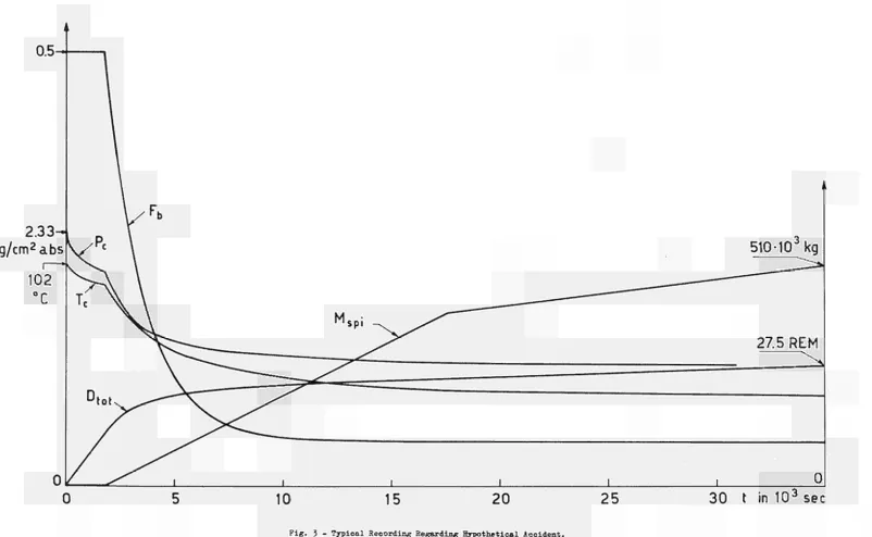
3.4 Presentation of Some Illustrative Results
Figs.2 and 3 give the results relative to a hypothetical accident, in which
both the blowdown of the primary coolant and the release to the free volume
of the containment building of the various energy contributions of nuclear
and/or chemical origin have been assumed to take place instantaneously at
the moment t=0 of the accident.
In Fig.2, Ρ denotes the absolute pressure inside the containment
building, E
1through,E denote the heat flows exchanged by the various
internal and external structures with the free volume of the containment building,
E
represents the heat flow delivered to the free volume due to fission product
decay, and D
represents the total dose incurred to the thyroid due to
iodine inhalation.
Fig.3, which refers to'the same accident as Fig.2, gives furthermore
the temperature transient inside the free volume (T ) , as well as the time
dependence of F,(t). It is noted that the internal spray system entered into
operation 1/2 hour after the initiation of the accident. The total mass of
3
internal spray coolant, M ., is given as a function of time. For M . î> 400x10 kg
*
Jspi
spi
the mass flow rate of the internal spray system is reduced by a factor of 4.
4. DESCRIPTION OF THE DIGITAL CODE
4.1 General Aspects
As mentioned before, in order to acquire a readily available computation
tool, the mathematical model as described in chapter 2, was programmed for
24
with the analog model.
The PREST code has been written in Fortran IV for use in connection with the IBM 360/65 computer. The code is capable of producing plots (by means of the calcomp device) of pressure, temperature, and integrated dose-rate versus time, if so specified by the user.
The PREST code foresees, contrary to what is the case for the analog model, the calculation of temperature and pressure transients inside the containment building, also during theiblowdown phase.
In order to save computer time it is advisable to compute the total transient by means of different subsequent runs, having different time steps. The output values of the various quantities for a certain run have then to be used as input for the subsequent run.
4.2 Structure of the Digital Code
The PREST code consists of the following parts:
a) MAIN Program. This carries out:
- reading of input data and control parameters, - calling of various subroutines,
- computation of mass and energy values at each time step, - printing of results.
b) CONT subroutine. This carries out, for each time step, the computation of the values of temperature, pressure, etc., of the water-steam-air mixture inside the free volume of the containment building.
c) DTAU subroutine. This carries out the computation of the radiation dose to the thyroid due to radioactive iodine, as a function of height of release, distance, time of exposure, atmospheric categories considered, and wind velocity.
the containment building (also represented in slab geometry) having one boundary in contact with the inside atmosphere and one boundary in contact with the outside atmosphere. The heat transfer coefficients and the temperature distributions are calculated; the former may also be independently specified by the user.
The present version of the PREST code comprises:
6 ISLB subroutines, of which ISLB5 and ISLB6 are dummies, 4 ESLB subroutines, of which ESLB3 and ELSB4 are dummies. e) DECAY subroutine. This determines, as a function of time, the total energy
released by fission product decay, following infinite reactor operation. Shure-Dudziak data are used for this purpose [[3]. f) BLWDWN subroutine. This determines for each time step the mass and energy
increments, inside the free volume of the containment building, due to the blowdown of high enthalpy coolant.
g) IRWIN and ERWIN subroutines. These read and print input data for ISLB and ESLB subroutines, respectively,
h) IPRINT subroutine. This prints the temperature distribution of the internal and external slabs.
4.3 Equations for the Digital Code
The equations given in chapter 2 are valid also here. In addition some expressions are used exclusively for the digital code; they are given in the following.
As pressure computation can only be carried out, by the CONT subroutine, if there is liquid water in thermodynamic equilibrium with steam, it is
assumed that before blowdown initiates the atmosphere inside the containment building is saturated. In order to satisfy this saturation condition the
code automatically evaluates, for the case that zero mass of water is specified in the input by the user, from the input data for volume, pressure and
temperature, the mass of water initially present. Hence, M the initial mass w,tot
P°.V° w,tot R > T
c, abs with
26
. w moljW (55)
P° = P°(T°)
g g c (56)
in accordance with steam table data.
The initial mass of water is evaluated giving the following input data: V , Ρ , , Τ . The mass of air is to be given in input.
The mass rate of injection of primary coolant due to the blowdown process, Γ , and the relevant specific internal energy,U, ,, are given in the code
by expressions which allow them to be adjusted within a relatively wide range of time dependences in accordance with the results of separate experimental and/or theoretical evaluations:
r
b d
( t ) = Kbdi
+W*
+här*'
for t ί τΛ bdl
Ρ ,** ,„ „ 2 . "(t_Tbdl)/Kbd4 '
r
bd
( t ) = (Kbdl
+WVl
+WW"
8for t >/ y τ
bdl
(57)
U
bd
( t ) = Cbdl
+W*
for t « xb d 2"(t"rbd2)/Cbd4
Uvj(t) = (C, ,, + C, ...τ, ,. - C, , _ ) . e + C, ,. bd bdl bd2 bd2 bd3 bd3 for t "fr τ bd2
(58)
The mass and energy rates of injection relative to the internal spray system are step-wise adjustable as a function of time:
Γ .(t) = 0 spi for t ^ τ
spi (59)
Γ .(t) = Γ . , = constant spi spi,!
,^\
\
spi,nl
spi,η
Τ .(t) = Τ .
= constant J
*
'
*
'
spi
spi,η
The number of different values, n , of Γ . and Τ .
that can be
spi,η
spi,η
specified by the user may be at most 6.
4.4 Numerical Methods for the Digital Code
The methods of numerical solution for the various expressions, in particular
for the energy balance (eq.l), for the Fourier equation for heat conduction
(eq.20), and for the dose determination (eqs.(26) through (38))are briefly
outlined in the following.
4.4.1 Solution of the Energy Balance
Equilibrium values of pressure and temperature of the atmosphere inside
the containment building are computed at each time step by subroutine CONT.
The equation:
E
tot
(t)=
Eî o t
(V
(62>
in which E^ . (t) and E^. . (T ) represent the lefthand and righthand side
tot
tot c
of eq.(l), respectively, is solved by using the Newton method. The flowchart
of this part of subroutine CONT is shown in Fig.5 . The trial and error
calculation stops if one of the following convergence tests is satisfied:
¡E. .(t) E* (T ) |
_
tot
tot c
s< 1 0 7
( 6 3 )E
t o t
( t )A T
cI
4
\< 5.10
(64)
T
c
where ΔΤ is the difference between two consecutive trial temperatures.
At each calculation step the quantities:
28
are evaluated by linear interpolation in tables of saturated water and steam
properties. The enthalpy, H. (T ) , of liquid water, is not given in the code
in tabular form, because H. in kcal/kg may be assumed equal to Τ in C in
the range of interest (the error is less than 1%).
The following equation has been used to evaluate the density of water
at saturation conditions :
(65)
— : v, = (9.85).10
4+ fe.9).10~
7.T
p,
1
x'
v'
c
3
with
ν
expressed in m /kg, and
Τ
expressed in C.
In order to save computertime the assumption is made that the volume
occupied by gas does not change during the trial and error calculation for
one step, i.e., the new free volume is computed for each time step only after
convergence for Τ has been reached. It was shown that the error introduced
by this simplification is unappreciable.
4.4.2 Solution of the Fourier Equation for Heat Conduction
In order to determine the heat exchanged with structures inside the
containment building as well as the heat exchanged with the outside atmo
sphere (eq. 2 0 ) , the internal structure and the outside shell of the contain
ment are tireated, as said before, in slab geometry.
Each slab is subdivided in a number of layers, which, contrary to the
case for the analog model, are chosen of equal thickness, Δχ, for a particular
slab. Quantities referring to an arbitrary layer n, are distinguished by means
of the subscript n, where η covers the values 1 through n* (n has, in general,
a different value for each slab). The layer n=l is always in contact with
the inside atmosphere of the containment building, be it for internal or
external slabs. The layer n=n is, for the internal slabs, iö contact with
the adiabatic midplane, whereas for the external slabs it is in contact with
The resulting finite difference system of equations, written here for the n layer of the i internal slab, is
i,n i,n C.
i,n L
„1+1 1+1 1+1 1+1
T. τ. τ. τ . ¿Λ
i,n+l i,n _ i,n i,nl R · . Λ R · ι J
i,n+l,n i,n,nl J
π
2:
x1 τ!
Τ!
Τ! ΙΊΊ
Qv I i,n+l i,n l.n i,n-l I
5
· h^r;——
t
—M J
v i,n+l,n i,n,n-l ' J
(66)
with
X X
η = η -1, η -2,...,2;
1 denotes the number of the time-step, having values 0,1,2,...; At denotes the length of the time-step (equal for all steps); θ represents a real quantity, comprised between 0,5 and 1.
In view of allowable truncation errors when using words of 32 bits, Δχ and Δι have to be chosen such as to respect the following expression:
Θ.Δΐ R. x1 .C.
i,n+l,n i,n
>y 1 0 " (66a)
The boundary conditions for surfaces in contact with the internal atmosphere are given, f or internal slabs , by:
1 ρ „ ,ml+l ml . . ,. „N ,ml
f ì -
R
with
i,l,c
.Ce.(Tt
Tt · T
X) + (i-e).(Tt . - τ
1)
3
i,l c i,l c
(67)
R
-
i Δχ
J^
ι,Ι, c 2 k. ι, m s , int h. ' ι i,c
(68) The heat transfer coefficient, h. , between the surface and the internal
i,c
atmosphere of the containment building can be either specified in input as a constant, or evaluated on the basis of the following correlation:
ht = (19.31).ρ
i,c
• ρ (t).
7 T1ι,Ι
(69)with
,1 , . kcal h. expressed in —-ζ ;
i,c r 2 , on '
30
T and Τ.
expressed in C.
The value at time t of the density of the airsteam mixture, ρ (t),
is given by:
M°
p
c
( t ) vftT
+ pg
( t ) (70)For internal slabs the boundary condition for layer η is, of course,
1 χ
f = 0 (as said before, layer η is in contact with the adiabatic midplane),
i
For external slabs, the same equations (67) through (70) are valid
regarding the boundary conditions for surfaces in contact with the internal
atmosphere ; only one has to substitute the subscript i by j .
The boundary conditions for surfaces in contact with the external
atmosphere are given, for external slabs only, by:
fi-
Θ. ( τ1 ^ τ1"1"1) + (ΙΘ).(Τ1 τ1(71)
j
R.
».
ext
*
'
»vt
.
u
3,ext,n* L
3»η
1
>η
Jwhere
R.
.
=
~
. :—· + R. .
+ r — —
(72)
3,ext,n
2
k..
3,ms,ext
h.
&χ±The heat transfer coefficient, h.
., between the external surface of
th
3»
e x tthe j
external slab and the outside atmosphere is given by:
hí
. = C'
+ C"
. I T 1 T
1I
(73)
3,ext
ext
ext
' a,ext
j *
j,n
for the case of air cooling,
or by:
h.
= constant
(74)
3 ,ext
for the case of cooling by means of the external spray system.
The above system of equations (eqs. (66), (67) and (71)) was solved by using
the method described in £ll] , chapter VI. This method was, amongst others,
slabs do not depend on spatial coordinate and temperature.
4.4.3 Solution of the Equations for Dose Determination
The equations of chapter 2, point 2.3, are valid also here.
The function f (d,h) is evaluated by the subroutine DTAU, for each value of the distance, d, specified by the user, by computing the expression:
2
i r__ü 1
2 * Lc
z(d,MC)J
f ( d>h'M C ) = π.£σ (d,MC).a (d,MC) + c.B3 ( 7 5 )
y z
for all metereological categories, specified to be considered for the site in question, and choosing the maximum value. The values for the height of release, h, the crosssectional area of the containment building, B, and the factor c are input quantities (the code assumes c =0.5, unless otherwise specified by the user).
The functionsσ (d,MC) and ar (d,MC) are incorporated in the code in tabular form, with 100 m « d ¿ 100,000 m, and MC = A, Β, C, D, E, F in accordance with [9].
The code computes on the basis of eqs. (26) through (38) the dose incurred to the thyroid by iodine inhalation versus time for the first distance,
d.^ loO m, specified by the user, and presents a graph of the results. For any other distance, d > d , the code computes and prints only the ratio
D ( dn>
D(d1) *
The curves of dose versus time for the various distances differ only by the above defined factors, as the time of transport of the iodine from the point of release to the point considered is not taken into account in the model used.
32
The rate, L(t), is determined on the basis of the function of leak-rate versus over-pressure (which is to be given as input in tabular form), using for the pressure in the containment building the values computed, at each time step, by subroutine CONT.
The function F (t) is to be specified in input, and is either a constant F (/ 0) or a function of time to be given in tabular form.
Ρ
The function F (t) is determined in accordance with eqs. (28) and (29), in which a, F , τ . and τ, are to be supplied in input.
4.5 Computer Code Usage
4.5.1 Coding Language
The PREST code.is written for the IBM 360/65 computer in FORTRAN IV language. The object deck, available at the CETIS Computation Center of Euratom, Ispra, Italy, was obtained from the source deck by means of the FORTRAN H Compiler using the optimization 2 option.
4.5.2 Input Data Sheets
Card Format Fortran
Name Description Units
TOO (18A4) TITLE Any alphameric character string to identify the problem
MOO (1015) ISW1 Printing Parameter: if ISW1 =0 short output
¿O full output
ISW2 Blowdown Parameter: if ISW2 =0 no blowdown
¿0 blowdown occurs
ISW3 Decay Heat Parameter:if ISW3 =0 no decay heat addition ^0 decay heat is considered
ISW4 Dose Calculation Parameter: if ISW4 =0 no dose calculation
5*0 dose calculation is performed
ISW5 Internal Spray Parameter: if ISW5 =0 no internal spray
^0 internal spray is considered
ISW6 External Spray Parameter: if ISW6
=0 no external spray
*Ό external spray is considered
ISW7 Chemical Heat Parameter: if ISW7 =0 no chemical heat addition
¿0 chemical heat is considered
ISW8 Nuclear Heat Parameter: if ISW8 =0 no nuclear heat addition ^0 nuclear heat is considered
IPL0T Plotting Parameter: if IPL0T =0 no plotting
^0 results are plotted by means of Calcomp device
IPRCY Printing Control Parameter: if IPRCY =0 results are printed at each
time step
34
Input Data Sheet 2
MOI (3I10,3F10.0) NIHC NEHC MAXTHE DTHETA THETA DOSE
Number of internal slabs (¿4) Number of external slabs (v< 2)
Maximum number of time steps Time step value
Initial value of time for the run Initial value of dose for the run
hr hr REM
M02 (7E10.0) VCO Free volume of the containment m building at time t=THETA
MWO Mass of water (liquid+vapour phase) kg present in the containment building
at time t=THETA. If MWO=0 in input, the program computes the amount of water needed to saturate the air contained in the free volume of the containment building and sets MWO to this value
ETO Total energy of the airsteamwater Kcal mixture in the containment building
at time t=THETA. ETO is computed by the program if MWO is set to zero in input
ι
PCO Value of total absolute pressure in Kg^/cm' the containment building at time
t=THETA
TCO Temperature in the free volume of containment building at time t=THETA
POWER Nominal reactor power CHOI 2(E10.0) ECHEM
TCHEM
Total energy of chemical origin introduced into the free volume of the containment building Time constant for the release of energy of chemical origin
Mw
Kcal
NU01 2(E10.0) ENUCL Total energy of nuclear origin intro- Kcal duced into the free volume of the
containment building
TNUCL Time constant for the release of hr energy of nuclear origin
SP01 (E10.0, 110, 5E10.0)
TAUSPI Value of time at which the internal hr spray system enters in operation,
τ spi
NTM Number of different operating condi- — tions of the internal spray system;
NTM N< 6
TTSP(I) (1=1,NTM) values of time at which the hr operating conditions of internal
spray system are changed
SP02 (6E10.0) XMAS(I) (1=1,NTM) values of mass flow rate for kg/hr the different operating conditions
of the internal spray system
SP03 (6E10.0) XENR(I) (1=1,NTM) values of water temperature at nozzles outlet corresponding to the different operating conditions of internal spray system
101 (5E10.0, 215)
XL
XK
CP
R0
NI
NF
Surface area of one face of a slab m
m Thickness of a half-slab
Thermal conductivity of slab material Kcal/m.hr. C
Specific heat of slab material
Density of slab material Kg/m" Kcal/Kg. C
3
Number of layers of equal thickness in which a half-slab is subdivided
3S
Input Data Sheet 4
102 (2E10.0) CS Value of the heat transfer coeffi cient to be specified only if NF=0 in card 101
RINS Thermal resistance of thermal insu lation or protective paint, per unit surface area
Kcal/m?hr.°C
m2hr°C Kcal
103 (7E10.0) T(I) Mean temperature of a layer of an internal slab. NI values of Τ have to be supplied in a sequence starting from the adiabatic mid-plane of the slab
EOI 5E10.0,
315) S
XL
XK
CP
R0
NI
NF
NA
Surface area of one face of a slab m
Thickness of external slab m
Thermal conductivity of slab material Kcal/mhr. C
Specific heat of slab material
Density of slab material Kg/m" Kcal/Kg.C
3
Number of layers of equal thickness in which an external slab is subdi vided
Control parameter for the calculation of the heat transfer coefficient bet ween a slab and the inside atmosphere If NF=0 the heat transfer coefficient is assumed constant and equal to CS. If NF^O the heat transfer coefficient is evaluated according to equation (69)
Control parameter for the calculation of the heat transfer coefficient bet ween a slab and the external atmosphere, or water of the external spray system NA=0 the external surface is assumed
adiabatic
NA^O the heat transfer coefficient is evaluated by means of equation
cient to be specified only if NF=0 in card EOI
CXI Constant C' of equation (73)
CX2 Constant C" of equation (73) e xx
TA Temperature of air outside the containment building
RINSI Thermal resistance of the thermal insulation or protective paint, per unit surface area, on internal face of external slab
RINSE Thermal resistance of the thermal insulation or protective paint, per unit surface area, on external face of external slab
Kcal/m . h r . C
Kcal/m . h r . C
m2.hr.°C/Kcal
m . h r . C/Kcal
E03 4E10.0) TAQ Temperature of the cooling medium of C the external spray system at the
outlet of the nozzles, to be specified only if ISW6j*0
GAM Mass flow rate of the external spray Kg/hr system, to be specified only if ISW6^0
TAUSPE Value of τ , to be specified only hr if ISW6*0 S p e
CX Value of the heat transfer coefficient Kcal/m. hr. C between the external slab and the
cooling medium of the external spray system
E04 (7E10.0) T(I) Mean temperature of a layer of an °C external slab.NI values of Τ have
to be supplied in a sequence start ing from the external surface of the slab
COI (315) LASST Lowest index to be used for inter polation in steam tables. It may be specified larger than 1 to save machine time
MASST Highest index to be used for inter polation in steam tables. It may be specified smaller than NASST to save machine time
38
Input Data Sheet 6
C02 (4E12.0) TSAT(I) Saturation temperature C 2
PSAT(I) Saturation pressure Kg .-/cm 3
RHOG(I) Density of saturated vapour Kg/m
HLG(I) Specific heat of evaporation Kcal/Kg
C03 (2E10) MAO Mass of air in the free volume Kg of the containment building
CVAIR Specific heat of air at constant Kcal/Kg. C volume
D01 (7E10.0) FBO
ALFA
TAUB
FPO
UAVG
HEIGHT
Value of F in equations (28) and (29); FBO is assumed equal to 0.5 if not specified in input
Value of α in equations (28) and (29)
Time constant for the removal of hr radioactive iodine from the internal
atmosphere of the containment build ing, eq.(29), to be specified only if ISW5?!0
Fraction of the total inventory of the iodine in the fuel which is released from the primary cooling system into the free volume of the containment building. If FPO is not specified here,a table of F =F(t) must be supplied (see cardspD07, D08)
Mean wind velocity m/hr
Height of radioactive source above m the ground
Fraction of cross-sectional area of the containment building which is taken into account for the "shadow" effect"
D02 (2E10.0) BAREA Cross-sectional area of the contain- m ment building in cross-wind direction
3 BRATE Breathing rate of a standard adult m /hr
man
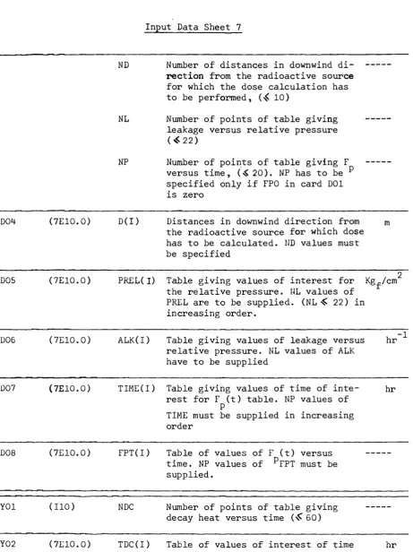
ND Number of distances in downwind di
rection from the radioactive source
for which the dose calculation has to be performed, (4 10)
NL Number of points of table giving leakage versus relative pressure
(«22)
NP Number of points of table giving F versus time, (·$20). NP has to be p
specified only if FPO in card D01 is zero
D04 (7E10.0) D(I) Distances in downwind direction from the radioactive source for which dose has to be calculated. ND values must be specified
D05 (7E10.0) PREL(I) Table giving values of interest for the relative pressure. NL values of PREL are to be supplied. (NL « 22) in increasing order.
Kg /cm
D06 (7E10.0) ALK(I) Table giving values of leakage versus relative pressure. NL values of ALK have to be supplied
hr 1
D07 (7E10.0) TIME(I) Table giving values of time of inte rest for F (t) table. NP values of
Ρ
TIME must be supplied in increasing order
hr
D08 (7E10.0) FPT(I) Table of values of F (t) versus time. NP values of PFPT must be
supplied.
Y01 (110) NDC Number of points of table giving decay heat versus time (^õO)
Y02 (7E10.0) TDC(I) Table of values of interest of time after shutdown. NDC values of TDC have to be supplied in increasing order
hr
Y03 (7E10.0) EDC(I) Table of values of fission products ■ decay power expressed in per cent of the nominal reactor power. NDC values
[image:43.595.50.512.82.699.2]40
Input Data Sheet 8
BOI (5E10.0) TAUB1
KBD(l).
KBD(2)
KBD(3)
KBD(4)
Coefficient of equation (57)
Coefficient of equation (57)
Coefficient of equation (57)
Coefficient of equation (57)
hr
Kg/hr
Kg/hr'
Kg/hrc
Time constant relative to the in- hr jection of blowdown water, eq. (57)
B02 (5E10.0) TAUB2 Coefficient of equation (58) hr
CBD(l) Coefficient of equation (58) Kcal/kg
CBD(2) Coefficient of equation (58) Kcal/Kg.hr
CBD(3) Coefficient of equation (58) Kcal/Kg
CBD(4) Time constant relative to the hr energy of blowdown water, eq. (58)
In order to facilitate the preparation of the input data required by the program PREST, some additional information is given in the following.
All the data have to be supplied in the order specified by the preceding
input sheets and must be punched on standard IBM-Cards in columns 1 through 72 in accordance with the format specifications given for each card.
All data are given in the form of floating point or fixed point numbers, except for TITLE in card TOO, which is alphabetic.
For further clarification of the usage of the code the following observations are made :
1)- Card TOO is the first card and must always be present. It is recommended to leave the first column blank. All other columns may contain any alpha-meric information which will be printed on the output to identify the problem and will appear also on the plot of the results.