http://dx.doi.org/10.4236/jsip.2013.44052
Centerline Extraction for Image Segmentation Using
Gradient and Direction Vector Flow Active Contours
Shuqun Zhang1, Jianyang Zhou2
1
Department of Computer Science, College of Staten Island, City University of New York, New York, USA; 2Department of Elec-tronic Engineering, Xiamen University, Xiamen, China.
Email: [email protected], [email protected]
Received September 19th, 2013; revised October 19th, 2013; accepted October 26th, 2013
Copyright © 2013 Shuqun Zhang, Jianyang Zhou. This is an open access article distributed under the Creative Commons Attribution License, which permits unrestricted use, distribution, and reproduction in any medium, provided the original work is properly cited.
ABSTRACT
In this paper, we propose a fast centerline extraction method to be used for gradient and direction vector flow of active contours. The gradient and direction vector flow is a recently reported active contour model capable of significantly improving the image segmentation performance especially for complex object shape, by seamlessly integrating gradient vector flow and prior directional information. Since the prior directional information is provided by manual line draw-ing, it can be inconvenient for inexperienced users who might have difficulty in finding the best place to draw the direc-tional lines to achieve the best segmentation performance. This paper describes a method to overcome this problem by automatically extracting centerlines to guide the users for providing the right directional information. Experimental re-sults on synthetic and real images demonstrate the feasibility of the proposed method.
Keywords: Image Segmentation; Active Contours; Gradient Vector Flow; Direction Vector Flow
1. Introduction
Image segmentation is to separate an object of interest from the rest of an image. It is one of the most important and yet difficult problems in image processing and com- puter vision, which has been addressed by many algo- rithms, among which, active contours, also known as snakes, have been extensively studied and used since they were first introduced by Kass etal. [1]. Active con- tours are dynamic curves modeled to evolve towards the object boundary by minimizing some given functional energy. Since designing external force is the key for the performance of active contours, many external forces have been proposed [2-7] such as Cohen and Cohen’s balloon force [2], Park and Chung’s virtual electric field [3], Xie and Mirmehdi’s magnetostatic field [4], Sum and Cheung’s boundary vector field [5], Li and Acton’s vector field convolution [6], and Xu and Prince’s gradient vector flow (GVF) field [7]. Among them, the GVF is the most widely investigated external force field, which is com- puted as a diffusion of the gradient vectors of image edge map. The GVF field has the advantages of larger capture range and the ability of pushing the fronts of active con- tours into concave boundaries over the traditional exter-
nal force. Due to these advantages and being easily ex- tended, many works have followed the original GVF mo- del to further improve the performance. For example, the generalized GVF [8] improved the convergence of active contours to long, thin boundary indentations [8]. Xie etal. [9] modified the GVF, so it can be more robust to image noise. Ray etal. [10] incorporated the motion direction into the GVF model for tracking rolling leukocytes. The GVF field has been also modified by considering the directional information of image edge to make active contours discern the image edge with different directions [11].
contour initialization step. Correspondingly, a novel ex- ternal force called gradient & direction vector flow (G & DVF) [12] was developed to seamlessly integrate the GVF field and the direction vector field produced by the directional lines drawn by a user. This is a very simple method for providing prior information and can be used for any images. It has been also demonstrated that the G & DVF field can significantly improve the performance of the GVF model on segmenting images with complex object shape, and can alleviate the requirement that the initial contour must be very close to the true object bound- ary in order to obtain a good performance. However, since the directional information is provided by user mouse clicks, it is inconvenient particularly for those inexperi- enced users who might not be able to find the best place to draw the directional lines on the image for the algo- rithm to be effective. This paper proposes a method to automatically extract centerlines of objects and concaves, which can be used to guide the users where the direc- tion lines should be drawn on the image to obtain the best segmentation performance. The feasibility of the pro- posed method is demonstrated by experiments tested on both synthetic and real images.
The rest of this paper is organized as follows. Section 2 reviews the related active contour models and describes the proposed centerline extraction method. Then, the experimental results and discussion are provided in Sec- tion 3. Finally, we present our conclusions and future work.
2. Method
2.1. Classical Active Contour
The classical active contour [1] is usually modeled as a dynamic curve x(s) = [x(s), y(s)], s[0,1], that evolves from an appropriate initial position to the object bound- ary by minimizing the following energy functional
1
2
2 1
AC 0 0 Ext
1
d 2
E x
x' s x'' s s
E x s ds(1) where α and β are positive weighting parameters. The first and second terms are the internal energy and ex- ternal energy, which are used to regularize the smooth- ness of the curve x and attract the curve x toward the object boundary, respectively. The function EExt in the
external energy is usually defined as the negative inten- sity of the image edge map f, which is computed by first smoothing the image I with a Gaussian kernel followed by a gradient to enhance the boundaries as
Ext , , , ,
E x y f x y G x y I x y (2)
where Gσ(x, y) denotes a Gaussian filter with standard deviation σ. The minimization of EAC can be achieved by
evolving the front of the active contour dynamically as a function of parameter s and artificial time t given by
,
,
, Extt s t s t s t E
x x x , (3)
where the first term and the second term are generally called the internal force and the external force, respec- tively. The classical active contour has poor performance in image segmentation, and thus many improvements have been proposed, among which the GVF has received many attentions.
2.2. Gradient Vector Flow
The GVF is an external force proposed to overcome the two main drawbacks of the traditional active contours: limited capture range and poor convergence to concave boundary. It substitutes the traditional external force
Ext E
in Equation (3) with the GVF field v(x, y) = [u(x,
y), v(x, y)], which is derived from the diffusion of the gradient vectors of the image edge map, and is set to minimize the following energy functional
2 2 2GVF d d .
E v
v f v f x y (4)In Equation (4), the first term in the integrand is used to smooth the vector field v, and has the effects of mak- ing the force field robust to image noises and enlarging the capture range of the force field, while the second term is the data fidelity term that keeps v being equal to the gradient vector of the edge map f where the magni- tude of f is relatively large. µ is the smoothness regu- larization parameter.
The GVF field can be obtained by solving the follow- ing Euler-Lagrange equation
22
,
t t f
v v v f (5) which is derived from the variational minimization of the energy functional EGVF with respect to v.
2.3. Gradient and Direction Vector Flow
directional lines to point to the direction that the front of active contour should evolve. The proposed G & DVF minimizes the following energy functional
G&DVF GVF DVF ,
E v E v E v
(6)where EGVF and EDVF denote the GVF functional and the
direction vector flow (DVF) functional that is generated by the directional lines, respectively. The functional EDVF
is defined as
2 2DVF d d ,
E v
w vw x y (7)where w is the DVF filed obtained by drawing a direc- tion line in the image, and represented as
, if
, is on ,, otherwise,
x y x y
b a
ab
w b a
0
(8)
where a and denote the starting and the end point of the directional line , respectively. If multiple lines are needed, we can simply add the corresponding direction vector fields together.
b
ab
The DVF functional in Equation (7) is designed to keep v being equal to w where the norm of w is relatively large. The influence of the directional lines on the exter- nal force field v is controlled by the parameter η. The G & DVF field can be obtained by solving the following Euler-Lagrange equation
2
22
0.
f f
v v vw w (9) The gradient decent of Equation (9) can be obtained by
2
2
,
t f f
v v v v w w2 (10)
[image:3.595.308.537.85.335.2]with parameterizing the descent direction by an artificial time t > 0. The solution of Equation (10) can be obtained when the iterative process of the gradient decent is at the steady state.
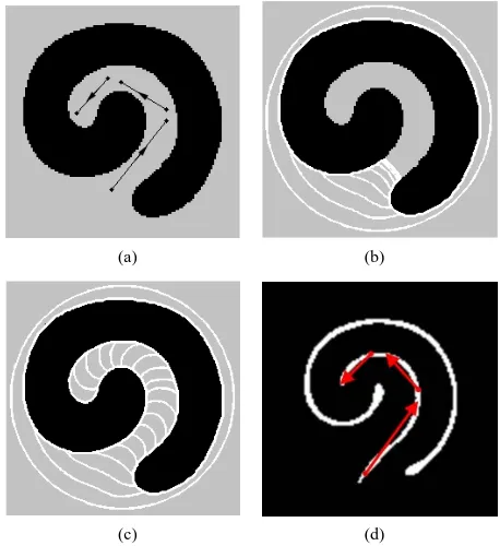
Figure 1 shows an example of the usage and effec- tiveness of the G & DVF. The object to be segmented is a synthetic swirl shape image as shown in Figure 1(a).
Figures 1(b) and (c) give the segmentation results of the GVF and G & DVF, respectively. It is seen from Figure 1(b) that the GVF active contour cannot conform to the object boundary from the circle-shaped initialization out- side of the object. The contour is stuck at the entry of the object. The rolling concave in the object is too difficult for the GVF active contour to handle. However, if we simply place three short lines inside the rolling concave pointing inward as shown in Figure 1(a), the G & DVF can easily move the initial contour into the rolling con- cave, as shown in Figure 1(c).
2.4. Centerline Extraction for G & DVF
The G & DVF has been proven to provide much better
(a) (b)
(c) (d)
Figure 1. Demonstration of the usage and effectiveness of the G & DVF: (a) The image to be segmented; (b) Front propagation of the original GVF active contour; (c) Front propagation of the G & DVF active contour; (d) The ex- tracted centerlines and the produced directional lines.
performance than the GVF and other active contour mod- els, especially when dealing with complex object shapes and weak-edge-leakage [12]. However, it is inconvenient in the sense that the DVF field is produced by user draw- ing lines. An inexperienced user may have difficulty in finding the best place to draw the lines to achieve the best performance. Since the G & DVF will have the best segmentation performance if the lines are drawn along the centerline of the object or concave, it would be con- venient if the centerline is provided to the user. Hence here we propose to extract the centerlines automatically to help users in using G & DVF active contours, which is based on the method for detecting saddle/stationary points [13] and curve skeletons [14].
an edge indicator function g x y
, 1 1 f x y
, can be used to multiply with the magnitude of the gradient of GVF field since the edge function is very small when the pixel at (x, y) is on the strong edge and has a value of 1 in other places. In summary, centerlines can be extracted by first calculating the product of the magnitude of the gra- dient of GVF field and the edge indicator function,
,
,
,k x y g x y v x y , (11) then normalizing it to [0, 1],
,
,
min
max minq
k x y k
k x y
k k
,
(12)
and finally comparing with a threshold
, 1
,0 ,
if k x y T s x y
else
,
,
(13)
where T is a pre-set threshold between 0 and 1. In Equa- tion (12), q is the field strength taking a value between 0 and 1, which can be used to control the centerline strength. Morphological operations such as opening can be applied to process the threshold result
,s x y B (14)
where B is a structuring element, and “o” denotes a morphological opening operation. If necessary, thinning or skeleton algorithm can be further used to make the extracted lines thinner. Once the centerlines are extracted, the G & DVF users will know where the best place is to draw the directional lines and generate the DVF field. That is, the users can just simply follow the detected cen- terlines to draw the directional lines. As an example, Fig- ure 1(d) shows the centerline extraction result from Fig- ure 1(a) using the proposed method described above, where lines outside the object support has been removed. The required directional lines (shown in red color) for the G & DVF can be easily obtained based on Figure 1(d), which are similar to the lines shown in Figure 1(a).
It is noted that the proposed method has very low com- putational complexity since it simply utilizes the already computed GVF for centerline extraction and there is no much extra calculation needed.
3. Experimental Results
To demonstrate the feasibility of the proposed method, we present experiments tested on both synthetic and real images. The image size is 120 × 120 pixels for the tested synthetic image, while is 240 × 240 pixels for the tested real image. In the experiments, the edge maps for com- puting the force fields are normalized to the range [0, 1]. The parameters α = 0.8, β = 0.0, and µ = 0.2 were chosen for both the G & DVF and the GVF, and η = 1.5 for the
G & DVF. The field strength q = 1 is used. The GVF and G & DVF active contours use the same circle-shaped ini- tializations in each of our experiments, which are not plac- ed in the neighborhood of the desired object boundary.
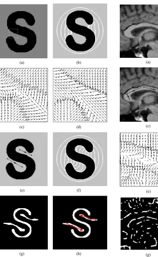
Figure 2 shows an experiment tested on a synthetic “S” shape image. The original image is shown in Figure 2(a). The two semi-closed concaves formed in the “S” shape are difficult for the original GVF field to handle and the contour is usually stuck at the entries. This can be seen from Figure 2(b) that shows the segmentation result using the original GVF model. The failure of seg- mentation using the original GVF is because there are some GVF field vectors pointing outward at the entry of the semi-closed concave as shown in Figure 2(c), which prevents the front of the GVF active contour moving into the semi-closed concave boundary. For better segmenting the “S” shape image, we can use the G & DVF and draw two directional lines at the entries of the two semi-closed concaves as shown in Figure 2(e) to force the field vec- tor to point inward. The field vector change from out- ward to inward is demonstrated in Figure 2(d), which shows the G & DVF field vectors at the entry of the semi-closed concave. The changing of field vector direc- tion helps the front of the G & DVF active contour exact- ly propagate into the semi-closed concave as shown Fig- ure 2(f). The two drawn lines shown in Figure 2(e) ac- tually can be extracted using the proposed method. Fig- ure 2(g) shows the detection result of the centerlines us- ing the proposed method. Given Figure 2(g), the G & DVF users will know where exactly to draw the direction lines, simply following the centerlines as shown in Fig- ure 2(h). Alternatively we can also automatically pro- duce a line by finding the two end points of a detected area.
Another experiment was performed on a real corpus- callosum MRI image as shown on Figure 3(a). The ac-tive contour is initialized at one end of the corpus-callo- sum. We expect that the front of the active contour moves into a hooked concave for exactly conforming to the cor- pus-callosum boundary. The segmentation result using the original GVF model is given in Figure 3(b), where the GVF field obviously cannot drive the front of the GVF active contour to move into the hooked concave, and the front of the GVF active contour stops moving at the beginning of the hooked concave. With the G & DVF active contour, simply drawing three directional lines on the image will assist the curve evolution, as shown in
Figure 3(c). The corresponding segmentation result by the G & DVF is shown in Figure 3(d). It successfully drives the front of the active contour to the correct object boundary from the circle-shaped initialization. The ob- tained different results for these two models can be ex- plained from their vector fields as shown in Figures 3(e)
(a) (b)
(c) (d)
(e) (f)
[image:5.595.72.386.78.589.2]
(g) (h)
Figure 2. Experimental results of a synthetic “S” image: (a) The original synthetic image; (b) Front propagation of the original GVF active contour; (c) and (d) The GVF field and the G & DVF field within the dashed area of (a), respec- tively; (e) Two directional lines drawn on the image for the G & DVF model; (f) Front propagation of the G & DVF active contour; (g) The extracted centerlines; (h) The direc- tional lines produced on the obtained centerlines.
ferent directions while the G & DVF field vectors point to the same direction because of the force from the three lines. Again we can generate the needed direction lines using the proposed method. The detected centerlines are
(a) (b)
(c) (d)
(e) (f)
(g) (h)
Figure 3. Experimental results of a corpus-callosum MRI image: (a) The corpus-callosum MRI image; (b) Front pro- pagation of the GVF active contour; (c) Three directional lines drawn on the image for the G & DVF model; (d) Front propagation of the G & DVF active contour; (e) The GVF field of a small area in the middle of the corpus-callosum; (f) The G & DVF field of the same area of the corpus-callosum as in (e); (g) The extracted centerlines; (h) The directional lines produced on the obtained centerlines.
[image:5.595.252.527.81.594.2]Figure 4 shows another experiment tested on a real hand image. It is shown in Figure 4(b) that, the GVF active contour cannot conform to the semi-closed con- cave formed by the fingers, while by simply adding a directional line at the entry of the concave, as shown in
Figure 4(a), the G & DVF active contour can converge to the exact hand boundary. The directional line can be generated based on the centerline of the concave, which is extracted using the proposed method and shown in
Figure 4(d).
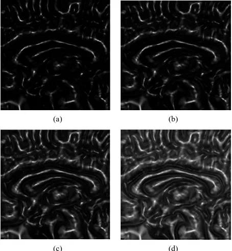
In the proposed method, the centerline strength can be controlled by changing the value of the field strength q in Equation (12). To study the effect of the field strength on the centerline strength, we vary the value of q and apply Equation (12) on the corpus-callosum MRI image given in Figure 3(a). The results are obtained as shown in
Figure 5. It is obviously seen that decrementing the field strength q will enhance the centerline strength.
4. Conclusion
The recent reported G&DVF active contour provides a very good performance in segmenting images with com- plex object shapes and dealing with the issue of weak- edge-leakage. To overcome the problem that the direc- tional information is manually provided in the G & DVF model, this paper proposes a fast semi-automatic method for producing directional information by extracting cen-
(a) (b)
(c) (d)
Figure 4. Experimental results of a hand image: (a) The hand image; (b) Front propagation of the GVF active con- tour; (c) Front propagation of the G & DVF active contour; (d) The extracted centerlines and the overlapping direc- tional lines.
(a) (b)
(c) (d)
Figure 5. Effect of the field strength q on the centerline strength: (a) q = 1.0; (b) q = 0.8; (c) q = 0.6; (c) q = 0.4.
terlines of objects and concaves. The extracted center- lines can effectively guide users to provide the best direc- tional information for the G & DVF model to achieve the best image segmentation performance. Experimental re- sults show the feasibility of the proposed method. Future work will develop fully automatic method for producing the required directional lines for G & DVF active con- tours.
5. Acknowledgements
This work was supported by a grant from National Key Technology R&D Program of MOST of China
(2012BAI07B06) and in part by a grant (# 65394-00-43) from The City University of New York PSC-CUNY Re- search Award Program.
REFERENCES
[1] M. Kass, A. Witkin and D. Terzopoulos, “Snakes: Active Contour Models,” International Journal of Computer Vi-
sion, Vol. 1, No. 4, 1988, pp. 321-331. http://dx.doi.org/10.1007/BF00133570
[2] L. D. Cohen and I. Cohen, “Finite-Element Methods for Active Contour Models and Balloons for 2-D and 3-D Images,” IEEE Transactions on Pattern Analysis and Ma-
chine Intelligence, Vol. 15, No. 11, 1993, pp. 1131-1147.
http://dx.doi.org/10.1109/34.244675
[3] H. K. Park and M. J. Chung, “External Force of Snake: Virtual Electric Field,” Electronics Letters, Vol. 38, No, 24, 2002, pp. 1500-1502.
[4] X. Xie and M. Mirmehdi, “Magnetostatic Field for the Active Contour Model: A Study in Convergence,” Pro-
ceedings of the 17th British Machine Vision Conference,
Edinburgh, 4-7 September 2006, pp. 127-136.
[5] K. W. Sum and Paul Y. S. Cheung, “Boundary Vector Field for Parametric Active Contours,” Pattern Recogni-
tion, Vol. 40, No. 6, 2007, pp. 1635-1645. http://dx.doi.org/10.1016/j.patcog.2006.11.006
[6] B. Li and S. T. Acton, “Active Contour External Force Using Vector Field Convolution for Image Segmenta- tion,” IEEE Transactions on Image Processing, Vol. 16, No. 8, 2007, pp. 2096-2106.
http://dx.doi.org/10.1109/TIP.2007.899601
[7] C. Xu and J. L. Prince, “Generalized Gradient Vector Flow External Forces for Active Contours,” Signal Proc-
essing, Vol. 71, No. 2, 1998, pp. 131-139.
http://dx.doi.org/10.1016/S0165-1684(98)00140-6
[8] C. Xu and J. L. Prince, “Snakes, Shapes, and Gradient Vector Flow,” IEEE Transactions on Image Processing, Vol. 7, No. 3, 1998, pp. 359-369.
http://dx.doi.org/10.1109/83.661186
[9] X. Xie and M. Mirmehdi, “RAGS: Region-Aided Geo- metric Snake,” IEEE Transactions on Image Processing, Vol. 13, No. 5, 2004, pp. 640-652.
http://dx.doi.org/10.1109/TIP.2004.826124
[10] N. Ray and S. T. Acton, “Motion Gradient Vector Flow:
An External Force for Tracking Rolling Leukocytes with Shape and Size Constrained Active Contours,” IEEE
Transactions on Medical Imaging, Vol. 23, No. 12, 2004,
pp. 1466-1478.
http://dx.doi.org/10.1109/TMI.2004.835603
[11] H. Park, T. Schoepflin and Y. Kim, “Active Contour Model with Gradient Directional Information: Directional Snake,” IEEE Transactions on Circuits and Systems for
Video Technology, Vol. 11, No. 2, 2001, pp. 252-256.
http://dx.doi.org/10.1109/76.905991
[12] G. Zhu, S. Zhang, Q. Zeng and C. Wang, “Gradient Vec- tor Flow Active Contours with Prior Directional Informa- tion,” Pattern Recognition Letters, Vol. 31, No. 9, 2010, pp. 845-856.
http://dx.doi.org/10.1016/j.patrec.2010.01.011
[13] G. Zhu, S. Zhang, X. Chen and C. Wang, “Novel Gradi- ent Vector Flow-Based Balloon Force for Active Con- tours,” Journal of Electronic Imaging, Vol. 18, No. 2, 2009, pp. 023007-1-023007-8.
http://dx.doi.org/10.1117/1.3132005
[14] M. S. Hassouna and A. A. Farag, “Variational Curve Skeletons Using Gradient Vector Flow,” IEEE Transac-
tions on Pattern Analysis and Machine Intelligence, Vol.
31, No. 12, 2009, pp. 2257-2274.