DEVELOPMENT OF REMOTELY OPERATED BOMB
DISPOSAL ROBOT EQUIPPED WITH OBJECT WEIGHT AND
POSES ESTIMATIONS
RONNY MARDIYANTO, MUHAMMAD QOMARUZZAMAN, HERI SURYOATMOJO Electrical Engineering Department, Institut Teknologi Sepuluh Nopember, Indonesia
E-mail: [email protected]
ABSTRACT
The paper presents development of the prototype of remotely operated bomb disposal robot equipped with object weight and pose estimation. The main mission of the prototype of remotely operated bomb disposal robot is how to move the bomb to safe area. The key issue here is how the robot can safely evacuate the bomb with minimum risk. In order to avoid gripped object detached from the grip, the robot needs to know the object’s weight and pose. In this paper, we also present methods for estimating object’s weight and pose. We estimate the object’s weight by utilizing linear regressions and measuring currents flowing into servomotors. The increasing current flow that goes into servomotors are monitored to estimate the object’s weight. We estimate the object’s pose by using several image processing steps such as color conversion from RGB to HSV, color filter, edge detection, and hough transform. The methods have been implemented in proposed system that consists of several processing units (Raspberry Pi 3, Arduino Mega, Arduino Uno), Brushless Electronic Speed Controller, Robot Arm, Video Sender, Analog Multiplexer, 3DR telemetry, Ardupilot Mega with GPS and compass, and SkyZone 3D Googles. We have tested the proposed system under laboratory condition. It succeeded to lift object up to 257.4 gram of weight. Such ability equal to lift small bomb like C-4 or small IED. The robot’s payload could still be possible to be developed while maintaining robot’s dimension. The maximum distance of the robot to be operated remotely is 236 meter. The robot also succeeded to follow the saved waypoints and passed the rock with maximum diameter of 12 cm. The robot can estimate the object weight with accuracy of 27.25% and object pose with average error of 92.3%. By implementing the proposed system under real condition, the risk during bomb evacuation process can be minimized.
Keywords: Bomb Disposal Robot, Robot Arm, Object Weight estimation, Object Poses, Hough Transform, Linear Regression
1.
INTRODUCTIONOn March 2011, there was a bomb disguised as a book in Jakarta. The bomb exploded as police try to defuse it with their own bare hand. Also, ref (1)has reported that on October 2001 more than 3000 combat in Iraq and 240 combat in Afganistan were death due to bomb attack. Improvised Explosive Device (IED) could be made in various shapes and sizes. It involves road side bombs, suicide car
bombs, etc. In this modern days IED could be so
complicated that it can’t be defused in place. These accidents show that dangerous object must be treated more carefully.
There are several ways used to counter IED in an urban area. One of them is wearing bomb suit to defuse the bomb. Wearing a bomb suit doesn’t mean that the person inside is invincible. Bomb suit
In order to increase the efficiency and simplicity using EOD robot, many efforts had been made.
1. Grasping automation (3; 4; 5). Distance measurement sensor was used to optimize the manipulator approaching and grasping the object. Distance calculated from the sensor is then used as automatic collision avoidance (5). Distance measurement sensor was also used to map the manipulator surrounding. Data of the map is then represented as image for the user to control the manipulator manually or automatically (3). Another automation method to grasp the object is using stereo camera (4). Stereo camera was used to identify the object and measure the distance between object and robot. Distance was obtained by image processing and comparing of two images from two cameras.
2. User interface (6; 7). Some development of EOD robot focused on interface simplicity. One of them used multimodal feedback such as visual, auditory and haptic sense feedback. User interface simplicity is one of the mayor problems of EOD robot. Increasing functionality of EOD robot may cause user interface complexity. Multi modal feedback also was used to make the operator feels robot’s surrounding condition.
3. Robot design (8; 9; 10; 11) Another EOD robot development focused on design research. The Robotics Institute has developed robot that small and tough enough to be tossed into building. This robot is then used to relay information to soldier before enter building (9). Another robot used massive body to increase payload capacities and outdoor capabilities (10). Massive robot bodies allow more space for the robot to add more mechanical improvement such as electric pushing rods. One of them even used secondary gripper to improve gripping dexterity (11).
Although there are many developments in EOD robot there is a rare development focused on operation simplicity. Most of them focused on manipulator capabilities to lift a heavy weight
object or autonomous grasping. Operation
simplicity is important because it can help operator’s mobility. In a tight situation such as explosive disposal, operator may need to evacuate from current position while in the mean time they must operate the robot. For above reasons, we propose an EOD robot with a simplified control operation. The system must be remotely operated and portable so that operator can maintain their mobility.
In order to improve the capabilities and safety for lifting a heavy weight object, we develop a method for estimating object weight by monitoring currents flowing into servomotor of robot arm. Also, we develop a method for estimating object position to assist operator controlling the gripper.
In order to simplify manipulator’s joint control some researches used mini duplicated non-portable manipulator (7). This mini manipulator represents the real manipulator. This method promises simplicity in controlling manipulator. Disadvantage of using this teleoperation method is that it can only be controlled in a fixed ground station. Interface developed in ref (6) used a wearable interface which is good for controlling simplicity, but on the other side it restricts the operator’s mobility. Our system uses common hobbies radio controller interface. This interface is used for its familiarities among radio controllers. The manipulator of the robot is 5 DOF arm with inverse kinematics so that it can ease operator to control manipulator. This system also uses on board mobile visual feedback. By using this method, system comprises simple, small, lightweight, and portable interface.
The proposed system may not use massive robot structure for it decreases indoor exploration capabilities, but it is not too small so that it is able to contain many sensor modules. Large robot size also limits the robot to explore fragile floor or ground. When opposing an opponent large robot size may lack in abilities of hiding and evacuating quickly. We propose robot in a proper size that it’s adequate to bring robotic arm, GPS, sensors, radio transmitter and receiver, mechanical drivers, etc.
This paper organized as follow: Section 2 explains the proposed system including hardware configuration, robot navigation, robot arm, and methods of object’s weight and pose estimation. Section 3 reviews experimental robot performance including performance of the navigation, grasping object, and estimating the object’s weight and its pose. Section 4 concludes the proposed system.
2.
PROPOSALOur proposal prime importance is to create an EOD robot prototype with visual feedback capability and simplified controller. In order to make bomb disposal action safer, we also propose methods for estimating object’s weight and its position.
ground station, operator wear a head mounted display with internal receiver to see the information of the robot as well as scenary in the front of the robot. The essential information of the robot such as main battery voltage, Global Position System (GPS) coordinate, the heading of the robot (compass), status modes whether in manual mode or automatic mode, and distance between the robot and the ground station. We use stereo cameras to see the scenary in the front of the robot. The proposed robot consist of wheeled based robot, stereo camera equipeed with stereo video transmitter for sending the scenery in front of the robot, on screen display (OSD) for displaying robot’s information, RC receiver for receiveing command from ground station, current sensor for monitoring currents flowing into servomotor of robot arm and use it for estimating object’s weight, raspberry Pi for performing of automatic bomb detection as well as approaching to it. The raspberry Pi is also used for estimating the poses of the object and use it’s position to place the gripper. The robot is also equipped with Ardupilot mega 2.5 with Ardurover firmware and GPS to help robot performing autonomous navigation as well as automatic returning to ground station. The robot is also equipped with two way telemetry for sending the position of the robot as well as the heading. Such system enables the operator to see the position of the robot in the map using computer.
Figure 1 The Proposed Remotely Operated Bomb Disposal Robot
2.1 Hardware Configuration
The proposal consists of two main part: (1) the robot and (2) The ground station. The robot utilizes a 3D camera equipped with stereo video sender for capturing the scenary in the front of the robot and send it to the ground station. The 3D camera is made from modifying of two analog cameras (HD 800TVL 140 Degree 2.1mm SONY CCD) and two video sender (TS 5828 32Ch 5.8Ghz 600mW). The
3D cameras as well as its video sender is shown in Figure 2.
Our proposal uses wheel based robot. The dimensions as well as the placements of the components are showed in Figure 3. There are two cameras used in the system. One of them is a camera with tilting ability using servo motor (3D camera). This camera is used to aid the operator to navigate robot with a desirable view. Another camera is a fixed camera, it is used as visual sensor. Robot arm is installed on the top front of the robot to maximize arm’s extension. DC motor is installed in the rear side of the robot to minimize magnetic induction to the system. A ping ultrasonic range finder is placed 5 cm from the ground to avoid collision and to detect obstacle or object.
[image:3.612.97.305.454.594.2]The proposed system is equipped with Raspberry Pi as an image processor. It uses AT9 RadioLink radio controller with 9 channel RD9 RadioLink receiver. Arduino Mega is used to decode the instructions from receiver. Arduino Mega also processes inverse kinematics instruction. To navigate, the system uses Arduino Uno. This system is also equipped with ArduPilot Mega to process GPS navigation and provide sensor information via telemetry. GPS is mounted on the middle of the robot’s base to avoid magnetic inductance and GPS satellite signal interference from the robot arm.
There are three radio communications in this proposal. They are RD9 RadioLink radio receiver as stated before, telemetry, and video sender. RD9 RadioLink radio receiver operate in 2.4 GHz frequency with DSSS technology. Telemetry that is used in this system is 3DR with 433 MHz operation frequency. Video sender in this proposal uses TS 5828 Wireless Audio/Video Transmitter. The video sender operates in 5.8 GHz Frequency. Video sender is used to transmit real time videos from camera to provide visual information to the operator. These radio communications work in a different frequency so that it can minimize signal interference.
Telemetry provides information that is important for operator to understand robot’s condition. Those informations are coordinates, ground speed, vertical speed, digital compass, pitch, yaw, roll, and distance to home. These informations can be accessed using Mission Planner Program that can be downloaded for free from the internet. These information act as a supplementary visual feedback to operator.
2.2 Robot’s Navigation
Robot’s navigation is controlled by ArduPilot Mega and Arduino Uno. Manual navigation includes radio control instruction decoding process. This process is handled by ArduPilot Mega. Automatic navigation using GPS is also processed through ArduPilot Mega. The output of this process is PWM (Pulse Width Modulation) signal to control DC motor speed. ESC (Electronic Speed Control) is used to drive DC motor. Before PWM signal is delivered to ESC, Arduino Uno is used to relay this signal. This is intended so that speed control can be added later.
2.3 Robot Arm
To pick an object, our system uses 5-DOF (Degree of Freedom) robot arm. This robot arm constructed from 6 standard size servos and
(a)
(b)
Figure 3 The wheel based robot, (a) The dimension of
aluminum servo brackets. 2 servos for the gripper and other servos are used to form robot arm’s joints. Robot arm’s base consist 2 servos to increase more power to the arm. This system uses only 3-DOF model to derivate inverse kinematics
functions. Figure 4 shows 3-DOF robot arm
modeling and the forward kinematics functions as follow (12).
(1)
(2)
(3)
(4)
(5)
These functions define the end-effector position according to joint’s angles. These functions are used to determine joint’s angle according to end-effector’s position. By using cosine rule θ2 can be obtained as follows
(6)
(7)
To obtain θ1 we need the help of illustrative
angles. Figure 5 shows the relation between α, β,
and θ1. θ1 is then can be obtained as follow. θ3
derived from the relation between θ2, θ1 and ϕ. The
angles derived from these function are then used to decide servo motor’s angles.
(8)
(9)
(10) Inverse kinematics is used for it is easier to be understood. By using this method operator now use only 4 inputs to the arm. Those are instruction for back and forward, up and down, rotate the gripper and gripping. This is more simplified way to control the arm rather than controlling robot arm's joints individually.
2.4 Robot’s Operation Controller
The levers, knobs, or switches of the radio controller can be modified to match the function as desired. The current system uses function like in
Figure 6. This system uses only 7 inputs to control
the robot. There are 7 more available inputs for further development.
2.5 Method for measuring the object weight In order to avoid the gripped object falls and causes fatal accident, the robot arm have to have performace to estimate the object’s weight. The proposed method measures the object’s weight based on the currents flowing into the motor servos of the robot arm. We install several current sensors (hall effect sensor ACS712) to the servomotor. The object weight is measured based on these currents and linear regression.
2.6 Method for estimating the object poses The object’s pose is estimated based on vision method. The camera is installed on the robot to see the target. We utilize OpenCv Library to create the method. It consists of RGB to HSV conversion
(cv2.COLOR_BGR2HSV), Color filter,
Figure 4 3-DOF robot arm modeling illustration
Figure 5θ1 derivation illustration
Morphologic filter, Edge detection, Hough Tranformation. The step’s illustration is shown in Figure 7. The object’s poses can be determined from the lines of the image. It will be used by robot to place the gripper to the right position. Such method will avoid object weight falls from the gripper.
Figure 7 Steps for estimating the object pose
3.
EXPERIMENTAL RESULTThe performances of the proposed remotely operated bomb disposal robot have been tested under laboratory condition. We tested the robot arm’s maximum payload, maximum distance operation, autonomous navigation, accuracy of object weight and pose estimation, and the time needed for robot grasping the object.
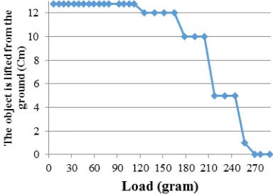
3.1 Robot Arm’s Maximum Payload
The experiment to test maximum payload was done by loading the robot arm with specific weight object and measuring the lifting from the ground. The experiment was done by adding object to the end-effector and increasing its weight gradually. We determine the maximum payload by the weight when robot arm cannot lift the object from the ground (Figure 8). The experiment result is shown
inFigure 9. The data shows that the robot arm can
lift object up to 257.4 gram.
3.2 Maximum Operation Distance
[image:6.612.90.300.186.295.2]The experiment was conducted to find out maximum distance operator can control the robot without any difficulty. We tested the commands responsiveness as well as the visual feedback from the robot and measured the maximum distance. The experiment held in one of the road of Institut Teknologi Sepuluh Nopember (Figure 10) which is wide and quiet enough to minimize interference from traffic, buildings or trees. Visual feedback is measured by measuring the video quality and robot’s respond was observed with responding of the robot to the sending commands. The experiment result is shown in Table 1. The result shows that the maximum distance between operator and the robot is 172m to 236m. Distance above 236m is not recommended for it could lead in safety issues.
Figure 8 How the object height is measured
[image:6.612.106.269.438.530.2]Figure 9 Robot arm’s payload experiment result
Figure 10 Experiment to measure maximum operation
[image:6.612.372.461.463.602.2]3.3 Navigation
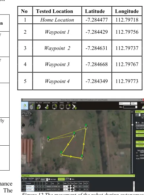
[image:7.612.278.517.104.428.2]The experiment is aimed to test the performance of manual as well as automatic navigation. The manual navigation was performed by user operating it manually using joystick. The robot successfuly passed the rock with maximum size of 12 cm (Figure 11). The automatic navigation was tested by programming the robot to move to several waypoints.
Figure 11 Robot passed the rock
The tested waypoint is shown in Table 2. We sent the waypoints to the robot using Mission Planner software. The movement of the robot during autonomous mode is shown in Figure 12.
Table 2 The tested waypoint
No Tested Location Latitude Longitude
1 Home Location -7.284477 112.79718
2 Waypoint 1 -7.284429 112.79756
3 Waypoint 2 -7.284631 112.79737
4 Waypoint 3 -7.284668 112.79767
5 Waypoint 4 -7.284349 112.79773
Figure 12 The movement of the robot during autonomous mode.
3.4 Object Poses Estimation
The aim of this experiment is to measure the accuracy of the proposed method. We tested the performance of object pose estimation by placing the object in the front of camera. The system obtained the object’s pose and the data is printed to terminal on the Raspberry Pi. The result is compared to the manual measurement. The average accuracy is 92.3%. The comparison of the real object angle and the estimated one is shown in Figure 11. It shows that the method is good enough for estimating the object’s poses.
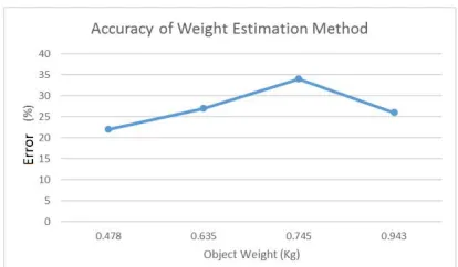
3.5 Object Weight Estimation
[image:7.612.89.294.122.403.2]The aim of this experiment is to measure the accuracy of object’s weight estimation. The experiment result is shown in Figure 14. It shows that the average error is 27.25%.
Table 1 The measurement of maximum operation
distance
Distance (meter)
Robot’s Response
Image from video receiver
Explanation
68 OK Video is clear
135 OK Video is clear
172 OK Gray grains
appear to the video
236 OK Video is poorly
visible.
280 OK There is no
[image:7.612.89.299.508.661.2]Figure 13 Accuracy of Object Poses
Figure 14 Accuracy of Object Weight Estimation Method
4. CONCLUSION
The remotely operated bomb disposal robot equipped with object weight and pose estimations has been successfuly developed and realized. It succeeds to lift object with maximum weight of 257.4 gram. Such ability equal to lift small bomb like C-4 or small IED. The robot’s payload could still possible to be developed while maintaining robot’s dimension. The robot can be operated with maximum distance of 236 meter. To improve radio communication range, the system could be developed further using more advanced antennas. The robot also succeeds to follow the saved waypoints and pass the rock with maximum diameter of 12 Cm. The robot can measure the object weight with accuracy of 27.25% and object poses with average error of 92.3%.
REFERENCES:
[1]Wilson, Clay.Improvised Explosive Devices
(IEDs) in Iraq and Afghanistan: Effects and Countermeasures. s.l. : Congressional Research Service Report for Congress, 2007.
[2] Kemp, John, Gaura, Elena L. and Brusey,
James. Taichung, Using Body Sensor Networks
for Increased Safety in Bomb Disposal Missions. IEEE, 2008. Sensor Networks, Ubiquitous and Trustworthy Computing, 2008. SUTC '08. IEEE International Conference on. pp. 81 - 89. 978-0-7695-3158-8.
[3] Jian-Jun, Zeng, et al, Research on
Semi-automatic Bomb Fetching for an EOD Robot, International Journal of Advanced Robotics Systems, p. 247, 2007.
[4] Luqiao, Fan, Xifan, Yao and Hengnian, An
automatic control system for eod robot based on binocular vision position. Robotics and Biomimetics, 2007. ROBIO 2007. IEEE International Conference on. pp. 914 – 919, 2007.
[5] Zhang, Weijun, Yuan, Jianjun and Li, Jianhua,
The optimization scheme for EOD robot based on supervising control architecture., Robotics and Biomimetics, 2008. ROBIO 2008. IEEE International Conference on . pp. 1421 - 1426 . 978-1-4244-2678-2, 2008
[6] Ryu, Dongseok, et al, Wearable Haptic-based
Multi-modal, Safety, Security and Rescue Robotics, Workshop, 2005 IEEE International. pp. 75-80. 0-7803-8945-x, 2005.
[7]Kron, Alexander, Schmidt, Günther and Petzold,
Bernd, Disposal of explosive ordnances by use
of a bimanual haptic telepresence system, Robotics and Automation, Proceedings. ICRA '04. 2004 IEEE International Conference on. Vol. 2, pp. 1968 - 1973. 0-7803-8232-3, 2004
[8] UNLUTURK, Ali and AYDOGDU, Design and
implementation of a mobile robot used in bomb research and setup disposal, Computers and
Artificial Intelligence (ECAI), 2013
International Conference on. pp. 1 - 5. 978-1-4673-4935-2, 2013
[9] Voth, Danna, A new generation of military
robots, Intelligent Systems, IEEE. pp. 2 - 3. 1541-1672, 2004
[10] Wei, Boyu, Gao, Junyao and Zhu, Jianguo,
Design of a Large Explosive Ordnance Disposal Robot, Intelligent Computation Technology and Automation, 2009. ICICTA '09. Second International Conference on . pp. 403 - 406. 978-0-7695-3804-4, 2009
[11] Carey, Matthew W., Kurz, Eric M. and Matte,
Joshua D. Puerto Vallarta, Novel EOD robot
design with dexterous gripper and intuitive teleoperation, World Automation Congress (WAC), pp. 1 - 6. 978-1-4673-4497-5, 2012
[12]Purwanto, Djoko. Robot Industri dan