-- -- -- --
- - -
-
-
-
-
-----
-
-
---
--- --- --- ---
3270 Information
Display System
Data Stream
---,-
- - -
-
-
-
-
- - -
----
-
-
---_.-
3270 Information
Display System
Data Stream
Programmer's Reference
Fifth Edition (December 1988)
This publication introduces and explains the functions of the 3270 Information Display System data stream. Changes are continually made to the information herein; before using this publication in connection with the operation of IBM systems, refer to the latest IBM System/360 or System 1370 SRL Newsletter for the editions that are applicable and current.
It is possible that this material may contain reference to, or information about, IBM products (machines and programs), programming, or services that are not announced in your country. Such references or
information must not be construed to mean that IBM intends to announce such IBM products, programming, or services in your country.
The names and addresses used in the examples that appear in this manual are fictitious, and any similarity to the names and addresses of actual persons is entirely coincidental.
Publications are not stocked at the address given below; requests for IBM publications should be made to your IBM representative or to the IBM branch office serving your locality.
A form for readers' comments is provided at the back of this publication. Address additional comments to IBM Corporation, Communication Products Information Development, Department E02, PO Box 12195, Research Triangle Park, North Carolina, U.S.A. 27709. IBM may use or distribute any of the information you supply in any way it believes appropriate without incurring any obligation whatever. You may, of course, continue to use the information you supply.
Choosing the Right Book from the 3174 Library
The 3174 library contains information for installing, customizing, operating, maintaining, and programming the data stream for the 3174 control unit. The list below shows the manuals you need to perform these tasks.
To Organize Library Materials:
Binders and Inserts, SBOF-0089 Binder, SX23-0331
Inserts, SX23-0332
To Become Familiar with the 3174:
Master Index, GC30-3515
3270 Information Display System Introduction, GA27-2739
To Prepare Your Site for the 3174:
Site Planning, GA23-0213
Physical Planning Template, GX27-2999
To Set Up and Operate the 3174:
Models 1 L, 1 R, 2R, and 3R User's Guide, GA23-0337 Models 51R, 52R, and 53R User's Guide, GA23-0333 Models 81R and 82R User's Guide, GA23-0313
To Plan for and Customize the 3174:
Customizing Guide, GA23-0214
Central Site Customizing User's Guide, GA23-0342
To Install Features or Convert Models on the 3174:
Encrypt/Decrypt Adapter Customer Installation and Removal Instructions, GA23-0262
Fixed Disk and Diskette Drive Customer Installation and Removal Instructions, GA23-0263
Terminal Multiplexer Adapter Customer Installation and Removal Instructions, GA23-0265
Model Conversion Customer Setup Instructions, GA23-0295
IBM TOken-Ring Network 3270 Gateway Customer Installation and Removal Instructions, GA23-0329
Storage Expansion Feature Customer Installation and Removal Instructions, GA23-0330
Communications Adapter Customer Installation and Removal Instructions, GA27-3830
To Plan for and Use the Asynchronous Emulation Adapter Feature:
Asynchronous Emulation Adapter Introduction, GA23-0331 Terminal User's Reference for Expanded Functions, GA23-0332
To Use the Multiple Logical Terminals Function:
Terminal User's Reference for Expanded Functions, GA23-0332 Customizing Guide, GA23-0214
To Perform Problem Determination:
Customer Extended Problem DetfjJrmination, GA23-0217 Status Codes, GA27-3832
To Obtain Data Stream Programming and Reference Information:
Functional Description, GA23-0218
Data Stream Programmer'sReference, GA23-0059 Character Set Reference, GA27-3831
To Perform Maintenance (Service Personnel):
Models 1L, 1R, 2R, and 3R Maintenance Information, SY27-2572 Models 51R, 52R, and 53R Maintenance Information, SY27-2573 Models 81 Rand 82R Maintenance Information, SY27-2584
To Find Translations of Safety Notices:
Safety Notices, GA27-3824
Preface
Who This Book Is For
This book is for the programmers who need to know what is involved in using the 3270 data stream to produce panels or information at displays and printers.
For those programmers who write the access method macro instructions or other inputloutput (1/0) instructions, this manual is to be used in conjunction with the appropriate access method or ISM program product publications.
This book is also for those programmers who plan and code for support of Systems Application Architecture (SAA). This architecture is supported by the 3270 data stream and this book contains information about the architecture and its relationship to the 3270 data stream.
How This Book Is Organized
This book has twelve chapters and six appendixes:
• Ch'apter 1, "The 3270 Data Stream: Overview and Concepts," introduces the 3270 data stream, gives an overview of it, and discusses 3270 data stream concepts.
• Chapter 2, "Partitions," covers partitions and functions related to partitions, such as INPID, INOP, and PWAIT.
• Chapter 3, "3270 Data Stream Commands," describes the commands used in the 3270 data stream and their operations. Those commands that are necessary for SAA support are designated.
• Chapter 4, "3270 Data Stream Orders and Attributes," describes the orders and attributes used in the 3270 data stream and how they function. It also explains character set properties. Those orders that are necessary for SAA support are designated.
• Chapter 5, "Outbound Structured Fields" lists the outbound structured fields in . alphabetic order, gives their syntax, and describes how they function. It also lists the outbound/inbound structured fields and gives the same information for them. Those outbound structured fields that are necessary for SAA support are designated.
• Chapter 6, "Inbound Structured Fields" lists the inbound structured fields, including query replies, in alphabetic order, gives their syntax, and describes how they function. Those inbound structured fields that are necessary for SAA support are designated.
• Chapter 7, "Magnetic-Reader, Keyboard, and Selector Pen Operations," describes how magnetic readers work with the 3270 data stream, the keyboard functions that affect data stream operation, and the use of the selector pen.
• Chapter 9, "Binary Synchronous Communications (BSC) Environment," discusses a BSC environment and describes the differences in operation from an SNA environment for the 3270 data stream.
• Chapter 10, "Non-SNA Environment (Locally Attached Devices-3272 Version)," discusses a non-SNA environment of locally attached devices (3272 version) and describes the differences in operation from an SNA or BSC environment.
• Chapter 11, "Auxiliary Devices and Work Stations."
• Chapter 12, "Double-Byte Coded Character Set(DBCS) Asia."
• Appendix A, "SNA Sense Codes," summarizes the sense codes returned for data-stream errors.
• Appendix B,"SNA Sense Codes for 3270 Data Stream Structured-Field Errors," summarizes the sense codes returned for structured-field errors.
• Appendix C, "Reset Actions," summarizes the reset actions for the 3270 data stream.
• Appendix 0, "12-,14-, and 16-bit Addressing," explains the addressing used in the 3270 data stream.
• Appendix E, "Special Applications."
• Appendix F, "Functions Supporting Systems Application Architecture (SAA)"
Other Books You
May
Need
The following publications provide a general introduction to the 3270:
• IBM 3270 Information Display System Introduction, GA27-2739
• IBM 3270 Information Display System Library User's Guide, GA23-0058
• IBM 3270 Information Display System C%r and Programmed Symbols, GA33-3056
• IBM 3270 Information Display System 3271 Control Unit
3272 Control Unit 3275 Display Station
Description and Programmer's Guide, GA23-0060
• IBM 3270 Information Display System 3274 Control Unit
Description and Programmer's Guide, GA23-0061
• IBM 3270 Information Display System 3276 Control Unit Display Station
Description and Programmer's Guide, GA 18-2081
• IBM Systems Reference Library
Genera/Information - Binary Synchronous Communications, GA27-3004
• IBM 3278 Display Station Description, GA 18-2127
• IBM 3192 Display Station Description, GA 18-2535
• IBM 3193 Display Station Description, GA 18-2364
• IBM 3179 Color Display Station Description, GA 18-2177
• IBM 3194 Device Functional Interface Programming Guide, SA23-0314
• IBM 3290 Information Panel Description and Reference, GA23-0021
• IBM 3174 Subsystem Control Unit Functional Description, GA23-0218
• IBM Office Information Architectures: Concepts, GC23-0765.
The following publications provide a general introduction to Systems Application Architecture (SAA):
• An Overview, GC26-4341
• Common User Access: Panel Design and User Interaction, SC26-4351
• Writing Applications: A Design Guide, SC26-4362
• Application Generator Reference, SC26-4355
• C Reference, SC26-4353
• COBOL Reference, SC26-4354
• Communications Reference, SC26-4399
• Database Reference, SC26-4348
• Dialog Reference, SC26-4356
• FORTRAN Reference, SC26-4357
• Presentation Reference, SC26-4359
• Procedures Language Reference, SC25-4358
• Query Reference, SC26-4349.
Contents
Chapter 1. The 3270 Data Stream: Overview and Concepts . . . 1-1 Introduction . . . 1-1 Overview .... . . . .. 1-2 Data Stream Format . . . 1-3 Attention Identifiers (AIDs) . . . 1-3 3270 Data Stream Com mands . . . 1-3 3270 Data Stream Orders . . . 1-4 3270 Data Stream Attributes . . . 1-5 Data . . . 1-5 Structured Fields in the 3270 Data Stream . . . 1-5 Concepts . . . 1-5 Unformatted and Formatted Screens . . . 1-5 Kinds of Attributes . . . 1-6 The Cursor . . . " 1-9 Partitions . . . 1-9 Explicit Partitioned and Implicit Partition States . . . 1-10 Read Functions for a Partition . . . 1-10
Chapter 2. Partitions . . . " 2-1 Introduction . . . 2-1 Character Buffer and Concept of Presentation Space . . . 2-1 Presentation Spaces, Windows, and Viewports . . . 2-2 Relationship Between Presentation Space and Viewport . . . 2-3 Scrolling . . . 2-5 The Cursor in Partitions . . . 2-5 Multiple Partitions . . . 2-5 Activate Partition . . . 2-5 The Implicit Partition . . . 2-6 Explicit Partitions . . . 2-6 States and State Transitions . . . 2-7 Partition Wait Condition (PWAIT) . . . 2-9 The System Lock Condition . . . 2-9 The Terminal Wait (TWA IT) Condition . . . , 2-10
Read Operations (SNA) . . . 3-15 Operator Enter Actions . . . 3-15 Application-Initiated Reads . . . 3-15 A Read Partition Structured Field . . . 3-15 A Host Retry . . . .. 3-17 Read States . . . 3-17 Inbound Operation (INOP) . . . 3-19 Inbound Partition Identifier (INPID) . . . 3-20 Enter Actions . . . 3-20 Input Inhibit Conditions . . . 3-20 Enter Inhibit Condition . . . 3-21 Processing of Enter Actions . . . 3-21 Processing of Read Commands (Alphanumeric) . . . 3-22
Chapter 4. 3270 Data Stream Orders and Attributes . . . 4-1 Orders . . . 4-1 Start Field (SF) . . . 4-2 Start Field Extended (SFE) . . . 4-2 Set Buffer Address (SBA) . . . 4-3 Set Attribute (SA) . . . 4 .. 5 Modify Field (MF) . . . 4-6 Insert Cursor (lC) . . . 4-7 Program Tab (PT) . . . 4-7 Repeat to Address (RA) . . . 4-8 Erase Unprotected to Address (EUA) . . . 4-9 Graphic Escape (GE) . . . 4-9 Format Control Orders . . . 4-10 Character Sets . . . 4-10 Nonloadable Character Sets . . . 4-11 Loadable Character Sets
Attributes
4-11 4-11 Field Attributes . . . 4-12 Extended Field Attributes . . . 4-14 Character Attributes . . . 4-15 Conflict Resolution Between Attributes . . . 4-15 Attribute Types and Selection Rules . . . 4-16 Attribute Values and Selection Rules . . . 4-17 Mandatory Fill . . . 4-21 Mandatory Entry . . . 4-22 Trigger . . . 4-23 Processing of Character Attributes . . . 4-26 Defaults for Attributes . . . 4-28
Chapter 5. Outbound Structured Fields . . . 5-1 Introductton . . . 5-1 Outbound Structured Fields . . . 5-2 Outboundllnbound Structured Fields . . . 5-3 Structured Field Grouping . . . 5-3 General Description . . . 5-3 Spanning . . . 5-4 Data Chaining (Non-SNA) . . . 5-5 Structured Field Self-Defining Parameters . . . 5-7 Outbound Structured Fields Only . . . 5-7 Activate Partition . . . 5 .. 8 Begin/End of File . . . 5-9 Create Partition . . . 5 .. 10
Destroy Partition . . . .. 5-14 Erase/Reset . . . . . . .. 5-15 Load Color Table . . . 5-16 Load Li ne Type . . . 5-17 Load Programmed Symbols (Load PS) . . . 5-18 The Compression Function . . . 5-26 Modify Partition . . . 5-34 Outbound Text Header . . . .. 5-36 Outbound Type 1 Text Data Stream . . . 5-38 Outbound 3270DS . . . 5-40 Present Absolute Format . . . 5-42 Present Relative Format
Read Partition
Request Recovery Data . . . . Reset Partition . . . . . . .
5-45 5-47 5-50 5-51 Restart . . . 5-52 SCS Data ... . . . .. 5-53 Select Color Table . . . 5-54 Select Format Group . . . 5-55 Set Checkpoint Interval . . . 5-56 Set MSR Control . . . 5-57 Set Printer Characteristics . . . 5-59 Set Reply Mode . . . 5-61 Set Window Origin . . . 5-63 Outbound/Inbound Structured Fields . . . 5-64
Data Chain 5-65
Destination/Origin . . . .. 5-67 Object Control . . . 5-69 Object Data . . . 5-71 Object Picture . . . 5-73 OEM Data . . . 5-75 Save/Restore Format . . . 5-76 Select IPDS Mode . . . 5-78
Chapter 6. Inbound Structured Fields . . . 6-1 Introduction . . . 6-1 Inbound Structured Fields . . . 6-1 Exception/Status . . . " 6-3
Query Reply (DDM) . . . 6-37 Query Reply (Device Characteristics) . . . 6-39 Set Print Density (SPD) Descriptor . . . 6-40 Horizontal Dimensional Parameters Descriptor . . . 6-41 Vertical Dimensional Parameters Descriptor . . . 6-42 Page Presentation Media (PPM) Descriptor . . . - . . . 6-42 Set Text Orientation (STO) Descriptor . . . .. 6-46 Query Reply (Document Interchange Architecture (DIA» . . . 6-47 Self-Defining Parameters . . . 6-48 Query Reply (Field Outlining) . . . 6-49 Query Reply (Extended Drawing Routine) . . . 6-51 Query Reply (Field Validation) . . . 6-52 Query Reply (Format Presentation) . . . 6-53 Query Reply (Graphic Color) . . . 6-54 Query Reply (Graphic Symbol Sets) . . . 6-55 Query Reply (Highlight) . . . 6-56 Query Reply (Image) . . . 6-58 Query Reply (Implicit Partition) . . . 6-59 Query Reply (IOCA Auxiliary Device) . . . 6-63 Query Reply (Li ne Type) . . . 6-65 Query Reply (MSR Control) . . . 6-66 Query Reply (Null) . . . 6-67 Query Reply (OEM Auxiliary Device) . . . 6-68 Direct Access Self-Defining Parameter . . . 6-69 Query Reply (Paper Feed Techniques) . . . 6-70 Query Reply (Port) . . . 6-72 Query Reply (Procedure) . . . 6-73 Query Reply (Reply Modes) . . . 6-74 Query Reply (RPQ NAMES) . . . 6-75 Query Reply (Save/Restore Format) . . . 6-76 Query Reply (Segment) . . . 6-77 Query Reply (Settable Printer Characteristics) . . . 6-78 Query Reply (Storage Pools) . . . 6-79 Self-Defining Parameters . . . 6-79 Query Reply (Summary) . . . 6-81 Query Reply (Text Partitions) . . . 6-82 Query Reply (Transparency) . . . 6-84 Query Reply (Usable Area) . . . 6-85 On pels Limit Self-Defining Parameter . . . 6-90 Multiple Usable Area Self-Defining Parameter . . . 6-91 Alternate Usable Area Self-Defining Parameter . . . 6-93 Query Reply (3270IPDS) . . . 6-95
Chapter 7. Magnetic-Reader, Keyboard, and Selector Pen Operations . . . 7-1 Magnetic-Reader Operations . . . 7-1 3275/3277-Compatible Operation . . . 7-1 Numeric/Alphanumeric Operation . . . 7-6 Stripe Codes and Application Program Codes . . . 7-6 Secure/Nonsecure Magnetic-Stripe Cards . . . . . . .. 7-10 Test Card . . . 7 -11 Keyboard Functions . . . 7-11 Keys·that Affect the Data Stream . . . 7-11 Clear Partition . . . 7-14 Clear . . . 7-14 Keyboard Actions with Attribute Selection Keys . . . 7-15 Keyboard Actions in Partitions . . . 7-15
Scrolling Partitions . . . 7-16 Selector Pen Operation . . . 7-18 Selector Pen Field Format . . . 7-18 Designator Characters . . . 7-18 Selecting Fields in Partitions . . . .. 7-19
Chapter 8. Printer Considerations . . . .. 8-1 Printers . . . 8-1 Local-Copy Function in an SNA Environment . . . . . . .. 8-3 Copy Initiation . . . 8-3 Printer Availability . . . 8-4 Display/Printer Compatibility . . . 8-5 APL Mismatch . . . 8-5 Character Attribute/Extended Field Attribute (CA/EFA) Mismatch . . . 8-6 Programmed Symbols (PS) Considerations . . . 8-6 Extended Color Mismatch . . . .. 8-6 Extended Highlighting Mismatch . . . 8-6 Partition Mode Considerations . . . 8-6 Local-Copy Command in the BSC Environment . . . 8-7 I PDS Data/Non-SNA . . . 8-9 IPDS Selection . . . 8-10 Local Copy ... . . . .. 8-11 Pacing . . . 8-11 Input Transmissions . . . 8-11
Chapter 9. Binary Synchronous Communications (BSC) Environment . . . 9-1 Transparent Mode . . . 9-1 Write Commands . . . 9-1 Read Commands . . . 9-2
Read Buffer Command . . . .. 9-2 Read Modified Command . . . 9-2 Test Request Read . . . 9-3 Inbound Transmissions . . . 9-3 Inbound Operation (INOP) . . . 9-4 Read States . . . 9-4
Normal Read State
Data Pending States . . . . Read-State Transitions . . . . Retry States . . . . . . . Indicators . . . . Host Acknowledgments . . . . Processing of Read Commands . . . . Processing of Read Partition Query Structured Fields . . . . BSC Copy Command . . . .
Chapter 10. Non-SNA Environment (Locally Attached Devices-3272 Version) Commands . . . .
Host Acknowledgments . . . : . . . 12-3 Processing of Read Commands . . . 12-4 Processing of Read Partition Query Structured Fields . . . 12-5
Chapter 11. Auxiliary Devices and Workstations . . . 12-5 Introduction . . . 12-5 Data Routing . . . 12-5 Query Reply . . . 12-5 Input Control . . . 12-5 Auxiliary Device and Display Interaction . . . 12-5 Exception Handling . . . 12-6
Chapter 12. Double-Byte Coded Character Set (DBCS) Asia . . . 12-6 Introduction .... , . . . 12-6 Codepoints . . . 12-7 Graphic Codes . . . ; . . . 12-7 Two-Byte Coded Field Selection Designators . . . .. 12-8 Two-Byte Coded Pri nter and Control Characters . . . 12-8 DBCS Fields . . . 12-8 Character Set Attribute Type and Values . . . 12-9 Data Stream Processi ng . . . . . . .. .... 12-9 Operator Interface . . . 12-11 DBCS Character Attri bute (SA) . . . 12-12 Shift Out (SO)/Shift In (SI) . . . 12-12 Referenci ng the Character Set . . . 12-12 Exception Conditions For SO/SI . . . . Set Attribute (SA) Order and SO/SI Interaction . . . . SO/SI Creation by Operator . . . . Types of Field . . . .
12-12 12-13 12-13 12-13 Graphic Character Input . . . A-1 Orders . . . E-2
Appendix A. SNA Sense Codes for 3270 Data Stream Commands and Orders X-1
Appendix B. SNA Sense Codes for 3270 Data Stream Structured-Field Errors X-3
Appendix C. Reset Actions . . . X-9
Appendix D. 12-,14-, and 16-Bit Addressing . . . D-1
Appendix E. Special Applications . . . E-1 Query Reply (Anomaly Implementation) . . . E-1 3270 PC Application-to-Application . . . E-2
Appendix F. Functions Required for Systems Application Architecture (SAA) Support . . . F-1
Query Replies . . . F-1 Structured Fields . . . F-1 Basic 3270 Commands . . . F-1 Basic 3270 Orders . . . F-2 3270 Controls/Special Characters . . . F-2
List of Abbreviations . . . X-1
Glossary . . . X-3
Figures
Tables
1-1. Mapping the Display to the Character Buffer . . . .. 1-2 1-2. Example of Formatted Fields . . . 1-6 1-3. Character and Extended Field Attributes-A Conceptual View 1-6 2-1. Presentation Space and Viewport (without Scrolling) . . . 2~2
2-2. The Presentation Plane-A Conceptual View . . . 2-3 2-3. Presentation Space, Window, and Viewport (with Scrolling) . . . 2-4 2-4. Management of Presentation Spaces .. . . .. 2-8 3-1. Read-State Transitions . . . 3-19 5-1. Structured-Field Format . . . 5-1 5-2. Vertical and Horizontal Slicing of a Character Cell .. I . . . . . 5-27
5-3. Type 1 Data Format - An Example Dot Pattern Encoded . . . 5-28 5-4. Example of Compression Algorithm Using Comparison Rule 1 5-31 5-5. Example of Compression Algorithm Using Comparison Rule 2 5-32 5-6. Example of Compression Algorithm Using Comparison Rule 3 5-33 6-1. Diagram of steps used in interpreting Load PS Sets data stream. 6-27 7-1. Display Screen Activity before and after Magnetic-Stripe Input
(Unformatted Display) . . . 7-3 7-2. Display Screen Activity before and after Magnetic-Stripe Input
(Formatted Display with Unprotected Field Attribute) . . . 7-4 7-3. Display Screen Activity before and after Magnetic-Stripe Input
(Formatted Display with Protected Field Attribute) . . . 7-5 8-1. The Copy Data Stream . . . 8-8 0-1. Conversion of Binary Values to Hexadecimal Values That Obtain
Graphic Symbols . . . 0-2
1-1. Attribute Pairs . . . 1-8 3-1. Command codes and abbreviations . . . .. 3-2 3-2. Write Control Character (WCC) Bit Definitions for Displays . . . 3-3 3-3. Write Control Character (WCC) Reset Actions (for Displays) . . . 3-4 3-4. Attention Identification (AID) Bytes Sent from the Display to the
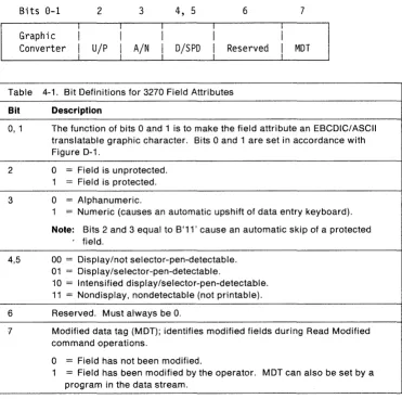
Application Program . . . 3-9 4-1. Bit Definitions for 3270 Field Attributes . . . 4-1,3 4-2. Attribute Default Conditions . . . 4-28 8-1. The WCC Byte (As Defined for Use with Printers) . . . 8-1 8-2. Copy Control Character (CCC) . . . 8-9 9-1. Read-State Transitions for BSC . . . 9-5 10-1.
A-1. B-1. C-1.
Read-State Transitions for Non-SNA Locally Attached Devices-3272 Version . . . . SNA Sense Codes for 3270 Data Stream Command and Order Errors SNA Sense Codes for Structured-field Errors
Reset Actions
Summary of Changes
This revision incorporates the following new information:
• Outbound Structured fields
Begin/End of File Load Color Table
Load Programmed Symbols Request Recovery Data Restart
Select Color Table
Set Printer Characteristics
• Inbound Structured fields
Query Replies
Query Reply (Character Sets)
Query Reply (Cooperative Processing Requestor) Query Reply (Data Chaining)
Query Reply (Data Streams) Query Reply (DBCS-Asia)
Query Reply (Device Characteristics)
Query Reply (Settable Printer Characteristics) Query Reply (Text Partitions)
Query Reply (Transparency) Query Reply (Usable Area)
In addition to the above, the following functions that enable 3270 Data Stream support for Systems Application Architecture are included:
• Query Replies
Query Reply (Character Sets) Query Reply (Implicit Partition) Query Reply (Null)
Query Reply (Summary) Query Reply (Usable Area)
• Structured Fields
Read Partition Erase/Reset Outbound 3270DS.
• Basic 3270 Commands
Erase All Unprotected (EAU) Erase/Write
Erase/Write Alternate Read Buffer
Read Modified Read Modified All Write
• Basic 3270 Orders
Start Field
Set Buffer Address Program Tab Insert Cursor Repeat to Address
Erase Unprotected to Address
• 3270 Controls/Special Characters.
Changes are indicated by a vertical line to the Jeft of the changed text.
Chapter 1. The 3270 Data Stream: Overview and Concepts
Introduction
This chapter introduces the 3270 data stream, gives an overview of what it is and what it does, and discusses data stream concepts. This manual describes all 3270 data stream functions that are implemented at the time of publication. However, just because this manual describes a function does not mean that your particular device implements that particular function. Consult your product library for the 3270 data stream functions implemented by your products.
The 3270 data stream is a formatted data stream used for transmitting data between an application program and a terminal. The 3270 data stream supports both display and printer functions. The SNA format is:
LH
I
TH
I
RH
I
3270 Data Stream
I
LT
The LH, TH, RH, and LT are the link header, transmission header,
Overview
The 3270 data stream is based upon the presence of a mapped character buffer in the device. There is a fixed one-to-one relationship between each character storage location in the buffer and each character position on the display. For example, if the display surface consists of 12 rows and SO columns, row 1 maps to the first 80 character storage positions in the character buffer, row 2 maps to the second 80 character storage positions, and so on. The sequence is the same regardless of the size of the display. (See Figure 1-1.)
0 79
80 159
160 239
240 319
320 399
400 479
480 559
560 639
640 719
720 799
800 879
880 959
80-Character-per-Line Display
0
1
2
·
·
·
·
959
960-Byte
Character Buffer
Figure 1-1. Mapping the Display to the Character Buffer
The data stream controls the processing and formatting of data with commands, orders, control characters, attributes, or structured fields. The command byte defines the function to be performed by the display.
The data stream allows the application program to divide the display surface into several areas, one of which will be an active area. Each area is related to a partition, and the partition that is active is the one that the operator is using to enter data or requests.
The character buffer may contain codes for graphic characters or field attributes. Because each storage location in the character buffer is mapped to a position on the display screen, the field attribute takes up a character position on the display screen. The 3270 field attribute defines a field as that field attribute position plus the character positions up to, but not including, the next field attribute in the character buffer.
Warning: Installation of the Country Extended Code Page (CECP) RPQ may cause a loss of data integrity in databases and applications. Please read the IBM 3174 Functional Description, GA23-021S.
Data Stream Format
An application program sends data (and control instructions) to the display by means of commands. An outbound data stream is a data stream sent from the application program to the device, and contains:
Command
wce
Data
OR
Structured Field
Structured Field
The write control character (WCC) is used with write type commands only. (WSF in the example above stands for Write Structured Field, a command that is explained later in this book.)
An inbound data stream is sent from the device to the application program and consists of an attention identifier (AID) followed by data. An inbound data stream may also consist of an AID (X'88') followed by structured fields.
AID
Cursor Address
Data
(2 bytes)
OR
AID
(X'88')
Structured Fields
In many cases the data is optional.
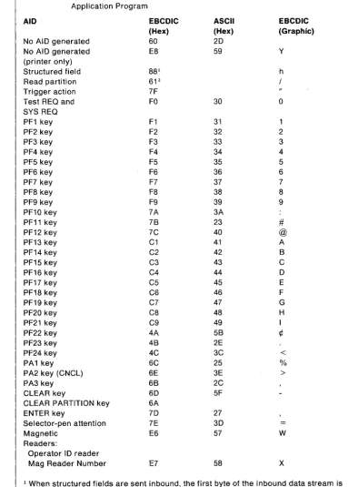
Attention Identifiers (AIDs)
An AID, which is always the first byte of an inbound data stream, describes the action that caused the inbound data stream to be transmitted.
3270 Data Stream Commands
An application program sends data (and control characters) to th~ display by means of commands. Thecommands and data used by theapplication program and display are as follows:
Command Data after Command Can Include:
Write A WCC, orders and data Erase/Write A wee, orders and data Erase/Write Alternate A wee, orders and data Erase All Unprotected None
Read Modified None Read Modified All None Read Buffer None
Write Structured Field Structured fields
In the 3270 data stream, some write commands are followed by a control character, the write control character (WeC). The wce is used to perform such functions as sounding the audible alarm, formatting the printer, and restoring or enabling the keyboard.
3270 Data Stream Orders
Orders are instructions in the 3270 data stream that provide control information. The orders that can be sent with the write commands are:
• Set Buffer Address (SBA)
• Start Field (SF)
• Start Field Extended (SFE)
• Modify Field (MF)
• Set Attribute (SA)
• Insert Cursor (Ie)
• Program Tab (PT)
• Repeat to Address (RA)
• Erase Unprotected to Address (EUA)
• Graphic Escape (GE).
The orders that can be included in the inbound data stream are:
• Set Buffer Address
• Start Field
• Start Field Extended
• Set Attri bute
• Graphic Escape.
3270 Data Stream Attributes
Data
Attributes determine the properties of a field or of characters within a field. The display uses three kinds of attributes: field attributes, extended field attributes, and character attributes.
Data is the information transferred between the application program and the display. It may be used or acted upon by either the application program or the operator, or by both.
Structured Fields in the 3270 Data Stream
Concepts
Structured fields are used to convey additional control functions and data to or from the terminal. The Write Structured Field (WSF) command is used to transmit structured fields outbound. There are three types of structured fields: outbound, outbound/inbound, and inbound. The outbound and the outbound/inbound structured fields are defined in Chapter 5, "Outbound Structured Fields."
An AID (X'88') indicates inbound structured fields. The inbound structured field functions that can be sent by the display are defined in Chapter 6, "Inbound Structured Fields."
The display shows data that has been transmitted to it from an application program or data that has been entered by the operator. The displayed data can be modified or deleted by the operator (or by further transmissions from the application
program), and the revised data can be transmitted back to the application program for storage or additional processing.
Data received from the application program, or data to be transmitted to the application program, is stored in a buffer and is displayed on the screen in the form of alphanumeric characters and symbols. The displayed data is updated when the buffer data is modified by the operator and when new data is received from the application program.
Unformatted and Formatted Screens
An application program can use either a formatted or an unformatted screen to communicate with a display operator:
• A formatted screen is organized into fields by the application program. Fields are defined by the field or extended field attributes.
• An unformatted screen is regarded as one with a storage and display area that the operator uses in free-form manner. There are no fields defined.
[~JNAME
:CJJOHN B DOE
CJJOB TITLE :CJ WRITER
[image:27.620.33.557.28.759.2] [image:27.620.78.546.491.722.2][~lPHONE
#:[=1383-7628
Figure 1-2. Example of Formatted Fields
Kinds of Attributes
Field ·Attributes
Three kinds of attributes are used in the 3270 data stream: field attributes, extended field attributes, and character attributes. Field and extended field attributes define the start of a field and control the characteristics of the field. Character attributes control the characteristics of a character.
The field attribute occupies a character location in the character buffer and is stored in such a way that it is always displayed as a blank. The extended field attributes and character attributes do not occupy positions in the character buffer', but are nevertheless stored and do control the characteristics of the field and characters, respectively.
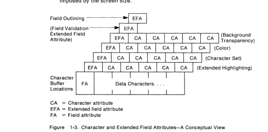
Conceptually, the extended field attributes are extensions of the field attribute, as shown in Figure 1-3.
The field attribute is defined by the application program for the following purposes:
• To define the start of a field. A field consists of the field attribute and all the data following it, up to (but not including) the next field attribute. A field can wrap (continue) from the end of one row to the beginning of the next row within the presentation space. A field can also wrap from the last location in the presentation space to the first location. In any case, the field is terminated by the next field attribute.
There is no limit to the number of fields that can be defined, other than that imposed by the screen size.
Field Outlining
(Field Validation Extended Field
Attribute) ,.---L----r_'---.---L_..--...I..----.._.l----,----L_..,.----I T r a ns pa re ncy) (Background
Character
Buffer FA Data Characters .... Locations
CA
=
Character attribute EFA=
Extended field attribute FA=
Field attribute(Color)
Figure 1-3. Character and Extended Field Attributes-A Conceptual View
• The 3270 field attribute defines the following field characteristics:
Protected or Unprotected. A protected field is protected from modification by the operator. An unprotected field is available for the operator to enter or modify data. The unprotected definition classifies a field as an input field.
Alphanumeric or Numeric. Subject to its being unprotected, an alphanumeric field is one into which an operator enters data normally, using the shift keys (uppercase/lowercase or numeric/alphabetic) as required.
Fields defined as numeric will accept all uppercase symbols and numerics from a data entry-type keyboard. On a typewriter-type keyboard, numeric has no meaning and all entries are accepted.
Autoskip. A field defined as protected and numeric that causes the cursor to skip over this field.
Nondisplay or Display/Intensified Display. The selected characteristics apply to the entire field. Nondisplay means that any characters entered from the keyboard are entered into the buffer for possible subsequent transmission to the application program but they are not displayed. Intensified display means the intensified characters appear on the screen brighter than the nonintensified characters. Some devices may not be able to intensify characters on the screen and will therefore highlight in a different manner.
Detectable or Nondetectable. A field defined as detectable can be detected by the selector pen or the cursor select key, subject to the use of a
designator character.
Base color (four colors) can be produced on color displays and color printers from current 3270 application programs by use of combinations of the field intensify and field protection attribute bits. For more information on color, refer to IBM 3270 Information System: Color and Programmed Symbols, GA33-3056.
Extended Field Attributes
The extended field attribute provides additional field definition beyond that provided by the field attribute. The extended field attribute defines field characteristics such as color, character set, field validation, field outlining, and extended highlighting. The extended field attribute is always associated with a field attribute. (See Figure 1-3 on page 1-6)
Character Attributes
A character attribute is associated with an individual character to define characteristics such as character color, character highlighting, or character set. The extended field attributes of any single character are superseded by the character attributes associated with it. However, characters in nondisplay fields are never displayed. The attribute structure used for character attributes is the same as for extended field attributes. (See Table 1-1.)
The attribute structure used for extended field attributes defines all characteristics with attribute type-value pairs, as shown in Table 1-1. Each attribute type has associated with it a set of attribute values.
Table 1-1 (Page 1 of 2). Attribute Pairs
Attribute Type
Extended highlighting
Color
Character set
Field validation
Attribute Value
Default-If used as a character attribute, the default is the characteristics defined by the extended field attribute. If used as an extended field attribute, the default
becomes those characteristics indicated by the Query Reply (Highlight) structured field.
Underscore-Each character or field is underlined.
Blink-Each character or field affected is caused to flash on and off.
Reverse Video-In each character cell affected, the on/off illumination state every display point is reversed. The effect is analogous to white on black becoming black on white.
Default-If used as a character attribute, it assumes the characteristics of the extended field attribute. If used as an extended field attribute, it is indicated by the Query Reply (Color) structured field. Multicolor-Indicates that the color is defined by a triple-plane Programmed Symbol set.
All others-Assigned to the color identifications as indicated by the Query Reply (Color) structured field.
Default-If used as a character attribute, it assumes the characteristics of the extended field attribute. If used as an extended field attribute, it is the
nonloadable character set that has the LCID of X'OO' in the Query Reply (character sets) structured field.
Local Character Set ID-For the loadable or nonloadable character set.
Mandatory Entry-'-A field that must be modified by the operator before the operator can transmit any data from the display.
Mandatory Fill-A field that, if modified by the operator, must be filled with characters other than the null character before the operator can move the cursor out of the field or transmit any data from the display.
Trigger-A field that, if modified by the operator, is transmitted inbound as soon as the operator tries to move the cursor out of the field. This allows the application program to receive and to validate fields one by one.
[image:29.615.74.496.64.732.2]The Cursor
Partitions
Table 1-1 (Page 2 of 2). Attribute Pairs
Attribute Type
Field outlining
Transparency
Attribute Value
Default-No fields outlined.
Outlining-Sixteen kinds of outlining can be defined by the combinations of the four horizontal and vertical lines.
Default-If used as a character attribute, it assumes the characteristics of the extended field attribute. If used as an extended field attribute, the default is determined by whatever the device
supports on its inbound response to a query reply.
Transparent-Picture elements (pels) of character background are ignored: underlying presentation space can be viewed.
Opaque-Pels set as indicated. Underlying presentation space cannot be viewed.
The cursor is a special mark that is displayed on the screen to indicate where the next action from the keyboard will take effect (for example, where the next character keyed in will appear on the screen).
The cursor can be moved by the operator or by instructions from the application program.
A character entered at the keyboard is stored in the display buffer (and is displayed) at the cursor position. Then the cursor advances one position and is ready for the next character to be entered. In order to enter a character, the cursor must be positioned in an unprotected field. If a character already exists at the current cursor position, then (except in insert mode) that character is overwritten by the entered character.
If the display supports partitioning (see Chapter 2, "Partitions" for more
information on partitions), the application program can define a logical area called a partition that may differ in both size and shape from the physical display screen. The partition is defined by use of the Create Partition structured field. (Structured fields are discussed in Chapter 5, "Outbound Structured Fields" and
[image:30.615.148.488.60.326.2]Explicit Partitioned and Implicit Partition States
The 3270 data stream supports displays in both explicit partitioned and im plicit partition states. The initial state of a display supporting partitions is the implicit partition state (for example, power-on reset). Interaction with implicit partition 0 on a display that supports partitioning is the same as on a display that does not support partitioning.
The application program can replace the implicitly created partition by explicitly creating one
or
more partitions of its own, thereby placing the display in explicit . partitioned state.The display may b~ returned to implicit partition state from explicit partitioned state by sending an Erase/Write or Erase/Write Alternate command with bit 1 of the
wee
set equal to 1.Read Functions for a Partition
The transmission of data from a partition can be initiated either by the application program or by the display operator the same as for a nonpartitioned display surface. The display operator, however, can initiate a transmission only from an active partition. The application program can initiate
a
transmission from any partition by using the Read Partition structured field.The Read Partition structured field provides the same read functions for partitions as the read commands do for nonpartitioned screens, for example, Read Modified and Read Buffer.
Chapter 2. Partitions
Introduction
Partitioning allows the application program to define a presentation space that may be different in both size and shape from the physical display screen. Multiple partitions can be defined for the display that will allow the display screen to be divided into several rectangular areas called viewports, where data from multiple partitions may be displayed on the same physical display screen. The viewport is the area used to display and enter data for its partition. (See Figure 2-1 on page 2-2.)
The application program can organize a partition as either formatted or unformatted.
Each partition has a unique partition identifier (PIO) assigned at creation time. The PIO identifies the partition so that the application program can send data to, or receive data from, individual partitions.
Similarly, the operator can enter, delete, or modify data in any selected partition (except in protected fields) by positioning the cursor appropriately within the partition's viewport.
If the application program does not define any partitions, the device assumes a single partition of default size with the PIO equal to O. This is referred to as the implicit partition.
Character Buffer and Concept of Presentation Space
The amount of storage in the character buffer that is used by the partition is defined by the application program. Oata in this buffer may be interacted with by the application program and by the operator. The character blJffer provides
Screen
Viewports for Other Partitions
Viewport on Screen
Figure 2-1. Presentation Space and Viewport (without Scrolling)
Conceptually, however, a partition can be regarded as a two-dimensional
presentation space whose size is defined in terms of its depth H (number of rows) and its width W (number of columns). Thus, the character buffer associated with this partition is defi ned to be WxH bytes. The addresses of the character buffer locations range from 0 to (W x H) -1.
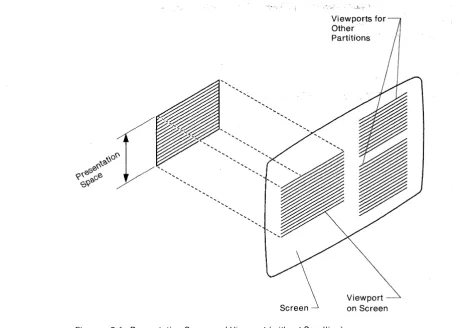
Presentation Spaces, Windows, and Viewports
A partition has associated with it a conceptual two-dimensional surface, called the presentation space. Data may be thought of as being presented on this
two-dimensional surface, although the surface does not exist physically as such on the device. (See Figure 2-2 on page 2-3.) A window on the presentation space identifies that part of the presentation space available for viewing on the display surface.
[image:33.615.95.559.56.384.2]Column 1
~
Row 1--'"Presentation Space
"'--Row H
i
Column W
Figure 2-2. The Presentation Plane-A Conceptual View
The viewport is that area on the display surface where the terminal operator sees the area of the presentation space bounded by the window. Each viewport is related to a window so that the area of the presentation space within the window appears on the screen within the viewport. The combination of the viewport and associated presentation space is a partition. (See Figure 2-2.)
For processing 3270 data streams, a coordinate system must be defined on the presentation space. Rather than formatting data on the presentation space in row/column coordinates, 3270 compatibility requires lineal addressing of the presentation space (the character buffer) by use of the 3270 Set Buffer Address order. (Orders are discussed in Chapter 4, "3270 Data Stream Orders and Attri butes.")
Relationship Between Presentation Space and Viewport
When the display function scrolling is not implemented, a partition's presentation space and viewport have the same dimensions. (See Figure 2-1.) Assuming it is not in a nondisplay field, each data character in the presentation space is
displayed in the corresponding row and column of the viewport.
When the presentation space is larger than the viewport, the viewport displays the data from the window. (See Figure 2-3 on page 2-4.) The window and the viewport have the same dimensions (rows and columns). Assuming it is not in a nondisplay field, each data character in the window is displayed in the
2-4
L
Presentation Space Scrolled Fully Up ce Scrolled Fully DownI
Presentation SpaViewports for Other Partitions
Screen
Viewport on Screen
Viewports for Other Partitions
Viewport
V
Screen on ScreenFigure 2-3, Presentation Space, Window, an d Viewport (WI 'th Scroll i ng)
[image:35.617.53.540.49.684.2]Scrolling
In a scrollable partition, the presentation space data can be viewed by:
• The operator using the keys for scrolling • The application program.
With this function, the application program positions the 'window by specifying the number of rows (see "Set Window Origin" in Chapter 5) by which the top of the window is to be offset from the top of the presentation space.
The Cursor in Partitions
As on the nonpartitioned screen, the cursor can be moved by operator keystrokes or by instructions from the application program; but, always, the range of cursor movement on the screen is constrained to the bounds of a viewport. The cursor can be moved out of a given viewport only into another viewport; this can be accomplished, for example, by means of the jump-partition key or an Activate Partition structured field sent from the application program. The cursor can never appear at a screen position that is outside the bounds of a viewport. The partition associated with the viewport that contains the cursor is known as the active partition. The operator can enter data only into the active partition.
Associated with each partition is a current cursor position on the presentation space that determines where alphanumeric data is placed in the presentation space during operator keystroking. The cursor on the display screen is displayed at the current cursor position of the active partition's presentation space. Data entry or cursor movement causes the current cursor position of the partition to be changed.
Multiple Partitions
The physical screen can be divided into several viewports, allowing data from multiple partitions to be displayed on the same physical screen. The partition with which the operator interacts is called the active partition, and only one partition may be active at a time. Each partition is identified by a partition identifier (PID).
The operator may cause the screen cursor to jump from one partition to the next by preSSing the designated jump-partition key. PreSSing this key moves the cursor to the current cursor position of the next partition and makes that partition the active partition. If the partition ID has the value N, the next active partition is that partition with the smallest PID greater than N. If no such partition exists, the next active partition is that partition with the lowest PID.
Activate Partition
The application program may activate any partition by using the Activate Partition structured field and may deactivate any partition by activating another partition. The host application program may destroy any partition by using the Destroy Partition structured field. (These structured fields are described in
The Implicit Partition
The display is placed in implicit partition state at BIND time (SNA) or when the display is powered on (non-SNA). A single implicitly defined partition is created automatically and assigned a PIO of 0 with the default screen size. In implicit partition state, the size of the implicit partition is controlled by the Erase/Write (EW) and Erase/Write Alternate (EWA) commands in the data stream.
EW redefines implicit partition 0 with the default screen size. EWA redefines implicit partition 0 with the alternate screen size. The default and the alternate size are specified in BIND SESSION.
The characteristics of the implicit partition are as follows:
• Partition parameters expressed in row/column coordinate system
• Partition size
=
Screen size• Window size
=
Partition size• Viewport size
=
Window size • Viewport origin=
Screen origin• No scrolling permitted
• Unprotected (operator interaction allowed).
Note: For non-SNA envi ronments, the default size is the largest 3277 size that fits on the display screen. The alternate size is implementation defined.
Explicit Partitions
The Create Partition structured field is used to replace the implicitly created partition 0 with a partition that is explicitly defined. The fi rst Create Partition causes the implicit partition to be destroyed and the display to be placed in an expl icit partitioned state.
The difference between the implicit partition, hereafter called implicit partition 0, and explicit partition 0 is that implicit partition 0 is assigned partition
characteristics by default, whereas the application program can specify partition characteristics for explicit partition 0 by using the Create Partition structured field. In addition, implicit partition 0 operates in implicit partition state, while explicit partition 0 operates in explicit partitioned state.
No m'atter which partition 0 is used, commands can be sent to the partition as the first byte of the data stream or enclosed in a structured field. When data is returned from either implicit or explicit partition 0, it is transmitted without use of the Inbound 327008 structured field.
States and State Transitions
Displays using the 3270 data stream can operate in one of two states. When operating without partitions (operating with implicit partition 0), the device is said to be in implicit partition state. When partitions have been created explicitly, with the Create Partition structured field, the device is said to' be in the explicit
partitioned state. In each state, all the orders and commands described in this manual are valid. The distinction between the two states relates to the way in which the usable area is managed. In implicit partition state, the size of the viewport equals the screen size. In explicit partitioned state, there can be more than one viewport on the usable area. For more information, see the Create Partition structured field in Chapter 5, "Outbound Structured Fields."
The presentation space controls the value at which buffer addresses wrap. For those devices that permit scrolling, the presentation space may be larger than the viewport. For devices that do not permit scrolling, the presentation space is the same size as the viewport.
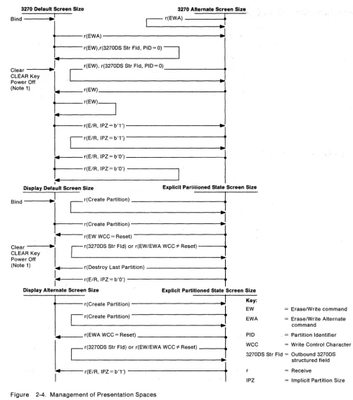
The management of presentation spaces is summarized in Figure 2-4 on page 2-8. The commands, reset function, and structured fields shown in this figure are described in detail in the manual.
When in implicit partition state, EW establishes a default screen size and EWA establ ishes an alternate screen size.
3270 Default Screen Size 3270 Alternate Screen Size
Bind
~I
Cr(EWA)f
Lr(EWA)---"---.~
rr(EW),r(3270DS Sir Fld,
PID~O) ~
,4r(EW), r(32700S Str Fld, PIO=O) _ _ _ _ _ _ _ _ ... Clear ----t~.
r
CLEAR Key 1
~
Power Off
"'1
(Note 1) .. r(EW) _ _ _ _ _ _ _ _ _ _ _ _ _ _ _ _ -f_
t--r(EW)~
tc
r(E/R'IPZ=b'1')~t
C
r( E / R , I P Z = b ' 1 ' ) - - - . . ."'1
.. r ( E / R , I P Z = b ' O ' ) - - - -....
-f--r(E/R,IPZ~b'O')
- - - ,14
Display Default Screen Size Explicit Partitioned State Screen Size
Bind - - - - i ..
~j
Cr(Creale Partillon)---~-1f
.
r(Create Partition) ---~-J
," r(EW WCC= Reset) Clear - - - - 1 ...
1
r.
r(32700S Str Fld) or r(EW/EWA WCC* Reset) CLEAR KeyL
Power Off ..
(Note 1) .. r(Oestroy Last Partition)
---.i
1 ... - - - - -r(E/R, IPZ = b'O') . .
-I
Display Alternate Screen Size Explicit Partitioned State Screen Size
..----r(Create Partition)
---i~~1
J
[image:39.620.44.547.63.632.2]C
r(Create Partition)... .--_ _ _ r(EWA WCC = Reset) _ _ _ _ _ _ _ _ _ _ _ _ ..
C
r(32700S Str Fld) or r(EW/EWA WCC =F Reset)... ,4t----
r(E/R, IPZ = b'1')---~-..t
Figure 2-4. Management of Presentation Spaces
Notes:
Key: EW EWA
PIO
= Erase/Write command = Erase/Write Alternate
command
. = Partition Identifier WCC = Write Control Character 32700S Str Fld = Outbound 32700S
structured field = Receive
IPZ = Implicit Partition Size
1. Any local action that resets the screen, such as device return from local-test or SSCP use, may also reset the screen size to the default value.
2. If a structured field cannot be processed because of a data stream error, no state transition occurs.
Partition Wait Condition (PWAIT)
The partition-wait condition (PWAIT) is a partition-related input-inhibit condition that, when activated, prevents operator keystroking into that partition. PWAIT is set by any operator enter action except a trigger action. The following rules apply:
• PWAIT is only reset by the host by acknowledging the INOP.
• While the PWAIT condition is active for the active partition, the appropriate indicator is displayed. The operator can use the jump-partition key to jump to another partition and keystroke into that partition. The PWAIT indicator will be removed from the screen, but the PWAIT condition will be remembered, and when the original partition becomes active again the PWAIT indicator will again be displayed.
• The PWAIT condition can only be applied against INPIO.
The System Lock Condition
System Lock is a partition-related input-inhibit condition that, when activated, prevents operator keystroking into that partition. The following rules apply:
• System Lock can be reset by the host or by the operator.
• W~ile System Lock is active for the active partition, an appropriate indicator is displayed (provided a higher-priority condition, such as PWAIT, does not exist). The operator can use the jump-partition key to jump to another partition and keystroke into that partition. The System Lock indicator will be removed from the screen, but the System Lock condition will be remembered, and when the original partition becomes active again the System Lock indicator will again be displayed.
• At anyone time, several partitions can have a system-lock condition.
• System Lock is activated, together with PWAIT, by any operator enter action except a trigger action. If the display is in CONTENTION state, 81D or begin bracket (88) will activate System Lock on partition 0 if partition 0 is active.
• System Lock is removed by any of the following:
A write with keyboard restore removes System Lock from the partition addressed by the write.
A RESET key pressed by the operator removes System Lock from the active partition.
The Terminal Wait (TWAIT) Condition
TWAIT is a terminal-related input-inhibit condition that prevents the operator from keystroking. TWAIT is activated when there is only one partition and the operator performs any enter action. Then TWAIT is a special case of the PWAIT condition, and the rules defined for PWAIT apply to TWAIT. If the display is in CONTENTION state, BID or begin bracket will activate TWAIT. TWAIT is removed by a write with keyboard restore to any partition or by any transmission that after processing leaves the display in SEND or CONTENTION state.
Chapter 3. 3270 Data Stream Commands
Introduction
Commands
As described earlier, the 3270 data stream consists of commands, orders, control characters, attributes, data, and structured fields. This chapter describes the commands and how they function in the data stream. The 3270 data stream commands and user-provided data are transmitted between the application program and the display.
The outbound data stream usually consists of write commands and a WCC followed by orders and data. If the write command is a W5F, however, no WCC byte follows this write command in the data stream. The format of the write type command is as follows:
Write Command
WCC
Orders and Data
or
WSF
Structured Field(s)
Commands are sent to a display to initiate the total or partial writing, reading, or erasing of data in a selected character buffer. Commands are sent as a command code in the first byte of a request/response (RU) unit chain (referred throughout this manual as RU chain or chain), or they may be sent in structured fields.
Commands within Structured Fields
Structured fields are used to extend the function provided by the commands. When structured fields are used, the entire Request/Response unit (RU chain) must be made up of structured fields. Therefore, certain structured fields have been defined to allow sending command functions, orders, attributes, and so on, in the same RU chain with other types of structured fields. (See Chapter 5, "Outbound Structured Fields" and Chapter 6, "Inbound Structured Fields" for a description of the structured fields.)
The Outbound 32700S structured field provides the write-type command functions (Write, Erase/Write, Erase/Write Alternate, Erase All Unprotected), and the Read Partition structured field provides the read-type command functions (Read Buffer, Read Modified, Read Modified All).
Command Codes
The command codes are not unique code points; they rely on position to resolve ambiguity. Only one command is allowed per RU chain. The command must be the first byte of the 3270 data stream.
The figure below contains codes and command abbreviations:
Table 3-1. Command codes and abbreviations
Command Abbreviation EBCDIC ASCII
Write W X'F1' X'31'
Erase/Write EW X'FS' X'3S' Erase/Write Alternate EWA X'7E' X'30' Read Buffer RB X'F2' X'32' Read Modified RM X'F6' X'36' Read Modified All RMA X'6E' X'3E' Erase All Unprotected EAU X'6F' X'3F' Write Structured Field WSF X'F3' (Note)
Note: The use of structured fields requires that the full 8 bits of a byte be used; therefore, WSF is not supported in an ASCII environment.
The Write Control Character (WCC) Byte
The WCC is not a unique code but is identified by position; that is, it is the byte following the write-type command. If the
wce
is omitted, whatever follows the write-type command is interpreted as theWCC. The data stream is normally a minimum of a W, EW, or EWA command and the WCC. If any write command (except EAU) is sent with nowce
or data, it is treated as a no operation (no-op).Although no
wee
follows the WSF command, there may be awee
in the Outbound 32700S structured field. When thewce
specifies an operation that does not apply to the display, the specified operation is not performed. For example, the Sound Alarm is a no operation if the display does not have an audible-alarm feature.All
wce
functions except for Reset MDT are deferred until data is written and orders are performed. See Table 3-2 on page 3-3 for a description of eachwee
bit and Table 3-3 on page 3-4 for a summary of the reset actions.When a data stream contains multiple WCCs (because they may appear in structured fields), the
wce
functions are executed as follows:Reset Executed in each structured field as it is encountered.
Start print Executed at the end of the RU chain, after the write operation has been completed. Only the last structured field may have a
wee
that specified Start Print; otherwise, the chain is rejected (sense code X'1001' or sense code X'1005').Sound alarm Executed for each structured field, at the end of the operation specified for the structured field.
Keyboard restore Executed for each structured field, at the end of the operation specified for the structured field.
Reset MDT Executed for each structured field, prior to the writing of any data or the executing of any orders in the data stream.
Table 3-2. Write Control Character (WCC) Bit Definitions for Displays
Bit Explanation
o
If the reset function is not supported, the only function of bits 0 and 1 is to make thewce
byte an EBCDIC/ASCII-translatable character. Bits 0 and 1 are set in accordance with Figure D-1.2 and 3
4
5
6
7
If the reset function is supported, bit 1 controls reset/no reset and bit 0 has no function. When bit 1 is used for the reset function the WCC byte is no longer always EBCDIC/ASCII-translatable; therefore the reset function cannot be supported in an ASCII environment.
WCC reset bit. When set to 1, resets partition characteristics to their system-defined defaults. When set to 0, the current characteristics remain unchanged (no reset operations are performed). See Note.
Reserved.
Start-printer bit. When set to 1, initiates a local-copy operation of the display surface at the completion of the write operation. When no printer is available, a negative response (0801) is returned. (See Chapter 8 for details of local-copy operation.)
Sound-alarm bit. When set to 1, sounds the audible alarm at the end of the operation if that device has an audible alarm.
Keyboard-restore bit. When set to 1, restores operation of (unlocks) the keyboard. It also resets the AID byte.
Table 3-3. Write Control Character
(WeC)
Reset Actions (for Displays) Partitions Supported,but Display in In Explicit Reset Condition Partitions Not Supported Implicit Partition State Partitioned State
1.
wee
following an Erase/Write or an Erase/Write Alternate command.a.
wee
=
Reset. Execute the command; Execute the command; Rest the display to the reset the inbound reply reset the inbound reply implicit partition state; mode to field (if appli- mode to field. execute the command. cable.)b.
wee
=
No reset. Execute the command. Execute the command. Execute the command against explicit partition 0; if not explicit parti-tion 0, reject the com-mand.2.
wee
following a Write command.a.
wee
=
Reset or Execute the command. Execute the command. Execute the commandno reset. against explicit
parti-tion 0; if no explicit partition 0, reject the command.
3.
wee
in Outbound 3270DS, and the function is Erase/Write or Erase/WriteAlternate.
a.
wee
=
Reset. If the PID equals 0, If the PID equals 0, Reset the deSignated execute the function and execute the function and (PID) partition, and reset the inbound reply reset the inbound reply execute the function mode (if applicable). mode. against the designatedpartition.
If the PID does not equal If the PIO does not equal If the designated
parti-a,
reject with -RSP. 0, reject with -RSP. tion does not exist, reject with -RSP. b.wee
=
No reset. If the PID equalsa,
If the PID equalsa,
Execute the functionexecute the function. execute the function. against the designated If the PID does not equal If the PID does not equal partition.
a,
reject with -RSP. 0, reject with -RSP. If the deSignated parti-tion does not exist, reject with -RSP.4.
wee
in Outbound 3270DS, and the function is Write.a.
wee
=
Reset or Execute the function if Execute the function if Execute the function no reset. the PID equals 0; other- the PID equals 0; other- against the designatedwise, reject with -RSP. wise, reject with -RSP. partition.
If the designate parti-tion does not exist, reject with -RSP.
[image:45.613.55.547.65.741.2]Write Operation
Write Command
The process of sending a write-type command and executing that command is called a write operation. Five write commands are initiated by the application program and executed by the display:
• Write (W)
• Erase/Write (EW)
• Erase/Write Alternate (EWA) • Erase All Unprotected (EAU) • Write Structured Field (WSF).
The W, EW, EWA commands are used by the application program to load, format, and selectively erase a character buffer or presentation space at the display. These commands can also initiate certain display operations, such as copying the contents of the display screen, restoring the keyboard, and sounding the audible alarm.
Write and Erase/Write operations are identical except that EW causes complete erasure of the character buffer before the write operation is started. Thus, EW is used to load the buffer with completely new data, whereas Write can be used to add to or modify existing buffer data. EWA is identical with EW except that EW sets and uses the default display screen size while EWA sets and uses the alternate display screen size.
Write, EW, and EWA, when sent in the first byte of the data stream, are used for write operations in partition
o.
They must be encoded in a structured field if used for partitions with nonzero IDs.The WSF must be used for any write operation to partitions with nonzero IDs. The command is followed by one or more structured fields, which are interpreted and executed by the display. The structured field identifies the specific partition by its partition identifier.
This command writes data into specified locations of the character buffer of partition 0 without erasing or modifying data in the other locations. Data is store