2016 International Congress on Computation Algorithms in Engineering (ICCAE 2016) ISBN: 978-1-60595-386-1
1 INTRODUCTION
Autonomous Underwater Vehicle is short for AUV. In recent years, it has been catching more and more at-tention of the researchers. On one hand, a small robot which is carried conveniently with flexible movement and low cost can be used to finish underwater detec-tion and water data collecdetec-tion in scientific research; on the other hand, it is low-noise and easy to hide, so it can be used to perform the investigation and the mili-tary assault on the sea [1].
With the deep and extensive study, there are myri-ads of micro AUV. An underwater robot, ODIN, is developed by the University of Hawaii in the United States. The body of the robot is spherical, whose di-ameter is 640mm, and the total mass is 121kg [2]. University of Girona, a Spanish public university, has developed a spherical underwater robot URIS, whose overall structure is similar to the structure of ODIN. The diameter of the robot’s spherical shell is 350mm, and only four thrusters are distributed outside [3]. Ka-gawa University in Japan developed a new multi-DOF spherical robot with 3 water-jet propellers distributed
at 120°. The underwater robot spherical diameter is 400mm, and six servos control the spray direction [4]. Currently, spherical robots are generally equipped with multiple propellers, which are simultaneously mounted on the outside the shell. In this paper, a novel underwater robot was proposed, which relies on a propeller for propulsion and heavy pendulum adjust-ing attitude [5].
In response to this new type of underwater robots, the hydrodynamic analysis is necessary for the fol-low-up study, but the hydrodynamic calculations were rarely studied for this kind of structure. Le Cair stud-ied the drag on a sphere which is low; Chang H X studied the viscous flow around a rolling cylinder [6, 7]. Currently, hydrodynamic calculations were mainly studied on the underwater robot like a torpedo, but the testing cost is relatively high [8]. Hydrodynamics pre-diction through CFD is a new approach, and some good results can be achieved [9]. In this paper, the hydrodynamics of new spherical underwater robot was analyzed and calculated in detail by FLUENT soft-ware, and the sections were organized as follows. In the second section, the new robot was shown, and the structure and important size parameters of the robot were determined. In the third section, in order to
ef-Structure Design and Force Analysis for a Novel Spherical Robot
Yansheng Li*, Hanxu Sun, Ming Chu,Yanheng Zhang, Qingxuan Jia & Xiaojuan Lan Institute of Automation, Beijing University of Posts and Telecommunications, Beijing, China
ABSTRACT: At present, exploring the vast unknown fields (including space and ocean) has become a hot topic in various agencies. As a moving carrier, the mobile intelligent robot plays an important role, such as communi-cation base stations and observation platform. In order to adapt to a variety of working conditions, a new type of robot was proposed, which can move freely on land or in water with a circular shell, a single propeller and a pair of heavy pendulum. The pendulum inside the robot is used to adjust the attitude, which makes the robot move flexibly, and the circular shell has the excellent compression capability. In order to analyze the kinematics and dynamics characteristics in water, the hydrodynamic forces are studied before the manufacture by CFD simula-tion. The new type of spherical robot is simplified into spherical finite element model with the pipe. The hydro-dynamic force coefficients of robot are calculated by straight shipping, oblique shipping and cantilevered pool simulation. The testing data of robot are obtained in pool for straight shipping by the experiment. Through the above calculation and contrast, the hydrodynamic results can be proved effectively, which can save time for the improved design of robot in the future.
Keywords: detecting robot; spherical robot; hydrodynamic forces; CFD
fectively simulate hydrodynamic force, the structure of the robot was simplified into the catheter-shell model, and the hydrodynamic equations and dynamic equations of robot were established. In the fourth sec-tion, the CFD simulation models were built in three aspects: The drag coefficients were determined by straight shipping and oblique shipping simulation; the added mass coefficients were determined by swaying and yawing simulation; the rotational coefficients were determined by the cantilevered pool simulation. In the fifth section, the results were analyzed and dis-cussed, and some future works were introduced.
2 ROBOT’S STRUCTURE
It is the main idea to design a spherical robot that a catheter passes through the center of the shell in the longitudinal direction, and a propeller is placed inside the catheter. The ends of the cylindrical tube are con-nected to the spherical shell, and a steering mechanism is installed on the catheter’s outer wall, which can drive the swing weight to obtain reaction.
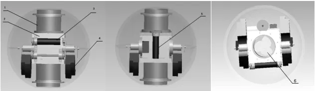
In order to show the design results, a virtual proto-type of robot is built out by PRO/E three-dimensional software in accordance with the movement principle of the drive mechanism and the proposed idea. First, various parts of diagram of the spherical robot were drawn, and then these parts were assembled in the software. So an entire spherical underwater robot is presented in Figure 1.
The designed spherical underwater robot is com-posed of the following main components as shown in Figure 1: a catheter (1), a sleeve (2), a short axis motor (3), two heavy pendulums (4), a long axis motor (5) and a propeller (6). The power is mainly supplied by the propeller, the long-axis motor and a short-axis motor. The small gear located in the output axis of the motor engages the gear which is located outside the central catheter with each other, and the sleeve and the heavy pendulums rotate about the axis under the effect of the long-axis motor; the chain linked to the short-axis motor’s output engages another gear fixed in the short axis of driving heavy pendulum, thus the shell and the sleeve rotate along the shaft with the short-axis motor rotating.
Based on the above analysis, the robot designed can
move in the desired form by controlling the motor and propeller. The motors drive the heavy pendulums to rotate along the perpendicular axis, so the spherical body can change the angles of roll, pitch and yaw. The direction of the propeller changes with the shell rotat-ing. In short, the catheter is adjusted to the predeter-mined direction and, the propeller provides thrust, then the robot moves forward.
The robot designed mainly has great advantages in the following aspects: (1) The robot adjusts attitude by driving the heavy pendulum and moves flexibly; (2) all parts of the robot are mounted inside the closed shell, so it has a good sealing performance and the excellent compression capability; (3) robot sails with only one propeller, so it is low cost, and the propeller is mounted in the middle of the catheter so that it is protected effectively.
3 SIMULATION MODEL AND THEORETICAL
[image:2.516.100.416.57.149.2]EQUATIONS
Figure 2. Simplified model.
[image:2.516.273.431.389.527.2]Omni-directional movement’s feasibility of the spher-ical robot needs to be validated, and the dynamics performance of the underwater robots also needs to be studied clearly. So the hydrodynamic of the robot needs to be calculated and analyzed in detail. Accord-ing to the current study which is only on the sphere, the hydrodynamic results cannot satisfy the require-ments of this novel robot with an additional central conduit. The effects of the catheter’s diameter on the hydrodynamic are unclear, so it is necessary to con-duct further analysis on the designed robot. Because
the outer surface of the spherical shell and the inner surface of the catheter are contacted with water, the structure of the robot can be simplified into the “cath-eter-shell" model, ignoring the internal driving struc-ture. The simplified result is shown in Figure 2.
In recent years, with the computer technology and the improved computing technology, the computa-tional fluid dynamics (CFD) has also been greatly developed. In particular, it has an outstanding perfor-mance on the ship’s hydrodynamic numerical simula-tion technology, because it can quickly obtain more detailed information on the flow field with low cost and non-contact measurement. The scale effect and the measurement error are eliminated. In this paper, the modified k-ε model was used to solve the correc-tion of hydrodynamic coefficients, and the model has good numerical stability and the pressure gradient precision, which is currently the most widely-used model to solve the viscous hydrodynamic turbulence. According to hydrodynamic theory, the related equa-tions are shown as follows:
The equation for turbulent kinetic energy:
i t
k b M k
i j k j
pk pku k
G G Y S
t x x x
(1)
The equation for dissipation rate:
2
1 3 2
i t
i j j
k b M
p p u k
t x x x
C G C G C Y S
k k
(2)
where Gk is the turbulent kinetic energy, which is
caused by the average gradient; Gb is also the
tur-bulent kinetic energy, which is caused by the buoyan-cy; YM is the contribution term about the pulsating
diffusion; C1, C2 and C3 are the empirical
con-stants;k and are the values of the Prandtl ,
which are related to the turbulent kinetic energy k and dissipation rate
; Skand S are the defined sourceterms.
Based the theoretical results of David Taylor Naval Ship Development Center in 1967, the equations of the robot’s dynamic model are simplified according to the spherical symmetry. It is assumed that the center of gravity and center of buoyancy are in the same location, and the moments of inertia of each axis are equal. Therefore, the six degrees of freedom’s motion equations are derived t as follows:
-x y z x x y y z zm u vr wq F X
m v wp ur F Y
m w uq vp F Z
I p K
I q M
I r N
(3)
[X, Y, Z, K, M, N] are the six degrees of freedom hydrodynamics in the above formula, and the hydro-dynamics can be expressed by the hydrodynamic co-efficients. However, with the expanded order increas-ing, the number of hydrodynamic coefficients expands rapidly. Fortunately, the low order coefficients play a major role. According to the particularity of the spe-cific structure, the drag coefficients and added mass coefficients are calculated in this paper.
4 SIMULATION AND IDENTIFICATION
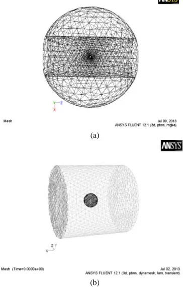
This paper proposed a detailed analysis on hydrody-namic of the spherical robot by FLUENT integrated in ANSYS. First, the simplified model from PROE was divided into meshes in ANSYS, and then the boundary conditions were set in FLUENT. The ball meshes and the fluid domain meshes were shown in Figure 3:
(a)
[image:3.516.273.455.267.552.2](b)
Figure 3. Fluid domain meshes.
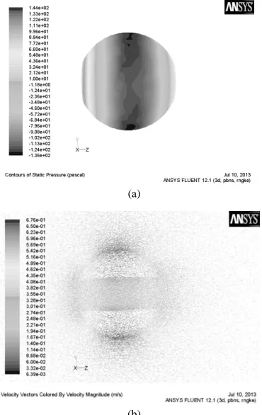
are shown in Figures 4. The pressure in front of the robot is the greatest, and the pressure in the rear is slightly smaller. The pressure on both sides is the minimum. In contrast, it can be observed from the distribution of the flow field around the robot. The velocity is small around the inner tube, as well as in the front and rear of robot. And it is large around both sides of the robot.
(a)
[image:4.516.265.464.98.206.2](b)
Figure 4. Fluid pressure and velocity field.
During the dragging experiments, the boundary conditions were set into the same type of the above simulation. Fluid inlet velocity was respectively set to be 0.25m/s, 0.5m/s, 0.75m/s and 1m/s, and the drift angle of robot is 0. The resistance values of the robot were drawn in Table 1:
Table 1. Resistance of straight shipping.
Velocity (m/s) 0 0.25 0.5 0.75 1
Resistance(N) 0 1.93 7.61 17.0 30.15
Because the structure of the robot along the longi-tudinal axis is symmetry, the effects of attack angle and drift angle on the hydrodynamic are the same. Thus the resistances in different drift angle were iden-tified. At velocity which is 0.5m/s, the drift angle was respectively set to be 0 degree, 15 degrees, 30 degrees, 45 degrees, 60 degrees, 75 degrees and 90 degrees.
[image:4.516.62.247.148.441.2]The resistance values in the inertial coordinate system were obtained by simulation, as shown in Table 2:
Table 2. Resistance of oblique shipping.
Angle (°) Xx (N) Xy (N) NZ (Nm)
0 7.61 0 0
15 8.51 3.38 0.31
30 9.31 4.57 0.45
45 10.12 4.5 0.39
60 10.38 3.45 0.17
75 10.18 0.78 0.12
90 9.98 0 0
Applying the method of least squares to fit for straight resistance, it can be drawn that the drag coef-ficient is approximately equal to 30. The oblique ship-ping resistance is more complex, which is difficult to find a suitable coefficient. The acceleration coeffi-cients of hydrodynamic forces, also known as added mass, were generally measured through the planar mechanisms (PPM). In this paper, FLUENT software was used to obtain the coefficients by calculating swaying and yawing. The principle of obtaining addi-tional mass was expressed as follows:
2 sin cos - sinx A t
v x A t
a x A t
(4)
2 2sin cos
sin A A
A
F F
F t v a
A A
(5)
2 cos A F A
(6)
Where FA is the hydrodynamic amplitude about
additional mass.
The UDF conditions about swaying are shown as follows:
cos 0.5 0.5 w t u (7)
The UDF conditions about yawing are shown as follows:
cos 0.5 6 0.5tan cos 0.5
12
q t
u
w u u t
(8)
[image:4.516.266.459.336.434.2](a)
(b)
Figure 5. Monitoring curve.
Table 3. Values of the additional mass.
11 22 33 44 55 66Value 20.4 22.5 22.5 0.00 0.01 0.01
The position forces of underwater robot which were related to the angle velocity were generally measured by the cantilever mechanism. The simulation needed to maintain constant linear velocity u of the robot in accordance with the physical experiment’s setting, and the different angular velocities were obtained by changing the arm length R. Under the above condi-tions, the calculated rotational resistances were listed in Table 4. By the UFD method, the transient analysis was executed. As can be seen from the table, the torque coefficients were so small. The values of the rotating were shown in Table 4:
Table 4. Values of the rotating.
(rad) 0.1 0.2 0.3 0.4 0.5Value 0.0001 0.003 0.007 0.012 0.02
[image:5.516.54.295.50.477.2]5 EXPERIMENT
Figure 6. Robot experiment.
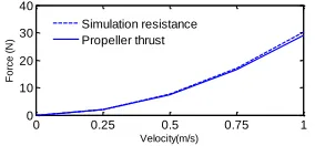
In order to verify the validity of the simulation, the drag resistance experiment of the spherical robot was implemented in the pool. The maximum velocity of the robot and the propeller thrust was got as shown in Figure 7, and the data tested in the experiment are almost consistent with the simulation data in Table 1.
Figure 7. Data of the simulation and experiment.
6 CONCLUSIONS
The designed spherical robot before manufacturing was simulated and calculated by the CFD, which is highly efficient for getting the comprehensive hydro-dynamic results. The initial theoretical studies would provide great help to optimize and build the dynamics model of robot. This approach is more natural, less spending and time-saving. Above simulation results meet the needs of the design studies, but for the accu-racy of the hydrodynamic values, the physical proto-type experiments are needed to be finished in the fu-ture.
ACKNOWLEDGEMENT
This paper is supported by China National Natural Science Foundation (51175048).
REFERENCES
[1] Chen Qiang, & Zhang Lin-gen. 2010. “Analysis of cur-rent situational development trend of US military UUV.”
Ship Science and Technology, 32 (7): 129-134.
[2] Choi, H.T., Hanai, A., Choi, S.K. & Yuh, J. 2003. “De-velopment of an underwater robot, ODIN-III.” In IEEE International Conference on Intelligent Robots and Sys-tems, pp: 836-841.
0 0.25 0.5 0.75 1
0 10 20 30 40
Velocity(m/s)
F
o
rce
(
N
)
[image:5.516.256.461.69.159.2] [image:5.516.292.434.260.326.2][3] Marc Carreras Perez. 2008. “A proposal of behav-ior-based control architecture with reinforcement learn-ing for an autonomous underwater robot.” University of Girona Ph. D dissertation, pp: 47-60.
[4] Xichuan L & Shuxiang G. 2012. “Development of a spherical underwater robot equipped with multiple vec-tored water-jet-based thrusters.” Journal of Intelligent &
Robotic Systems, (67), pp: 307–321.
[5] Xiaojuan L, Hanxu S & Qingxuan J. 2010. “Principle and dynamic analysis of a new-type spherical underwa-ter vehicle.” Journal of Beijing University of Posts and
Telecommunications, 33(3), pp: 20-23.
[6] Le Cair, B. A. Hamielec, & H. Pruppacher, 1970. “A
numerical study of the drag on a sphere at low and in-termediate Reynolds bumbers.” Journal of the
Atmos-pheric Sciences, 27(2): 308-315.
[7] Chang H X, Miao G P, & Liu Y Z. 1995. “Numerical simulation of viscous flow around a rolling cylinder with ship like section.” China Ocean Engineering, 9 (1): 9218.
[8] Debarros E A, Pascoal A, & Desa E. 2008. “Investiga-tion of a method for predicting AUV derivatives.” Ocean
Engineering, 35(16): 1627 - 1636.