© 2016, IRJET | Impact Factor value: 4.45 | ISO 9001:2008 Certified Journal
| Page 2712
“Modelling and Analysis of a Chassis Frame by Using Carbon Fiber and
E-Glass Epoxy as Composite Material: A Comparative Study”
Archit Tomar
1& Dheer Singh
21
School of Civil and Mechanical Engineering, Galgotias University, Greater Noida, India
2
Assistant Professor, School of Civil and Mechanical Engineering, Galgotias University, Greater Noida, India
---Abstract:
In Automobile the word chassis Frame means the part of automobile that hold all the important part of vehicle like Engine, Steering Systems, Suspension System etc and all the components constitute together to form a chassis. The conventional chassis is very heavy and bulky in nature due to that it contributes in higher emission and less efficiency of vehicle. In this paper firstly the chassis frame of Eicher truck 11.0 is modeled in CAD software and the further analysis is done in ANSYS by using the composite material like carbon fiber and E-Glass Epoxy. Modal analysis is done to study the vibration characteristics of the chassis frame also to know the natural frequency of the chassis frame and further Harmonic analysis is done to know the von misses stress in the chassis frame at that natural frequency which incurs maximum deformation in chassis frame after that the results of all the thee materials compare to know which is suitable material for the chassis frame.Keywords
:
Chassis Frame, Composite Material, Modal Analysis, Harmonic Analysis, Strength Comparison1. INTRODUCTION:
Frame of a vehicle is act like a skeleton it holds all the important component of a automobile like engine, steering systems, suspension, drive line, differential and all the essential components which constitute together to form a chassis. Chassis Frame must be stiff enough to withstand all the forces and loads acting on it statically and dynamically and forces like shock, twist and vibration. Composite material like carbon fiber and E-glass Epoxy fiber recently gained a wide acceptance in the automobile industry due to their light weight and high strength as compare to conventional automobile frame which is manufactured from steel and its alloy. Increasing demand of highly efficient and less weight automobile’s have made the researcher to do brain storming to search new materials and composite materials gained wide attention to be introduced in auto
vehicle due to their less dense and high strength and stiff in nature.
Finite element analysis is most widely used analysis technique due to its ease of use and good comparable results. By providing suitable boundary conditions on can do the analysis like static, modal and harmonic analysis In this paper Modal analysis is done to determine the natural vibrating frequency of the chassis frame by using steel-52, carbon fiber and E-glass epoxy Fiber and maximum deformation also coming out at particular natural frequency . After that Harmonic analysis of chassis frame is done in harmonic analysis the natural frequency at which at which maximum deformation is incur at chassis frame is taken as input and corresponding von misses stress is extract . On the basis of modal analysis and harmonic analysis a comparison is done of all the three material’s which is been used in this comparative study.
2. DETAILS OF CHASSIS FRAME
Model- EICHER 11.10
Side bar cross section= 210mm×76mm×6mm Number of side bar= 2
Number of cross bar= 6 Channel = C- channel Rear overhang= 1620mm Front overhang= 935mm Wheel base= 3800mm Capacity of truck =8 ton
Weight of body and engine= 2 ton
Load Acting on Chassis Frame =8000 Kg = 78480N
© 2016, IRJET | Impact Factor value: 4.45 | ISO 9001:2008 Certified Journal
| Page 2713
Over loaded Truck Capacity = 1.25%×78480=98100NTotal Load on Chassis Frame = 19620+98100=117720N
Load Acting on single frame = Total load/2= 58860N
3. MATERIAL PROPERTIES:
Table 1: Material Properties
Figure 2: Meshing Of Chassis Frame
4. CAD Design of Chassis Frame:
[image:2.595.315.568.483.604.2]Catia V5R19 is used to modeled the chassis frame of Eicher11.0.3-D model of the chassis frame is shown in Figure 1 below.
Figure 1: 3-D Model Of chassis Frame
5. MESHING OF CHASSIS FRAME:
The finite element method (FEM) is a numerical technique for finding approximate solutions to boundary value problems FEM subdivides a large problem into smaller, simpler, parts, called finite elements Meshing of chassis frame is done in Ansys R 14.5 and method used for meshing is tetrahedrons surface mesher .The size of elements is kept as minimum as possible to get the accurate results and at some points the finer meshing is also done to get better results. Figure 2 clearly shown
the meshing of the chassis frame which is been done in ANSYS R14.5.
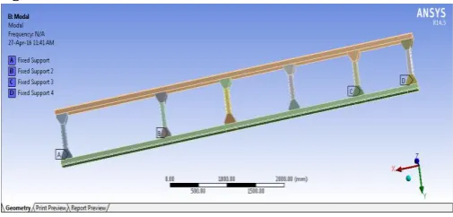
6. BOUNDARY CONDITIONS FOR MODAL
ANALYSIS:
While doing software based analysis there is need to apply boundary conditions. In Modal analysis the front two and last two cross member are fixed there is no need to apply loading conditions while doing modal analysis ,natural frequencies of chassis frame is outcome in modal analysis. Boundary conditions for modal analysis
is shown in
figure3.
Figure 3: Boundary conditions for Modal Analysis
7. MODAL ANALYSIS:
Modal analysis is used to judge the behavior of a body under vibrational conditions and corresponding natural frequency is determine Dynamic analysis can predict these variables with respect to time/frequency. To determine natural frequency of component it is basic design property. Natural frequency information is also helpful for avoiding resonance, reducing noise.
SL.No. Properties Units Steel- 52(st-52)
Carbon
Fiber E-Glass Epoxy Fiber
1 Density Kg/m3 7850 1500 1983
2 Young’s
Modulus N/mm 2×10
11 1.55×10¹¹ 7.8×10¹¹
3 Poisson
Ratio - 0.3 0.38 0.27
4 Ultimate tensile strength
© 2016, IRJET | Impact Factor value: 4.45 | ISO 9001:2008 Certified Journal
| Page 2714
In this paper the intention of doing the modal analysis isto determining the natural frequency of chassis frame at which maximum deformation incur into the chassis frame so that this maximum deformation natural frequency is used as input in harmonic analysis and corresponding stress is taken as out of all the materials that has been used in this analysis.
Table 2: Steel -52
Table 3: Carbon Fiber
Table 4: E –Glass Epoxy
As clearly mentioned in Table 2,3 and4 the natural frequencies of the steel-52 ,carbon fiber and E-Glass Epoxy fiber and the corresponding deformation is mentioned for every natural frequency in harmonic analysis the frequency that I been taken as input which has the highest deformation.
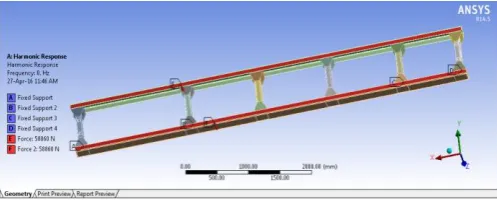
8. BOUNDARY CONDITIONS FOR HARMONIC
ANALYSIS:
In Harmonic analysis front two last two and also loading condition is applicable while doing analysis and most importantly frequency is taking as input while doing
[image:3.595.316.565.137.237.2]modal analysis and at that particular frequency the stress is taking is output.
Figure 4: Boundary conditions for Harmonic Analysis
9. HARMONIC ANALYSIS:
Harmonic analysis result is used to verify the steady-state response of a linear structure, enabling researches, engineers and chassis designer to determine whether in which the chassis can withstand resonance, fatigue or other structural problems related to vibration during its operating life.
Here in this paper the natural frequency which has highest deformation are uses as input and corresponding stress induced is taken as output which is used to compare that which material has highest and lowest von misses stress induced.
9.1 Steel -52 Harmonic Analysis Results:
Naturalfrequency(Hz) Deformation (mm)
42.49 3.28
83.40 3.301
91.46 3.78
114.64 9.95
128.77 10.25
143.11 11.10
Natural
frequency(Hz) Deformation (mm)
84.107 7.56
166.66 7.58
175.22 8.88
223.95 9.67
226.38 22.77
258.12 23.719
Natural
frequency(Hz) Deformation (mm)
52.816 6.5
103.8 6.55
113.68 7.50
142.94 19.785
160.55 20.309
© 2016, IRJET | Impact Factor value: 4.45 | ISO 9001:2008 Certified Journal
| Page 2715
9.2 Carbon Fiber Results:
9.3 E-Glass Epoxy Fiber:
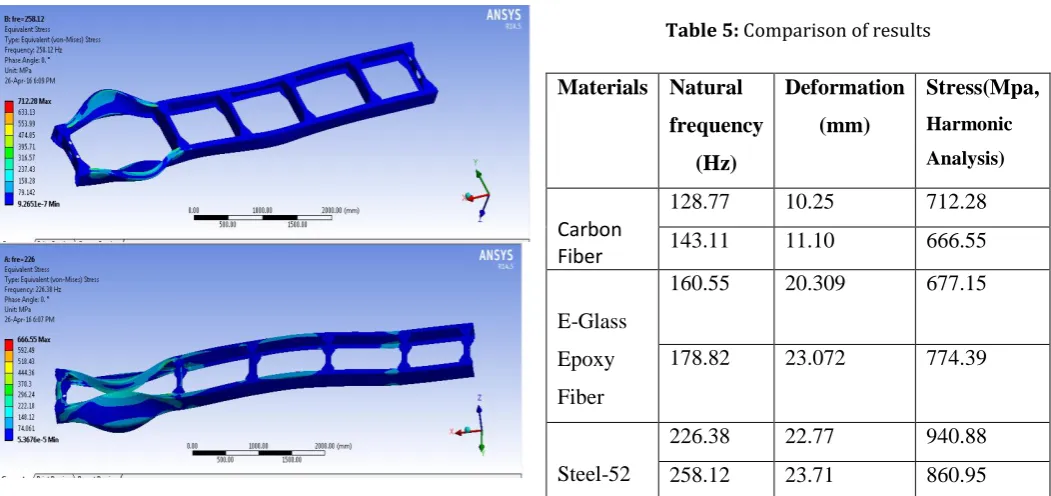
[image:4.595.38.564.121.369.2]10. RESULTS AND DISCUSSION:
Table 5: Comparison of results
Materials Natural
frequency
(Hz)
Deformation
(mm)
Stress(Mpa,
Harmonic
Analysis)
Carbon
Fiber
128.77
10.25
712.28
143.11
11.10
666.55
E-Glass
Epoxy
Fiber
160.55
20.309
677.15
178.82
23.072
774.39
Steel-52
226.38
22.77
940.88
258.12
23.71
860.95
Composite materials shows a less von misses stress as compare to structural steel- 52 at the natural frequency at which maximum deformation incur onto the chassis frame that and also the density of the composite material is very less which helps to drop down the weight of chassis frame and assist in increasing the efficiency of the automobile. The Epoxy Glass Fiber have shown a little bit higher deformation than steel its due to low stiffness but if the thickness of the epoxy glass chassis frame is increases than deformation will be less. Composite material is very costly as compare to other metal used in auto vehicle chassis frame which incur some extra cost on the consumer when cost will not be the factor the best alternative for the automobile and chassis frame is composite materials. The results of the harmonic analysis give a clear indication that the maximum stress induced is in steel and minimum stress induced is in composite material.
11. REFERENCES:
1.Vijaykumar V. Patel, and R. I. Patel, “Structural analysis of a ladder chassis frame”, World Journal of Science and Technology 2012, 2(4):05-08 ,ISSN: 2231 – 2587, April 21, 2012.
© 2016, IRJET | Impact Factor value: 4.45 | ISO 9001:2008 Certified Journal
| Page 2716
3. Archit Tomar & Rahul, “A Review On Hybrid Vehicles,Emissions Comparison With Conventional Vehicle And Policies Adoption For Promotion”, IMPACT: International Journal of Research in Engineering & Technology, Vol. 3, and Issue 12, Dec 2015, 11-20.
4. Yogendra S. Rajput1, Vikas Sharma1, Shivam Sharma1, Gaurav Saxena, “A Vibration Analysis of Vehicle Frame”, IJERA, Vol. 3, Issue 2, April 2013, pp.348-350.
5. Dr.R.Rajappan, M.Vivekanandhan, “Static and Modal Analysis of Chassis by Using Fea”, The International Journal Of Engineering And Science (Ijes), Volume- 2, Issue- 2, Pages-63-73, 2013.
6. Shaik khajamoinuddin, B.Balaji, “Modal and Static Analysis of a Standard All-Terrain Vehicle Chassis”, IJEDR, Volume 2, Issue 1.
7. Pravin A Renuke, “ Dynamic Analysis Of A Car Chassis”, International Journal of Engineering Research and Applications (IJERA), Vol. 2, Issue 6, November- December 2012, pp.955-959.
8. Archit Tomar ,Dheer Singh, “Static Analysis, Modal Analysis And Design Modification In Chassis Frame To Optimize Weight By Using Composite Material”, International Journal of Mechanical Engineering (IJME),ISSN(P):2319-2240 ISSN(E): 2319-2259,Vol. 5, Issue 1, Dec – Jan 2016,101-108,© IASET