© 2016, IRJET | Impact Factor value: 4.45 | ISO 9001:2008 Certified Journal | Page 128
Transient Stability Improvement Of IEEE 9 Bus System With Shunt
FACTS Device STATCOM
P.P. Panchbhai
1, P.S.Vaidya
21
Pratiksha P Panchbhai, Dept. of Electrical Engineering, G H Raisoni College of Engineering
Nagpur, Maharashtra,
India. E-mail: [email protected]
2
Prajakta S Vaidya (Assistant Professor), Dept. of Electrical Engineering, G H Raisoni College of Engineering
Nagpur, Maharashtra, India. E-mail: [email protected]
---***---Abstract -
This paper aims on improving the stability of a 9 bus power system under fault condition using a shunt FACTS device STATCOM or static synchronous compensator. In this paper an IEEE 9 bus system is modeled in MATLAB SIMULINK Software. STATCOM is a shunt FACTS device consisting of a voltage source inverter and a gate pulse generation circuit. It is connected to the transmission line through a coupling transformer. The results are obtained with STATCOM and without STATCOM. Analysis of the results shows that STATCOM has reduced the fault magnitude and has compensated the reactive power. It has also enhanced the voltage profile.Key Words:
IEEE 9 bus system, Static Synchronous
Compensator (STATCOM), Transient stability.
1. INTRODUCTION
The existing power systems are big and are extensive and complex. Due to increase demand of power transfer the transmission lines are becoming overburdened. As the burden on the transmission line increases the transient stability of the system is affected and hence the system becomes unstable. Some of the parameters involve are the rotor speed, bus voltage, power flow and other system variables. Transient stability is an important aspect in designing of a power system. Power system stability is the ability of the system, for a given initial operating condition, to retain a normal state of equilibrium after being subjected to a disturbance [6]. In order to improve the voltage transfer across the system it is convenient to connect a FACTS device rather than installing new transmission lines. A shunt FACTS device STATCOM can be used to improve the power transfer capability of a system. STATCOM consists of a voltage source inverter and a dc capacitor. It is connected to the transmission line through a coupling transformer.
2. POWER SYSTEM STABILIZER
The power system stabilizer (PSS) is a tool that measures improvements in system stability when added to a generator’s automatic voltage regulator (AVR) and improves the power system stability. Power system stabilizer controls the excitation depending upon the fluctuations of generator output power. Although the output power of the generator is decided by the turbine mechanical torque the generator output power can be change by changing the excitation value. PSS detects the change in generator output power and controls the excitation value and reduces the power swing rapidly. The main function of power system stabilizer is to damp generator rotor oscillations which are oscillations due to electromechanical dynamics and are known as electromechanical oscillations [2]. The PSS is a feedback controller, part of the control system for a synchronous generator, which acts through the excitation system, adding a signal to modulate the field voltage.
There are two types of stabilizer 1) Generic power system stabilizer model using the acceleration power (Pa= difference
between mechanical power Pm and output electrical power
Peo) and a 2) Multi-band power system stabilizer using the
speed deviation (dw). In this paper Generic power system stabilizer block is connected to the synchronous machine. It consists of a general gain, low-pass filter, a washout high-pass filter, phase-compensation system, and an output limiter. The input to the power system stabilizer is the synchronous machine speed deviation with respect to nominal (dwin pu) or the acceleration power (Pa=Pm-Pe in
pu). The output of pss is the stabilization voltage in pu which is connected as input to the excitation system.
© 2016, IRJET | Impact Factor value: 4.45 | ISO 9001:2008 Certified Journal | Page 129 important factor as the damping provided by PSS is directly
[image:2.595.40.278.143.427.2]proportional to the gain up to certain gain value after that the damping begins to decrease.
Fig-1: Power system stabilizer
3. STATCOM
[image:2.595.309.546.198.394.2]
Fig -2: Schematic diagram of basic STATCOM
STATCOM is a static synchronous compensator, it is a shunt controller used to inject the current and control the voltage. It is connected to the transmission line through a coupling transformer. The shunt controller is use only to consume or to supply the reactive power. STATCOM consists of a voltage source inverter, which is used to convert dc voltage at its input terminal into three phase ac voltage. STATCOM can be applied with two basic control which includes (a) control of dc voltage across dc capacitor and (b) regulation of the ac voltage of power system at the bus bar, where STATCOM is installed. The basic principle of STATCOM involves the generation of controllable alternating current voltage source behind a transformer leakage reactance with a voltage source converter connected to a DC storage capacitor. The difference in voltage across the reactance produces active and reactive power exchanges between the STATCOM and the power system.
STATCOM in this paper consists of a gate pulse generator circuit which is use to generate the gatepulses for the firing of the IGBT/Diode of the voltage source inverter. VSI is used to produce the output voltage. To the gate pulse generator input is given as a three phase current which is then converted to d-q frame of reference by parks transformation then its value is compared with the reference voltage by the PI controller and again it is converted to three phase ia, ib and
ic current which is feed to three separated PI controllers.
Here it is compared with the triangular wave and if the given condition is satisfied then pulses are generated which are the input to the VSI. Voltage Source Inverter has filters and IGBT/Diode which is use to generate the output voltage.
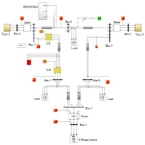
4. STANDARD IEEE 9–BUS POWER SYSTEM
Fig-3: IEEE 9 bus power system without STATCOM
Above fig shows MATLAB model of IEEE 9 bus power system without STATCOM. The system is prepared using the standard 9 bus system data [1].
Fig -4: IEEE 9–bus power system with STATCOM
[image:2.595.313.547.469.702.2]© 2016, IRJET | Impact Factor value: 4.45 | ISO 9001:2008 Certified Journal | Page 130 system consists of three generators, three transmission lines,
three transformers and three loads. Synchronous machine are associated with the generator 2 and generator 3. Also the power system stabilizer is connected to the synchronous machine of generator 2 and 3. Bus 1 is the source bus, Bus 2 and 3 are the generator or the voltage bus as the generators are directly connected to these buses, and bus 4,5,6,7 8 and 9 are the load buses.
[image:3.595.307.560.120.323.2]5.
DATA SHEET OF 9 BUS SYSTEM
Table-1: Prefault Network Admittance including load Equivalents
BUS
No Impedance Admittance
R X G D
Generator
No 1 1-4 0 0.1184 0 -8.4459
No 2 2-7 0 0.1823 0 -5.4855
No 3 3-9 0 0.2399 0 -4.1684
Transmission Line
4-5 0.0100 0.0850 1.3652 -11.6041
4-6 0.0170 0.0920 1.9422 -10.5107
5-7 0.0320 0.1610 1.1876 -5.9751
6-9 0.0390 0.1700 1.2820 -5.5882
7-8 0.0085 0.0720 1.6171 -13.6980
8-9 0.0119 0.1008 1.1551 -9.7843
Shunt Admittance
Load A 5-0 1.2610 -0.2634
Load B 6-0 0.8777 -0.0346
Load C 8-0 0.9690 -0.1601
4-0 0.1670
7-0 0.2275
9-0 0.2835
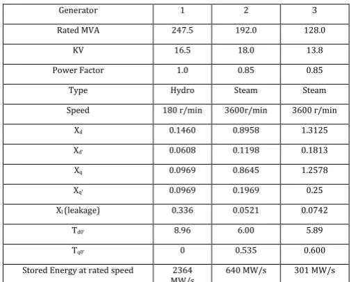
Table-2: Generator Data
Generator 1 2 3
Rated MVA 247.5 192.0 128.0
KV 16.5 18.0 13.8
Power Factor 1.0 0.85 0.85
Type Hydro Steam Steam
Speed 180 r/min 3600r/min 3600 r/min
Xd 0.1460 0.8958 1.3125
Xd’ 0.0608 0.1198 0.1813
Xq 0.0969 0.8645 1.2578
Xq’ 0.0969 0.1969 0.25
Xl (leakage) 0.336 0.0521 0.0742
Td0’ 8.96 6.00 5.89
Tq0’ 0 0.535 0.600
Stored Energy at rated speed 2364
MW/s 640 MW/s 301 MW/s
The generator internal voltage and their initial angles are given in pu by
2717
.
2
0566
.
1
101
E
7315
.
19
0502
.
1
202
E
1752
.
13
0170
.
1
303
E
The system base is chosen to be 100 MVA and all the impedance values are taken corresponding to this base. Table 1 shows the equivalent shunt admittance for the load and the corresponding Y matrix is given in [1]. Table 2 gives the generator data were generator 1 is hydro and generator 2 and 3 are steam generator. The transmission line is having π connections. The system is first tested with fault and without the STATCOM connected. After that the results are obtain with fault and with the device connected in the system. Fault is created between bus no. 5 and 7. The parameters which are observed are line voltage, rotor speed, active power and the reactive power.
[image:3.595.36.289.267.654.2]6.
SIMULATION RESULTS
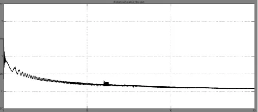
[image:3.595.305.561.621.743.2]© 2016, IRJET | Impact Factor value: 4.45 | ISO 9001:2008 Certified Journal | Page 131 Fig-6: Rotor speed with STATCOM
[image:4.595.304.568.77.223.2]From fig 5 the result shows that the rotor speed is fluctuate during the fault condition and fig 6 shows that STATCOM has improve the rotor speed to the value of almost 1 pu without any fluctuation even during the fault condition.
Fig-7: Active power without STATCOM
[image:4.595.36.289.108.228.2]Fig
-8: Active power with STATCOM [image:4.595.309.563.262.373.2]Fig 7 and 8 shows the output active power without device and with device respectively under fault condition the device has compensated the active power from 0.7 to 0.2 pu and also the magnitude of fault is reduced.
Fig-9: Reactive power without STATCOM
Fig-10: Reactive power with STATCOM
[image:4.595.36.290.317.440.2]Fig 9 and 10 shows the output reactive power without STATCOM and with STATCOM respectively the device has compensated the reactive power from 0.18 pu to 0.2 pu as STATCOM is use for reactive power compensation it has done so.
Fig-11: Line Voltage without STATCOM
[image:4.595.309.560.480.657.2]© 2016, IRJET | Impact Factor value: 4.45 | ISO 9001:2008 Certified Journal | Page 132 Fig 11 and 12 shows the line voltage between bus 8 and bus
9 with and without STATCOM. Due to the presence of STATCOM the magnitude of fault has decrease a lot form 1.5 pu to 0.15 pu.
7. CONCLUSIONS
The simulation result shows that the device has enhanced the transmission capacity of line. The presence of STATCOM has reduced the fault magnitude as a result of which the main system losses have also been reduced. STATCOM is known for reactive power compensation and it has up to some extend shows compensation of power.
In this paper simulation of STATCOM has verified that it can be applied to the power transmission line to compensate the reactive power and also to improve the voltage profile. It is use for the improvement of transient voltage behaviour of the power system.
8. REFERENCES
[1] P.M. Anderson and A.A Fouad, “Power system Control and
Stability”, Iowa State University Press.
[2] ANDREA ANGEL ZEA, “Power System Stabilizers for The
Synchronous Generator Tuning and Performance Evaluation” CHALMERS UNIVERSITY OF TECHNOLOGY Goteborg, Sweden 2013.
[3] Sreevidya T.R , Dawnee S “Optimal Interaction of PSS
and SSSC in a Power System Network” International Conference on Emerging Trends in Science, Engineering and Technolog IEEE 2012
[4] Prabha Kundur, ―Power System Stability and Control‖,
Electric power research Institute, Tata McGraw-Hill Publishing Company Limited,Sixth Reprint 2008
[5] V.K.Ramachandaramurthy,R.N.Mukerjee,N.M. Mmuhamad Razali, “Power System Stabilizer Placement and Tuning Methods for Inter-area Oscillation Damping” First International Power and Energy Coference PECon 2006 November 28-29, 2006, Putrajaya, Malaysia
[6] Swaroop Kumar.Nallagalva,Mukesh Kumar Kirar, Dr.Ganga Agnihotri, “Transient Stability Analysis of the IEEE 9-Bus Electric Power System” International Journal of Scientific Engineering and Technology, 01 July 2012
[7] Dr. S. Titus*, B.J.Vinothbabu**, I. Maria Anton Nishanth**, “ Power System Stability Enhancement under Three Phase Fault with FACTS Devices TCSC, STATCOM and UPFC” International Journal of Scientific and Research Publications, Volume 3, Issue 3, March 2013
[8] Engr.Qazi Waqar Ali ¹, Prof.Dr.Azzam ul Asar, “ Smart
Power Transmission System Using FACTS Device ” International Journal of Engineering & Computer Science IJECS-IJENS Vol:12 No:06 December 2012
[9] Dr. S. Titus, B.J.Vinothbabu, I. Maria Anton Nishanth, “Power System Stability Enhancement Under Three Phase
Fault with FACTS Devices TCSC, STATCOM and UPFC” (IJITR) international journal of innovative technology and research Volume No. 1, Issue No. 1, December January 2013
[10] Juan Segundo-Ramirez1 and A. Medina2,” Analysis of
Power Electronic Controllers in Electric Power Systems Using Simulink” www.intechopen.com