© 2016, IRJET | Impact Factor value: 4.45 | ISO 9001:2008 Certified Journal
| Page 1363
Image Stitching using Harris Feature Detection
Shreyas Mistry
1, Prof. Arpita Patel
21
M. Tech. Student, Electronics & Communication, Chandubhai S. Patel Institute of Technology
2
Assi. Professor, Electronics & Communication, Chandubhai S. Patel Institute of Technology
---ABSTRACT
Image stitching is the process in which different photographic images are integrated together to form a segmented panorama or a high resolution image. Multiple images are overlapped and blended to form a wide angle panoramic image. The entire image stitching process is done by images taken from a camera and then applying the process on a computer software. The main steps include image acquisition, image registration image blending. The image registration process used in this method is a feature based method which uses HARRIS corner detection algorithm for feature detection. The image stitching algorithm is then processed to give a stitched panoramic image.
KEYWORDS
Image Stitching, Image Mosiacing, Panorama, Harris Corner, Feature detection, feature matching.
1.
INTRODUCTION
Image stitching [1] is the process of combining multiple photographic images with overlapping fields of view to produce a segmented panorama or high-resolution image. It is also known as image mosaicing. Most common approaches of image stitching require exact overlaps between images and identical exposures to produce seamless results. In addition of using image stitching in computer vision and computer graphics applications, there are some digital cameras can stitch their photos internally [5]. Panoramic image mosaicing works by taking lots of pictures from an ordinary camera and stitching them together to form a composite image with a much larger field of view. The set of images may consist of two or more digital images taken of a single scene at different times, from different sensors or from different viewpoints. [2] The goal of registration is to establish geometric correspondence between the images so that they may be transformed, compared and analysed.
Image stitching techniques can be categorized into two general approaches: [3] direct and feature based techniques. Direct techniques compare all the pixel intensities of the images with each other, whereas feature based techniques aim to determine a relationship between the images through distinct features extracted
from the processed images. The latter method had the advantage of being more robust against scene movement, aster and has the ability to automatically discover the over lapping relationships among an unordered set of images.
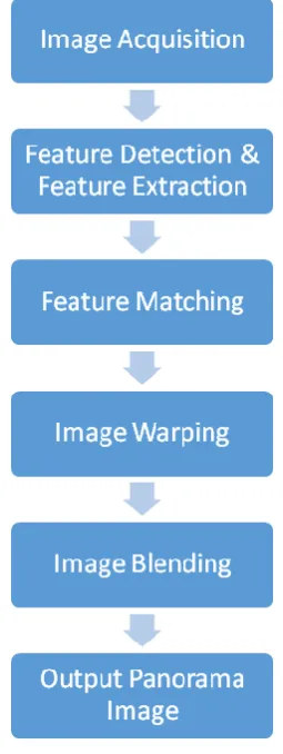
The concept of image stitching is primarily used in panorama image to view the scene containing more than one image, in a single image. This is achieved by using feature based concept of image registration in image processing. The entire process is done by correctly merging and aligning the photographed images into a single image. Image stitching consists of basic three steps: Image Acquisition, Image Registration, and Image Blending. The image registration step includes feature detection and extraction, feature matching and transforming the images with the help of a transformation model. The feature detection step can be executed in a number of methods by selecting various features in the images which are unique and robust. Out of all the feature detected, the corners are most versatile and gives the very good results. The corner detection method used in this paper is Harris corner detection method which used the Harris-Stephens algorithm to detect the corners in the given image.
The use of image stitching in real time applications is considered as a challenging field for image processing experts. It has wide applications in the field of video conferencing, video matting, video stabilization, 3D image reconstruction, video summarization, video compression, satellite imaging, panoramic image generation, image mosaicing and several medical applications. Medical image stitching has many applications in clinical diagnosis, such as diagnosis of cardiac, retinal, pelvic, renal, abdomen, liver, tissue and other disorders.
2.
LITERATURE SURVEY
© 2016, IRJET | Impact Factor value: 4.45 | ISO 9001:2008 Certified Journal
| Page 1364
methods which can be used for image mosaicing as well.Different image acquisition techniques such as image acquisition by camera rotations, image acquisition by camera translations, and image acquisition by a hand held camera and their properties in detail are discussed. The mathematics of image registration is discussed in detail. Different image registration methods using different similarity measures such as images registration using sum of squared differences, image registration using sum of product, image registration using standard deviation of differences, image registration by restricting the search set, image registration with step search strategy have been discussed in brief The image merging method of linear distribution of intensity differences which uses a linear ramp to spread the intensity differences of the pixels which are immediately next to the seam for blending pairs of grey level satellite proposed by D. L. Milgram have been given. The paper gives an idea that the concept of image stitching or panorama production can be used where the camera is unable to obtain the full view of the object of interest.
Pranoti Kale et al. [10] has given a technical analysis of image stitching algorithm. The paper gives a brief review on the image registration techniques used in the past as well as in the present era. It has been discussed that the image stitching process can be divided into three main steps of image calibration, image registration and image blending. The main approaches involved in image stitching viz. direct and feature based techniques are discussed in brief. The direct techniques work by directly minimizing pixel to pixel dissimilarities. Though these methods are computationally complex due to the process involved. And also hey are not invariant to image scale and rotation. Whereas the primary advantage of direct techniques is that they make optimal use of the information available in the image alignment. The feature based techniques work by extracting a sparse set of features and then matching them to each other. This technique is applied by establishing correspondences between points, lines, edges, corners or other geometric entities. The techniques namely Harris corner detector, SIFT, SURF, FAST, PCA-SIFT and ORB come under this technique.
3.
IMAGE STITCHING TECHNIQUES
3.1
Direct Techniques:
In direct technique, each pixel intensities of image are compared with each other. The main advantage of direct technique is that it minimizes the sum of absolute differences between overlapping pixels. In this technique, each pixels are compared with each other so
it’s a very complex technique. They are not invariant to image scale and rotation. Direct method optimally used the information gathered from the image alignment. It measures the contribution of every pixel in the image. The main disadvantage of direct techniques is that they have a limited range of convergence [1]. Direct Method uses information from all pixels. It iteratively updates an estimate of homography so that a particular cost function is minimized. Sometimes Phase-Correlation is used to estimate the a few parameters of the homography.
3.2
Feature based techniques
Feature based methods have become increasingly popular and widespread in mosiacing. This is particularly because of the strength of new algorithms and types of invariant features which have been demonstrated in the recent years. In feature-based technique, all main feature points in an image pair is compare with all features in the other image by using one of the local descriptors. For image stitching based on feature-based techniques, feature extraction, registration, and blending are different steps required for doing image stitching. Feature-based methods are used by establishing correspondences between points, lines, edges, corners or any other shapes. The main characteristics of robust detectors includes invariance to image noise, scale invariance, translation invariance, and rotation transformations. There are many feature detector techniques exist some of which are, Harris [12], Scale-Invariant Feature Transform (SIFT) [13], Speeded Up Robust Features (SURF) [12], Features from Accelerated Segment Test (FAST) [15], PCA-SIFT [16] and ORB [17] techniques.
© 2016, IRJET | Impact Factor value: 4.45 | ISO 9001:2008 Certified Journal
| Page 1365
[image:3.595.76.204.144.484.2]4.
IMAGE STITCHING FOR PANORAMA
Figure 4.1: Image Stitching Algorithm
4.1
Image Acquisition
The first step of any image vision system is image acquisition. Image acquisition [18] can be broadly be defines as the action of retrieving an image from some sources. Typically, the images required for image stitching can be acquired by three different methods. These methods include translating a camera parallel to the scene, rotating a camera about its vertical axis by keeping the optical centre fixed or by a handheld camera. The acquired images are assumed to have enough overlapping that the stitching can be done and also some other camera parameters are known.
Figure 4.2: Images Acquired With Camera Rotation
4.2 Feature Detection and Feature Extraction
The second step in image stitching is feature detection which is the main part of image stitching process. In an image, features of the image are the elements of that particular image. The basic idea to do feature detection is that, the image can’t be seen as whole an image but the special points in the image can be taken separately and then processed by applying feature detection methods.
Feature detection forms an important part of image stitching algorithm. The speed at which features in an image are detected is crucial in many applications. The detected feature points need to be described separately so that the correspondence between multiple views can be computed reliably and efficiently. Real-time processing of the images requires the feature detection, description, and matching to be as fast as possible. For better feature matching of image pairs, the points used to characterize the images need to satisfy two important conditions: firstly the feature points of the same scene in different perspective, viewpoint or illumination conditions should be just the same and secondly the points should have a sufficient amount of information in order to match with each other. Corners are the best features for matching. The most important feature of corner is that if there is a corner in an image then its neighbourhood will show an abrupt change in the intensity. Also, local feature descriptors describe a pixel in an image with its local content. There are many requirements of a local feature detector, such as it should be invariant to translation, rotation, scale, affine transformation, presence of noise, and blur. The Harris corner detector is an efficient feature detection operator and has been used widely. The Harris corner detector is rotation invariant and has adequate information for the feature matching process.
4.3
Harris Corner Detector
© 2016, IRJET | Impact Factor value: 4.45 | ISO 9001:2008 Certified Journal
| Page 1366
considering the speed the Harris Corner is the fastestthan the SIFT.
The Harris corner detector is a popular interest point detector due to its strong invariance to rotation, scale, illumination variation and image noise.
The Harris corner detector is based on the local auto-correlation function of a signal, where the local auto correlation function measures the local changes of the signal with patches shifted by a small amount in different directions. To find the corners in the input image, Harris method takes a look at the average intensity which is directional.
The mathematical form of the Harris corner detector basically finds the difference in intensity for a displacement of (u, v) in all directions [31]. Considering the gray intensity of pixel (u, v) be I(x, y), the variation of gray pixel (x, y) with a shift of (u, v) can be denoted as:
…4.1
Where; w(x, y) is the window function, I(x+u, y+v) is the shifted intensity value and I(x, y) is the intensity value.
Window function is either a rectangular window or a gaussian window which gives weights to pixels underneath.
We have to maximize the function E(u,v) for corner detection. That means, we have to maximize the second term.
…4.2
From the matrix in equation 5.3, it can be very easy to find the average intensity change in the specific direction and the specific direction orthogonal to the previous specific direction using Eigen values which are calculated from the matrix. These values can also be applicable to detect the position of the point which is the point on the edge or in the region for homogeneous or a corner.
If one eigen value is high and the other is low, the point is located on the edge line.
If both the values if the eigen vector are having low intensity, then the point is located in the homogeneous region.
If both the values of the eigen vector are high in the region, then the point is a corner.
After this equation, Harris and Stephens created a score, basically an equation, which will determine if a window can contain a corner or not [9].
…4.3
Where,
det (M) = λ1 λ2
trace(M) = λ1 + λ2
λ1 and λ2 are the eigen values of M
[image:4.595.352.522.309.422.2]So the values of these eigen values decide whether a region is corner, edge or flat.
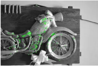
Figure 4.3 Harris Corner Detection
Figure 4.4: Harris Corner Detection
4.4 To set Relation of Feature Points in input
images
[image:4.595.352.522.496.612.2]© 2016, IRJET | Impact Factor value: 4.45 | ISO 9001:2008 Certified Journal
| Page 1367
of the image intensity values in their closeneighbourhood’s, the feature spatial distribution, or the feature symbolic description. Feature based registration methods are based on more precise features, often points or small blocks of reference and target image. It is assumed that two sets of features in the reference and sensed images represented by the CP’s (points themselves, end points or centres of line features, centres of gravity of regions, etc.) have been detected. The aim is to find the pairwise correspondence between them using their spatial relations or various descriptors of features.
Homography Estimation using RANSAC
RANSAC [8] is an abbreviation for Random Sample Consensus. It is an iterative method to estimate the parameters of a mathematical model from a set of observed data which contains outliers. It is a non-deterministic algorithm in the sense that it produces a reasonable result only with a certain probability, with this probability increasing as more iterations are allowed.
A basic assumption is that the data consists of inliers, the data whose distribution can be explained by some set of model parameters and outliers which are the data that do not fir the model. In addition to this, the data can be subject to noise. RANSAC also assumes that for a set of inliers, there exists a procedure which can estimate the parameters of a model that optimally explains or fits this data.
The input to RANSAC algorithm is a set of observed data values, a parameterized model which can explain or be fitted to the observations and some confidence parameters, RANSAC achieves its goal by iteratively selecting a random subset of the original data.
The basic RANSAC algorithm is as summarized below[7]:
1. Select randomly the minimum number of points required to detect model parameters.
2. Solve for the parameter of the model.
3. Determine how many points from the set of all points fit with a predefined tolerance €.
4. If the fraction of the number of inliers over the total number points in the set exceeds a predefined threshold τ, estimate the model parameters using all the identified inliers and terminate.
5. Otherwise, repeat steps 1 through 4.
This procedure is repeated a fixed number of times, each time producing either a model which is rejected because too few points are classified as inliers or a refined model together with a corresponding error measure.
The main idea of the verification model is, it should compare the correct probabilities that set of inliers was generated by a correct image match or the set of outliers was generated by a false image match.
An advantage of RANSAC is its ability to do robust estimation of the model parameters, i.e., it can estimate the parameters with a high degree of accuracy even when a significant number of outliers are present in the data.
[image:5.595.350.523.379.496.2]A disadvantage of RANSAC if that there is no upper bound on the time it takes to compute these parameters. When the number if iterations computed is limited, the solution may not be optimal and it may not even be one that fits the data in a good way.
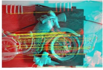
Figure 4.5: Feature Matching Between Two Images
4.5 Image Warping
© 2016, IRJET | Impact Factor value: 4.45 | ISO 9001:2008 Certified Journal
| Page 1368
The two images that will form the mosaic are warped, byusing the geometric transformation. While an image can be transformed in various ways, pure warping means that points are mapped to points without changing the colours. It can be mathematically based on any function from the (part of) plane to the plane. If the function is put in the original then it can be reconstructed.
There are two methods for generation of an image for any type of distortion.
Forward-mapping: A given mapping from sources to images is directly applied.
Reverse-mapping: A given mapping from sources to images, the source is found from the image.
In forward warping, the source image is mapped onto a cylindrical surface, but it can leave holes in the destination image as some pixels may never get mapped there. Therefore, inverse warping is generally used where each pixel in the destination image is mapped to the source image.
4.6 Image Blending
Once the source pixels have been mapped onto the final composite surface, the second step is to blend them in order to create an attractive looking panorama. Image blending is the technique which modifies the image gray levels in the vicinity of a boundary to obtain a smooth transition between images by removing these seams and creating a blended image by determining how a pixel in an overlapping area should be presented.
Image blending involves executing the adjustments figured out in the calibration stage, combined with the remapping of the images to an output projection[9]. Images are blended together and the seam line adjustment is done to minimize the visibility of seams between images. Once the source pixels have been mapped onto the final composite surface, the second step is to blend them in order to create an attractive looking panorama. If all of the images are in perfect registration and identically exposed, this is an easy problem.
There are many different pixels blending methods used in image stitching, such as feathering image blending, gradient domain and Image Pyramid blending [11].
Blending can be performed by using a binary mask which the object overwrites the pixel values of one image with the pixel values of another image. Also blending can be done by linearly combining the pixels of one image with those of the next image.
[image:6.595.345.529.237.323.2]Feathering image blending is a technique used in computer graphics software to smooth or blur the edges of a feature; it is the simplest approach, in which the pixel values in the blended regions are weighted average from the two overlapping images[20]. Sometimes this simple approach doesn't work well (for example in the presence of exposure differences). But if all the images were taken at the same time and using high quality tripods, therefore, this simple algorithm produces excellent results.
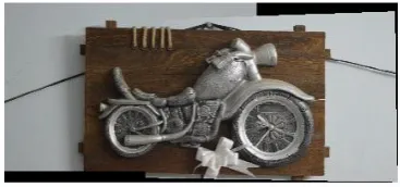
Figure 4.6: Final Stitched Panorama Image
5.
CHALLENGES ACCOSICATED WITH IMAGE
STITCHING
There are many challenges in image stitching such as [14]:
Noisy image data or data with uncertainties: An image is often corrupted by noise in its acquisition and transmission, the cost of extracting features is minimized by taking a cascade filtering approach.
Very larger images collection need for efficient indexing: large amount of images may lead to high processing time, since each image needs some processing.
The main challenge on image stitching is the using of handled camera which may lead to presence of parallax (a shift in apparent object position while observed from different angles of view), small scene motions such as waving tree branches, and large-scale scene motions such as people moving in and out of pictures. This problem can be handled by bundle adjustment.
Another recurring problem in creating photo-mosaics is the elimination of visible seams, for which a variety of techniques have been developed over the years [19].
6.
CONCLUSION
© 2016, IRJET | Impact Factor value: 4.45 | ISO 9001:2008 Certified Journal
| Page 1369
and basic technique of image stitching using Harriscorner detection.
We have seen the two different techniques used for image stitching namely direct and feature based techniques.
Furthermore, we have also discussed the general image stitching model and the process associated with each of the step. We detected featured in the images
The paper has discussed the harris corner detection algorithm in detail and also RANSAC algorithm to remove the outliers from the two images.
The literature review of image stitching shows that there is a space for improving the stitching process by various other techniques too.
7.
REFERENCES
[1].Ebtsam Adetet. al., ‘Image Stitching based on Feature Extraction Techniques: A Survey’, International Journal of Computer Applications, vol 99, no 6, 2014. [2].Lowe, ‘Distinctive Image Features from Scale-Invariant Keypoints’, International Journal of Computer Vision, vol 60, 2004.
[3].Parul Jain, VijayaShandliya, ‘A Review Paper Om Various Approaches for Image Mosiacing’, International Journal of Computational Engineering Research, vol 3, issue 4, 2014.
[4].Chia Yun Chen, ‘Image Stitching- Comparison and New Techniques’, University of Auckland, 1998. [5].Jin-jianLv, Gong-jian and Ji-yang Wang, ‘A New
Feature Matching Algorithm for Image Registration based on Feature Similarity’, Congress on Image and Speech Processing, 2008.
[6].Harris C., Stephens M., ‘A Combined Corner and Edge Detector’, Plessey Research Rake Manor, UK, 1988. [7].Konstantinos G. Derpanis, “The Harris Corner
Detector”, October2004.
[8].Ashwini P., Jayalaxmi H., ‘image mosaicing using SIFT and Corner Detection Algorithm’, international journal of advanced technology an engineering research, vol 4, issue 2, March 2014.
[9].V. Rankov, R.J. Locke, R.J. Eden, P.R. Barber, B. Vojnovic, “An algorithm for Image Stitching & Blending”, Proceedings of SPIE, Vol. 5701, March 2005.
[10]. Pranoti Kale, K.R. Singh, ‘A Technical Analysis of Image Stitching Algorithm’, ISCIT, Vol 6(1), 2015. [11]. Eden A, Uyttendaele&Szeliski, ‘Seamless Image
Stitching of Scenes with Large Motions and Exposure Differences’, Proceedings of the 2006 IEEE Computer
Scoiety Conference on Computer Vision and Pattern Recognition, vol 2, 2006.
[12]. Karthik, AnnisFathima, Vaidehi, ‘Panoramic View Creation using Invariant Feature Transform with Embedded Color Invariant Values’, IEEE Transactions
[13]. Oh-Seol Kwon and Yeong-Ho Ha, ‘Panoramic Video using Scale Invariant Feature Transform with Embedded Color Invariant Values’, IEEE International Transactions on consumer electronics, vol 56, May 2010.
[14]. Szeliski, R., “Image Alignment and Stitching”, Technical report.
[15]. Ke Yan and Rahul Sukthankar, ‘PCA-SIFT: A More Distinctive Representation for Local Image Descriptors’, IEEE Computer Society Conference in Computer Vision And Pattern Recognition, vol 2, 2004.
[16]. A.V. Kulkarni, J.S.Jagtag, V.K.Harpale, ‘Object Recognition with ORB and its Implementation on FPGA’, International Journal of Advanced Computer Research, 2013.
[17]. Shikha Arya, ‘A Review On Image Stitching and its Different Methods’, International Journal of Advanced Research in Computer Science and Software Engineering, vol 5, issue 5, May 2015. [18]. Hetal Patel, A. P., ‘Comprehensie Study And Review
of Image Mosaicing Methods’, International Journal Of Engineering Research and Technology, Vol 1, Issue 9, Nov 2012.
[19]. Mclauchlan, P., Jaenicke A., XH G. G., ‘image mosaicing using sequential bundle assignment’, BMVC, 2000.