© 2015, IRJET ISO 9001:2008 Certified Journal Page 222
STATIC AND DYNAMIC ANALYSIS OF A CNC MILLING SPINDLE
HAREESHA
11 PG Student, Department of Mechanical Engineering, BIET, Karnataka, India
---***---Abstract -
The spindle is the one of importantcomponents in the Milling machine of which static and dynamic characteristics is directly related to the
machining operation, precision, stability. The
performance of spindle system directly affects the overall machine specification. Static and Dynamic analysis of machine tool structures plays an important role on the efficiency and job accuracy of the machine tool. Static analysis is useful for estimating stresses, strains and deflections, where as dynamic analysis deals with the prediction of natural frequencies and corresponding mode shapes, which will intern, prevent the catastrophic failure of the machine tool. In the present work, an attempt has been made to study the static and dynamic behavior of spindle of a CNC vertical machining centre using finite element analysis measure the vibration of developed spindle experimentally. For this FEA model various loading conditions like static and dynamic analysis and operating conditions are applied using ANSYS to obtain the deflections and mode shapes.
Key Words: Finite Element Analysis, Spindle, Static Analysis, Dynamic Analysis, ANSYS.CEMB Vibration ANALYZER.
1. INTRODUCTION
Machine tools are generally equipped with spindles for locating the job holding tool or work, rotating the work or the tools and feeding the tool as in the case of drilling machine. The spindles are made out of hollow steel shaft with a provision at the front end for receiving the centering element. It is desirable that the axis of the hole and the axis of the spindle rotation be concentric. Machining accuracy depends to a considerable extent upon the rotational accuracy of the spindle, which transmits motion to the cutting tool or to the work. Generally machine tool spindles are made up of alloy carbon steel, heat-treated, to give a case hardened surface. Such a spindle possesses resistance to wear combined with a tough core for strength in torsion. Spindles of heavy
machine tools are made of manganese steel with subsequent normalization or hardening followed by high tempering. A typical spindle is shown in Figure 1.The spindles are supported inside the housing by means of more than one pair of bearings. The geometrical accuracy and surface finish of a machined component depends to a great extent on the quality of spindle bearings used. It is necessary to maintain an accurate and suitable location of the axis of the rotating spindle at all speeds and loads.
1.1Spindle Structure
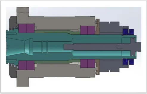
[image:1.595.310.557.498.656.2]The structure of the spindle is shown in Figure 1, the Standardized tool interface HSK (Hohlschaftkegel) is placed at the spindles front end. The spindle is supported by two sets of angular contact ball bearings in order to reducing the axial run out of the spindle and improving the axial stiffness of the spindle, the two sets of angular contact ball bearings are installed in the back to back. From the consideration of the BT-30 spindle design, the front and rear diameter of the bearing bore selected from is 45mm and 40mm. The selected bearing for the front end is B7009ETDBP4L. The selected bearing for the rear end is B7008 ETDBP4L.
Fig -1: Typical spindle structure
2. STATIC ANALYSIS
© 2015, IRJET ISO 9001:2008 Certified Journal Page 223 analysis can, however, include steady inertia loads (such
as gravity and rotational velocity), and time varying loads that can be approximated as static equivalent Static analysis is used to determine the displacements, stresses, strains, and forces in structures or components caused by loads that do not induce significant inertia and damping effects.
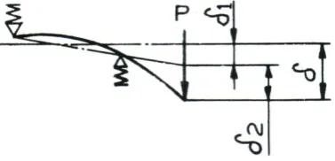
2.1 Theoretical calculation of spindle deflection Spindle deflection calculations have been carried out under the assumption that the housing deformation is of no consequence. The total deflection of the spindle is therefore due to the elastic deformation of the spindle and elastic deformation of the bearings. Ignoring the effects of housing deformation on the spindle, the total deflection of the spindle unit is due to the elastic deformation δ2 of the spindle itself together with δ1 the deflection caused by elastic deformation of the bearings. The total deflection of the bearing system due to load P at the point of application of load is shown in Figure 2.
Fig -2: Spindle Deflection Diagram
Nomenclature: = 1 +2
=Pz [1/SA*(a+L/L) 2+1/SB (a/L)2+a2/3e(a/Ia+L/IL)] (1) (Pz) = Load N
() = Deflection at the point of application of load, Pz mm (1) = Deflection due to radial yielding of the bearing, mm (2) = Deflection due to elastic bending of the spindle, mm (a) =Length of the overhanging portion of the spindle from the effective support of bearings.
(S) = P/ = Overall stiffness of the spindle unit, kgf/mm (SA)= Radial stiffness of the bearing near the load point, kgf/mm
(SB)=Radial stiffness of the bearing away from the load point, kgf/mm
(Ia) = Moment of Inertia of overhang portion of spindle (mm4)
(IL) = Moment of Inertia of spindle section between bearings (mm4)
(L) = Bearing span, mm (distance between the effective support points of front and rear bearings)
Bearing Specifications:
B7009 ETDBP4L= Front bearing Axial stiffness ( SA) = 260000 N/mm B7008 ETDBP4L = Rear bearing Axial stiffness (SB) = 230000 N/mm Where, 70 Series
08 & 09 I.D (Bore code) E 250 (Angle of contact)
T cage material (Phenolic resin) DB Grouping (Back to Back)
a = 46mm (overhang of spindle from the effective support of bearing)
L = 125mm (distance between the effective support positions of front and rear bearings)
MI of overhang portion of spindle, (Ia)
I = π/64 (D4 – d4)
I1 = π /64 (594 – 304) = 555.04 x 103 mm4
I2 = π /64 (594 – 224) = 583.31 x 103 mm4
I3 = π /64 (304 – 224) = 28.26x 103 mm4
Ia = (I1 + I2 + I3 / 3)
Ia= 388.87x 103 mm4
M.I of spindle section between bearings, (IL)
I = π/64 (D4 – d4)
I1 = π /64 (454 – 224) = 189.78 x 103 mm4
I2 = π /64 (454 – 274) = 175.20 x 103 mm4
I3 = π /64 (404 – 17.804) = 196.36x 104 mm4
I4 = π /64 (404 – 294) = 90.945 x 103 mm4
IL = I1 + I2 + I3 + I4 /4
IL = 163.07 x 103mm 4
Pz = 1120 N (Tangential cutting force)
=Pz*[1/SA*(a+L/L) 2 +1/SB (a/L) 2+ a2/3e (a/Ia+L/IL)]
= 0.01284 mm.
2.2 Optimum bearing span length
L0 = [6EIL ( + ) + ( ) Q] 1/3 (2)
[image:2.595.62.251.382.473.2]© 2015, IRJET ISO 9001:2008 Certified Journal Page 224 Q = Trial value for iterative determination of L0 = 4a
L0= 114.23mm
2.3 Spindle Stiffness
Stiffness (K) = (3)
=
K = 87 X 103 N/mm
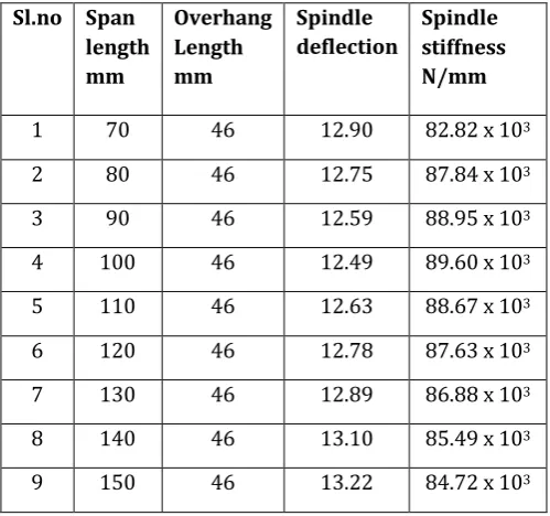
[image:3.595.308.554.101.330.2]Here the span length is varied from 70 mm to 150 mm. The variation of span length may become essential to accommodate the shaft. By considering spindle nose size BT-30 taper, the overhang of the spindle is around 46 mm from the front bearing center as show in the table 1.
Table -1: Variations of deflection and stiffness values
Sl.no Span length mm
Overhang Length mm
Spindle deflection
Spindle stiffness N/mm
1 70 46 12.90 82.82 x 10³
2 80 46 12.75 87.84 x 10³
3 90 46 12.59 88.95 x 10³
4 100 46 12.49 89.60 x 10³
5 110 46 12.63 88.67 x 10³
6 120 46 12.78 87.63 x 10³
7 130 46 12.89 86.88 x 10³
8 140 46 13.10 85.49 x 10³
9 150 46 13.22 84.72 x 10³
It has been observed from the Figure 3 that the effect of change in stiffness of the spindle system is less when the bearing span exceeds the optimum, than when it is less than the optimum. An increase of about 20 percent on the bearing span reduces the spindle stiffness by about 4 per cent. It is recommended to maintain the bearing span between 110mm to 135mm.The selected bearing span is 125 mm.
Fig -3: Variation of Spindle deflection and stiffness for different optimum span length
2.4 Foundation Finite Element Model
A spindle assembly is composed of a large number of different parts and subassemblies, many of which are complex. In fact, the spindle can be modeled as a shaft, supported at each end by a set of bearings. This representation has been used in Figure 4 shows a diagram of the simplified representation of the spindle system considered herein.
Fig - 4: Equivalent dynamic model of a spindle.
[image:3.595.37.287.346.580.2] [image:3.595.315.540.503.590.2]© 2015, IRJET ISO 9001:2008 Certified Journal Page 225 Fig -5: Layout of spring damper unit.
COMBIN14 element which can be applied to simulate springs and dampers is provided in ANSYS commercial software. The BEAM3 element is used to simulate spindle part.
The bearing types are B7009ETDBP4L and B7008ETDBP4L. The spring stiffness of each set of bearings is 260N/μm and 230N/μm. Because the damper has little influence on the natural frequency of the transversal vibration, the damper element can be ignored.
2.5 Procedure for Performing Static Analysis
Elements type: The elements chosen for the present work are beam-2D elastic3 and spring-damper 14.
Real constants:
1. Real constants of 2D elastic beam element
The values of real constants for 2D elastic beam element such as cross-sectional area, area moment of inertia, and total beam height are listed in Table 3.
2. Real constants for COMBIN 14 Element
[image:4.595.42.155.108.195.2]The real constants for COMBIN 14 element i.e., Stiffness of spring ‘k’ of representing angular contact ball bearing sets are listed in Table 2.
Table -2: Real constant for COMBINE 14 Element
Bearing Location Front duplex bearings
Front duplex bearings
Real constant set number
6 7
Spring constant k, in N/mm
260*103 260*103
Table -3: Real constant for 2D elastic beam element
Real constant set number
1 2 3 4 5
Cross-sectional area in mm2
2027.1 1341.5 1341.5 596.11 427.25
moment of inertia in mm4
0.0055 0.0033 0.0016 0.0090 0.0062
Total beam height in mm
59 45 45 40 398
Material properties:
Modulus of elasticity of steel = 2.1*105 N/mm2
Poisson’s ratio =0.3
Density =7.82*10-6 Kg/mm3
2.6 Model Generation
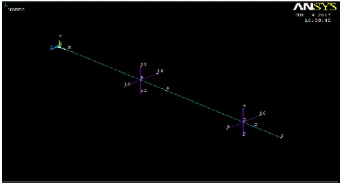
The entire length of the spindle is modelled as a Solid 10 Node 92 Element, whereas the bearings at the front and rear sides of the spindle are modelled using COMBIN 14 element is shown in Figure 6.
Fig -6: Finite element model of spindle for static deflection analysis
2.7 Boundary Conditions
[image:4.595.307.557.502.636.2]© 2015, IRJET ISO 9001:2008 Certified Journal Page 226 shown in Figure 7.The nodes at both the bearing sets are
constrained fully to have no degrees of freedom.
Fig -7: Finite element model of spindle with boundary conditions for static analysis
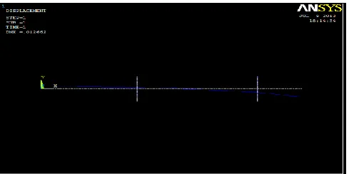
[image:5.595.39.285.138.264.2]5.8 Analysis Result
Fig -8: Finite element model of spindle with boundary
conditions for static analysis
The maximum deflection of the spindle obtained through ANSYS is found to be 12.66 microns as shown in Figure 8.As per the CMTI machine tool design handbook, the maximum deflection of shaft not exec 2e-4 times the span between bearings. In the present work of the spindle assembly the span length between bearing support is of 125 mm for which allowable static deflection works out to be 125 X 2e-4 =25 microns. Thus the maximum static deflection of 12.66 microns is will bellow the permissible value.
3. DYNAMIC ANALYSIS
Dynamic analysis can be used to determine the vibration characteristics (natural frequencies and mode shapes) of a structure or a machine component while it is being designed. It also can be starting point for another, more detailed, dynamic analysis, such as a transient analysis, a harmonic analysis, or a spectrum analysis. Dynamic
analysis is the study of the dynamic properties of structures under vibration excitation.
3.1 Mode Equations of Spindle
Based on a kinetic model of a vibration system, a mathematical model can be developed to accomplish the modal analysis. It is critical for modal analysis to develop the mathematical model. Accuracy degree of a model should affect analysis result directly. A general kinetic model is
[M] { (t)}+[C] { (t)}+[ K]{x(t)}= {F(t)} (4)
Where, [M] =Total mass matrix,
[C] = Equivalent damping matrix, [K] = Stiffness matrix,
X (t) = Displacement, F (t) = External load.
A model analysis equation of a spindle is shown as follows when an external exciting force is zero [F(t)=0] for characteristics of a spindle.
[M] {x(t)}+[C] {x(t)}+[ K]{x(t)}= 0 (5)
Equation (5) shows that vibration amplitude of a spindle should be attenuated during process of vibration.
3.2 Loading and Boundary Conditions
Zero-bond is the only load in the modal analysis. The front and rear bearing of the spindle taken for this study is fixed-end with constrains the degree of freedom of Ux, Uy, and Uz as shown in Figure 6.The rear bearing is constrained in the same way as the front bearing.
3.3 Mode shapes
[image:5.595.37.282.330.452.2]© 2015, IRJET ISO 9001:2008 Certified Journal Page 227
[image:6.595.317.559.640.754.2]Fig -9: Mode shape at natural frequency81.20Hz (Mode-1)
Fig -9: Mode shape at natural frequency105.9Hz (Mode-2)
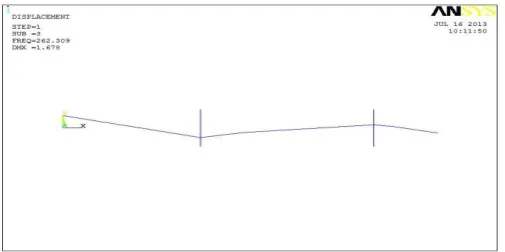
Fig -9: Mode shape at natural frequency262.3Hz (Mode-3)
Fig -9: Mode shape at natural frequency328.5Hz (Mode-4)
Fig -9: Mode shape at natural frequency452.3Hz (Mode-5)
3.4 Modal Analysis Result
Result summary of modal analysis of spindle for first six natural frequencies i.e., from Mode -1 to Mode -5 are listed in Table 4
Table -4: Result summary of modified modal analysis of spindle
SET FREQUENCY,Hz
1 81.20
2 105.9
3 262.3
4 328.5
5 452.3
The first mode frequency (81.20 Hz) is beyond the operating frequency (66.6 Hz) which would not cause any resonance of the spindle.
4 VIBRATION MEASUREMENT TEST
© 2015, IRJET ISO 9001:2008 Certified Journal Page 228 Fig -10: Experimental setup
[image:7.595.44.280.306.389.2]
Fig -11: Vibration severity level of spindle on LCD
TABLE -4: Vibration severity level of spindle
[image:7.595.47.278.408.583.2]
TABLE -5: Vibration severity per ISO 10816
Measurement point
Speed in rpm
Vibration severity
level in mm/sec
(rms)
Angle in degree
Motor drive end
2000 0.0067 67
3000 0.0089 147
4000 0.0102 220
4000 0.0109 84
4070 0.0110 61
By running the spindle between the speed 2000 r/min to 4070 r/min, the vibration severity level at the measurement point –motor drive end is shown in Table 7.3 seems to be within range of class 1 of industrial standard as per ISO 10816 is shown in Table 5.
5. CONCLUSIONS
In this work initially the BT-30 CNC Milling spindle has been designed and developed to satisfy the required specifications. Cost of the spindle has been reduced by proper selection of bearings for a speed of 4000rpm.Two dimensional static deflection analysis of the spindle
assembly by using BEAM3 and COMBIN14 element in ANSYS software has yielded the maximum vertical static deflection of 12.66 microns. This is close to theoretically calculated values of deflection. These values are within safe limit as per industrial standards detail as shown in Table 6.
Table-6: Comparison of theoretical and ANSYS deflection
values
Theoretical deflection in µ ANSYS deflection in µ
12.84 12.64
Modal analysis performed by using the ANSYS software helped in obtaining natural frequencies and their mode shapes. The frequencies obtained are shown in Table 4. And Spindle vibration levels were measured in the speed range of 2000 – 4000 r/min and the vibration instruments recorded both at the driving and non driving end of the spindle are within the two limits as specified in Class-1 ISO 10816 standard.
REFERENCES
[1] Harry peck, “designing for manufacturing”, pitman Publishing Corporation, and 1973.
[2] CMTI Machine tool design handbook, Tata McGraw-Hill, 1982.
[3] NTN Precision Bearing Catalogue, NTN make.
[4] Push-av, Soviet Engg Research, “Optimisation of plain bearing spindle assemblies”, 1987
[5] Yang shuzi, Intjmtdr, “study of the static stiffness of machine tool spindles”,
[6] Ansys White Paper, Leveraging the Design Chain,
www.ansys.com