© 2016, IRJET ISO 9001:2008 Certified Journal Page 1282
Performance analysis of 2D Multi-diagonal code for OCDMA system
Hargun Singh
1, Anu Sheetal
2, Maninder Singh
31
Research scholar, Department of Electronics Technology, Guru Nanak Dev University, Regional Campus,
Gurdaspur, Punjab, India
2,3
Assistant Professor in Department of Electronics Technology, Guru Nanak Dev University, Regional Campus,
Gurdaspur, Punjab, India
---***---Abstract
A new two dimensional codes family, namely two dimensional multi-diagonal (2D-MD) codes, is proposed for spectral/spatial non-coherent OCDMA systems based on the one dimensional MD code. Since the MD code has the property of zero cross correlation, the proposed 2D-MD code also has this property. So that, the multi-access interference (MAI) is fully eliminated and the phase induced intensity noise (PIIN) is suppressed with the proposed code. Code performance is analyzed in terms of bit error rate (BER) and the Q-factor. The performance of 2D-MD code is observed at different data rates from 1Gbps to 5Gbps. It is observed that the system performance decreases as the distance and number of simultaneous users increases. The 2D-MD code is evaluated in terms of BER, eye diagram and varied fiber length using RZ modulation format. Moreover, a large number of simultaneous users can be accommodated at low BER and high data rate.Key Words:OCDMA, MD, PIIN, MUI, DCF,FBG
1. INTRODUCTION
The OCDMA technique enables many subscribers to share the optical network resources simultaneously and asynchronously by allocating a specific code to each subscriber. The primary feature of the OCDMA technique is the simplification of the optical network, which provides high-bandwidth efficiency at a low cost. Multiple Access Interference(MAI), is considered as the dominant degradation factor in the OCDMA system [1-3]. According to the detection, the OCDMA system can be classified into coherent and non coherent system. Many schemes are used with the non coherent. OCDMA such as, the time spreading frequency hopping, spatial code, and spectral amplitude code(SAC). For the OCDMA scheme to be more realistic, it is desired to devise an optical code that can accommodate a larger number of simultaneous users with a low error probability for a given code length [4]. In the last decades, various optical spreading sequences for OCDMA networks have been investigated and experimented. However, we only focus our attention on 2 D codes. By increasing the length of 1D code, the properties of the codes can be improved. But for a given chip width, the length of the code grows rapidly as
the number of codes/weight of the code is increased and then the bit rate decreases. To overcome this problem 2 D codes have been reported [5,6]. Moreover, the limit of 1-D optical codes is that out of phase autocorrelation cannot be zero because there are multiple optical pulses within one period. The lower limit of out of phase autocorrelation in the 1-D codes is 1, and to achieve it as in the OOC, code length increases rapidly as the number of users increases. To overcome the limit of the 1-D optical codes, 2-D approaches are proposed [7]. In the 2-D optical codes, optical pulses are spread in both wavelength and time domains. By employing another dimension (wavelength), 2-D code with single pulse per row is achieved and the performance of the 2-D OCDMA system is much improved in comparison to the 1-D OCDMA system. Out-of-phase auto correlation and cross correlation of 2-D code families are equal to 0 and 1, respectively [8,9]. 2D-OCDMA codes have been proposed to solve the long code length for simultaneous user access, and keep good autoand cross-correlation. Although the encoder/decoder design will be more complicated, yet it will be suitable for a large number of users and will preserve more bandwidth for more users. 2D OCDMA codes usually consist of two OCDMA codes combined in one code, or by combining two domains of CDMA techniques. Examples include time spreading frequency hopping and frequency space time space schemes [10].
In [10], Z. Wei et al. proposed the MQC code for the SAC-OCDMA system with in phase cross correlation (IPCC) is equal one to mitigate the effect of MAI and PIIN.
© 2016, IRJET ISO 9001:2008 Certified Journal Page 1283 In [14], kadhim et al. present a new two dimensional codes
family, namely two dimensional multi-diagonal (2D-MD) codes, is proposed for spectral/spatial non-coherent OCDMA systems based on the one dimensional MD code.
In [15],Yeh et al. proposed the 2D-DPD codes which depend on one dimensional perfect difference code and the dilution method with fully elimination of the MAI. The dilution in spatial code is better than the dilution in spectral code. This paper is organized as follows, Section 2 describes the construction of the 2D-MD codes. Section 3 presents the architecture of the transmitter and receiver of the proposed code. The numerical results and discussions are presented in Section 4. Finally, the conclusions are drawn in Section 5.
2. 2D-MD code construction
The 2D-MD code can be constructed based on the MD code. The MD code is characterised by the following parameters L, m, ƛc .where,
N is the code length i.e. total number of chips, w is code weight i.e. the chips that have a value of 1 ƛc is the in phase correlation.
For the code sequence A = { a1, a2, a3,…,an } and B = { b1, b2, b3,…,yn } the cross correlation function can be represented by
(1)
When ƛc = 0 it is considerd that code possesses the zero cross correlation properties.The MD code consists of a K x N matrix functionally depending on the value of the number of users (U) and code weight (m). The choice of weight value is free and L = Um.
The MD code can be constructed as follows [14] : Firstly, a sequence of diagonal matrices is constructed by using a positive integer value of w and K. According to these values i,j will be set. Where (i = 1,2,3,…., U) is the index of rows in each matrix, and (j = 1,2,3,…,m) represents the number of diagonal matrices.
Secondly, based on the following equations the MD sequences are computed for each diagonal matrix
(2)
(3)
Each element of the Vi, j matrices represents the position of one in Wi, j matrices with K x K dimensions. When
(4)
(5)
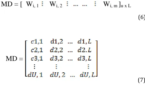
Thirdly,by the combination of diagonal matrices in (5), the MD codes are constructed as a matrix of dimension U x L,where each row in a matrix represents a single code sequence.
(6)
(7)
An example of the MD code family with U = 5 and m = 4 is presented in Table 1.
[image:2.595.314.558.431.577.2]
Table 1: MD code with ( U = 5, m = 4 )
ƛ
c=
V
i, j=
V
i, 1=
, V
i, 2=
, V
i, j=
, V
i, m=
W
i, 1=
, W
i, 2=
, …,W
i, w=
W
i, 1=
, W
i, 2=
,…..,
W
i, m=
MD = [ W
i, 1W
i, 2W
i, m]
u x L© 2016, IRJET ISO 9001:2008 Certified Journal Page 1284 The 2D-MD codes are extended from the 1D-MD codes and
can be constructed by using two code sequence of the 1D-MD codes.
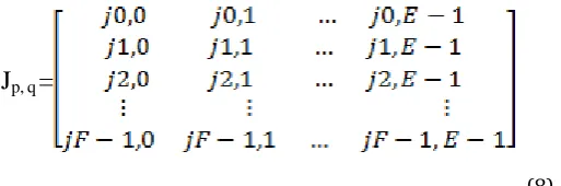
Let A = { a0, a1, a2,…., aE – 1 } with code weight m1 and B = { b0, b1, b2,…., bF – 1 } with code weight m2, represents two 1D-MD codes which has the code sizes u1 and u2 respectively. So that the code lengths of X and Y are E = u1 m1 and F = u2 m2 respectively.The code size of 2D-MD code is U = u1 u2. Let Xp and Yq are pth and qth code sequence of X and Y respectively,where p = 0,1,….,u1 – 1 and q = 0, 1,….,u2 – 1, which are spectral and spatial codes sequence respectively.The 2D-MD code can be expressed as Jp, q = BWq Ap. Let Ji, j represent the elements of Jp, q , where i = 0, 1,…,F -1 and j = 0,1,…,E – 1. Then Jp, q can be expressed as in eq(8). An example of the 2D-MD code sequence for ( m1 = 2, u1 = 4, m2 = 2, u2 = 3 ) is presented in Table 2.
(8)
The cross correlation of J00,0 and Jp, q can be expressed as follows [14] :
(9)
3. System Description
[image:3.595.33.290.299.384.2]There are u1u2 pairs of transmitters/receivers in which each pair uses the2D-MD codeword Jp. q and a F star couplers. Fig. 1a shows the structure of the transmitter which consists of an incoherent light source, an electrical to optical modulator(EOM) to convert the data bits from electrical form to optical form, an optical splitter for spatial coding and two sets of fiber brag grating FBG1 and FBG2 where they have the same number of gratings but with opposite arrangement used for spectral coding and run trip delays compensation respectively. The incoming data bits firstly modulated by the EOM in accordance with the ON– OFF keying format, where the electronic signals are converted into optical pulses The modulated optical pulses are delivered to the FBG1 to encode it spectrally according to the spectral code sequence Ap. Where the spectral components with wavelengths matched to “1” of a code sequence are reflected back and the others are filtered out, the reflected spectral components are delivered to the FBG2 to compensate the run trip delay. Later, these optical pulses are reach the optical splitter which are split into u2 equal parts in order to send it to the star couplers according to the code sequence of Bq. At this stage, the optical signal is fully encoded in two dimensions. The structure of the receiver is shown in Fig. 1b, which comprises one combiner, direct detector and an integrator.
Table 2: 2D-MD code with ( m1 = 2, u1 = 4, m2 = 2, u2 = 3 )
G
(0)(p, q) =
a
(0)i, j, a
i, j(p, q) =
J
p, q=
© 2016, IRJET ISO 9001:2008 Certified Journal Page 1285 The incoming optical signals from the star couplers are
summed up by the combiners according to the code sequence Bq. Each direct detector consists of two sets of fiber brag grating (FBGs), two circulators, and one photodiode(PD). FBG1 is used to reflect back the same
spectral components which are matched to “1s” of the spectral code sequence Ap. FBG2 have the same gratings but in opposite direction to compensate the run-trip delays. Finally the aggregated signal is filtered by the low pass filter (LPF).
.
Fig. 1: (a) The transmitter of presented system and (b) the receiver of the presented system
4. Results and Discussion
The performance analysis of 2D-MD code is carried out with various performance matrices such as (i) comparison of fiber length with BER, (ii) comparison of number of simultaneous active users with the Q-factor. Here fiber length is varied from 1 to 50 km, number of users are varied from 2 to 12. Also bit rate is varied from 1Gbps to 5Gbps, keeping input power 0dBm. All the results are carried out in optisystem software.
0 10 20 30 40 50
10-300 10-250 10-200 10-150 10-100 10-50 100
Fiber length [km]
B
E
R
[
d
B
]
1Gbps 2.5Gbps 5 Gbps
[image:4.595.52.548.196.521.2]© 2016, IRJET ISO 9001:2008 Certified Journal Page 1286
2 4 6 8 10 12
35 40 45 50 55 60 65 70 75 80 85
Number of users
Q -F a c to r 1Gbps
Fig.3: Number of active users v/s Q-factor
Fig.2 indicates the variation of BER with the fiber length, as the fiber length increases, the BER also increases. This is because the strength of signal decreases with distance, so inline amplifiers and dispersion compensation fiber(DCF) is used to enhance the system performance. The results are carried at different data rates as shown in Fig.2 such as 1Gbps, 2.5Gbps and 5Gbps. It can be seen that as the data rate increases, BER value increases i.e. system performance degrades. At 1Gbps optimum results are obtained. Fig.3 shows the variation of Q-factor with the number of simultaneous active users at 1Gbps. As the number of users increases the value of Q-factor decreases. This is because the input power from the light source divide between different users, as the number of users increases the power delivered to each user decreses, which results in the degradation in the system performance.
5. CONCLUSIONS
In this paper, a two dimensional code referred to as 2D-MD code was proposed for spectral/spatial non coherent OCDMA system. The construction of this code based on the 1D-MD code. The performance of the OCDMA system with the 2D-MD code has been evaluated at different data rates. The optimum results are obtained at 1Gbps data rate.The system performance decreases as the distance and number of simultaneous users increases The numerical results for the 2D-MD code shows that this code can significantly reduce the effect of noise and give a low bit error rate with more active users.The system with the proposed code is validated by using the simulation software, which makes the proposed code applicable in the practical system.
REFERENCES
[1] P.S. Menona, Ali Z. Ghazi Zahida, J.S. Mandeepb, S. Shaari, “ Realization of 2-D OCDMA network using EDW code,” Optik 123 (2012) 1385– 1389.
[2] M. Ravi Kumara, P. Ganguly, S.S. Pathak, N.B.
Chakrabarti, “Construction and generation of OCDMA code families using a complete row-wiseorthogonal pairs algorithm,” International Journal of Electronics and Communications (AEÜ), 67 (2013) 868– 874.
[3] Rasim Azeez Kadhim, Hilal Adnan Fadhil, S.A. Aljunid,
Mohamad Shahrazel Razalli, “A new two dimensional spectral/spatial multi-diagonal code for noncoherent optical code division multiple access (OCDMA) systems,” Optics Communications 329 (2014) 28–33.
[4] Aarti Bhardwaj, Disha Srivastava, Manu Gangwar, Nidhi,
“Simulation and Analysis of 2D Wavelength/Time Addition Modulo Temporal Length (W/T AML) code for OCDMA System,” International Journal of Engineering Research & Technology (IJERT), Vol. 4 Issue 08, August-2015. [5] Vishav Jyoti, R.S. Kaler,” Design and implementation of
2-dimensional wavelength/time codes for OCDMA,” Optik 122 (2011) 851–857.
[6] H. Monga, R. S. Kaler, “Investigating Wavelength
Allocation and Suitable Modulation Format for 2D Wavelength/Time and 3D Wavelength/Time/Space Codes in Order to Enhance System Performance,” Journal of Communications Technology and Electronics, Vol. 59, No. 11, pp. 1180–1189, 2014.
[7] Vishal Mishra1 R.K. Chauhan, “Performance Analysis of
1D and 2D in Optical Code Division MultipleAccess,”
International Journal for Scientific Research &
Development| Vol. 2, Issue 06, 2014.
[8] Anita Borude, Shobha Krishnan,“Simulation of Optical CDMA using OOC codes,” International Journal of Scientific and Research Publications, Volume 2, Issue 5, May 2012.
[9] Vandana Nath , Nakul Jain, “ Performance Analysis of Various coding Techniques in Optical Code Division Multiple Access System,” International Journal of Emerging Technologies in Computational and Applied Sciences, vol. 4,no. 1, March-May 2013, pp. 77-82.
[10] Zou Wei, H.M.H. Shalaby, H. Ghafouri-Shiraz, “Modified
Quadratic congruence codes for fiber Bragg Grating based Spectral amplitude coding Optical CDMA systems,”Journal of Lightwave Technology, vol.19 issue 9, pp 1274 , 2001. [11] T.H. Abd, S.A. Aljunid, H.A. Fadhil,“ A new code design in spectral amplitude coding Optical CDMA systems using fiber bragg grating,” Journal of optics vol. 42 no. 2, pp 110-115, 2013.
[12] C.-C Yang, J.-F Huang, “ Performance analysis on hybrid MQC/M-Sequence coding over Frequency/Spatial optical CDMA System,” IEEE Photonics Technology Letters vol1. 55, no. 1, pp 168, 2003.
[13] C.H. Lin , J. Wu, “ Comments on Novel Combinatorial Constructions of optical Orthogonal codes for Incoherent Optical CDMA Systems,” IEEE Journal of Lightwave Technology, vol. 24, no. 2, pp. 1064, Feb. 2006.
[14] Rasim Azeez Kadhim, Hilal Adnan Fadhil, S.A .Aljunid,
© 2016, IRJET ISO 9001:2008 Certified Journal Page 1287
code division multiple access systems,
OpticsCommunications vol. 329 pp. 28–33, 2014. [15] B.C. Yeh, C.H. Lin, C.L. Yang, J. Wu, “ Non Coherent