© 2016, IRJET ISO 9001:2008 Certified Journal
Page
2182
The Performance Analysis Of Four Tank System
For Conventional Controller And Hybrid Controller
Parvathy Prasad
11
PG Scholar,Vimal Jyothi Engineering College,chemberi,Kannur
---***---
Abstract
- Design of multivariable control system is veryessential in the process industries. The four tank system is a benchmark system. So disturbances are essential to analyze the performance of various controllers. Steady state analysis and linearization done using mathematical operations. Mathematical modeling of system is done using first principle. Here the performance of the system in non minimum phase is analyzed for conventional PI controllers and hybrid fuzzy PI controller. Servo and regulatory response of both of the controllers analyzed .It is found that hybrid fuzzy PI controller controls the system effectively than conventional controller.
Key Words: four tank system, MIMO system,
Conventional controller, hybrid fuzzy PI controller, Fuzzy logic controller
1.INTRODUCTION
Industrial control problems are usually non-linear in nature and have multiple control variables. The systems involved in such industrial process show significant uncertainties, non-minimum phase behaviour and a lot of interactions. To understand the non-idealities of such industrial processes there is a need for laboratory equipment to carry out experiments. The quadruple tank system is a benchmark system used to analyse the nonlinear effects in a multivariable process[1]. This helps in realizing the multi loop systems in industries. It is a level control problem based on four interconnected tanks and two pumps. The inputs to the process are the voltage to the pumps and outputs are the water levels in the lower two tanks. Many times the liquid will be processed by chemical or mixing treatment in the tank, but always the level of fluid in the tank must be controlled and the flow between tanks must be regulated[2].
The Quadruple tank was developed in the 1996 at Lund institute of Technology, Sweden in order to illustrate the importance of multivariable zero location for control design[3]. The quadruple tank process is thus used to demonstrate coupling effects and performance limitations in multivariable control systems. The multivariable dynamic property in a quadruple tank system is the way in which each pump affects both the outputs of the system. The quadruple tank system is widely used in visualizing the dynamic interactions and non- linearities exhibited in
the operation of power plants, chemicalindustries and biotechnological fields [4].The control of such interacting multivariable processes is of great interest in process Industries. Multivariable system involves a number of control loops which interact with each other where one input not only affects its own output but also influences other outputs of the system[5].
The performance of the four tank system for conventional PI and I controller was very effective[6].The system performs well for PID controller also[7],[8].It has been discussed in various papers. The system is suitable for the analysis of some advanced controllers also. It is possible to control the quadruple tank system using Fuzzy logic PI controllers[8].The four tank system provides better result for the interval type -2 fuzzy logic controller(IT2FLC)[9].There were some studies to design a decentralized Fuzzy pre compensated PI controller for multivariable laboratory quadruple tank system[10].Some papers describes the implementation of model based methods for the control of interacting four tank systems[11].FMMRAC is proposed and applied to the four tank system to test its effectiveness[12].Simple Fuzzy logic controllers can provide better control of the Quadruple tank system[13],[14]. Here mathematical modelling of the system done by applying first principles ,Taylor series and Jacobian matrix transformations[15].Quadruple tank system used for analysis of conventional PI controller and hybrid PI Fuzzy controller.
In this paper section 2 and 3 describes the quadruple tank system and modelling respectively. Section 4 contains the design of controllers and 5 is simulation analysis. Section 6 is the conclusion
2. FOUR TANK SYSTEM
© 2016, IRJET ISO 9001:2008 Certified Journal
Page
2183
The action of pumps 1 and 2 is to suck water from the reservoir and deliver it to tanks based on the valve opening. Pump 2 delivers water to tank 2 and tank 3. Similarly the pump 1 delivers water to tank 1 and tank 4. The system aims at controlling the liquid levels in the lower tanks. The controlled outputs are the liquid levels in the lower tanks (ℎ1, ℎ2). The valve positions are 𝛾1 and 𝛾2. These valve positions give the ratio in which the output from thepump is divided between the upper and lower tanks. The valve position is fixed during the experiment and only the speed of pump is varied by changing the input voltages to the pumps. Flow of the liquid can be seen using a rotameter.
Fig- 1: Quadruple Tank System
The operation of quadruple tank system can be in two phases minimum phase and non- minimum phase. It is seen from the Fig.1 that the output of tank 1 is influenced by tank 3 and the position of valve 1. The output of tank 2 is influenced by tank 4 and also by the position of valve 2. When the fraction of liquid entering the lower tanks is less than that of upper tanks then the system starts operating in non minimum phase. When the fraction of liquid entering the upper tanks is less than that of lower tanks then the system starts operating in minimum phase.
3. MODELLING
Here we are representing the system in terms of a set of mathematical equations, whose solutions gives the dynamic behavior of the system.
Initially we write the mass balance equations using Bernoulli’s law.
𝐴𝑑ℎ𝑖
𝑑𝑡 = 𝑞𝑖𝑛 𝑖 − 𝑞𝑜𝑢𝑡 𝑖 (1)
Each pump i=1, 2 gives a flow proportional to the control signal as follows
𝑞𝑖𝑛 𝑖= 𝑘𝑖𝑣𝑖𝛾 for i=1,2 (2)
𝑞𝑖𝑛 𝑖 =𝑘𝑖𝑣𝑖(1 − 𝛾) for i=3,4 (3)
Where 𝑘𝑖 is the pump constant. Considering the flow in and out of all tanks simultaneously, the non-linear dynamics of the quadruple tank process is given Where 𝐴𝑖 denotes the cross sectional area of the tank, hi is the water level, 𝑞𝑖𝑛 𝑖 is the in-flow of the tank and 𝑞𝑜𝑢𝑡 𝑖 is the out-flow of the tank.
𝑞𝑜𝑢𝑡 𝑖 = 𝑎𝑖 2𝑔ℎ𝑖 (4)
Where 𝑎𝑖 denotes the cross-sectional area of the outlet hole, g is the acceleration due to gravity
Final equations are
𝑑ℎ1
𝑑𝑡 = − 𝑎1
𝐴1 2𝑔ℎ1+ 𝑎3
𝐴1 2𝑔ℎ3+ 𝛾1𝑘1
𝐴1 𝑣1 (5)
𝑑ℎ2
𝑑𝑡 = − 𝑎2
𝐴2 2𝑔ℎ2+
𝑎4
𝐴2 2𝑔ℎ4+
𝛾2𝑘2
𝐴2 𝑣2 (6)
𝑑ℎ3
𝑑𝑡 = − 𝑎3
𝐴3+
(1−𝛾2)𝑘2
𝐴3 𝑣2 (7)
𝑑ℎ4
𝑑𝑡 = − 𝑎4
𝐴4 2𝑔ℎ4+
(1−𝛾1 )𝑘1
𝐴4 𝑣1 (8)
Non linear relationship in the equation is due to square root term present in it. The equation is solved using Taylor series followed by Jacobian matrix transformation to obtain a state space form of quadruple tank process[15].
A= −1 𝑇1 0
𝐴3 𝐴1𝑇3 0
0 −1
𝑇2
0 𝐴4
𝐴2𝑇4
0 0
0 0
−1 𝑇3 0
0 −1
𝑇4
(9)
B= 𝛾1𝑘1
𝐴1 0
0 𝛾2𝑘2
𝐴2
(1−𝛾01)𝑘1 𝐴4
(1−𝛾2)𝑘2
𝐴3
0
(10)
C=𝑘𝑐 0 0 0
0 𝑘𝑐 0 0 (11)
© 2016, IRJET ISO 9001:2008 Certified Journal
Page
2184
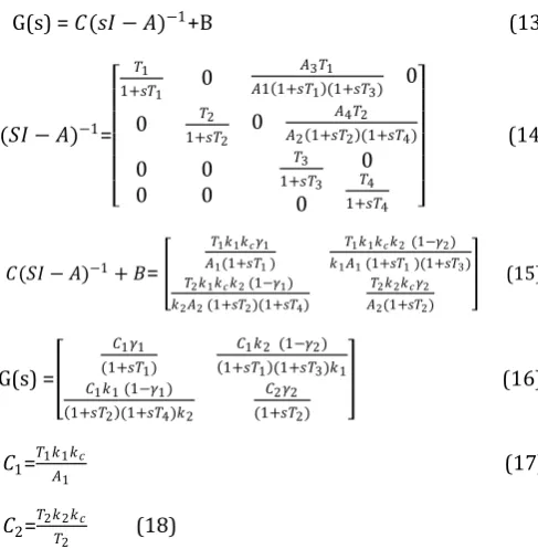
State space model can be converted to transfer function model by using a simple conversion technique.
G(s) = 𝐶(𝑠𝐼 − 𝐴)−1+B (13)
(𝑆𝐼 − 𝐴)−1= 𝑇1
1+𝑠𝑇1 0
𝐴3𝑇1
𝐴1 1+𝑠𝑇1 (1+𝑠𝑇3) 0
0 𝑇2
1+𝑠𝑇2 0
𝐴4𝑇2
𝐴2 1+𝑠𝑇2 (1+𝑠𝑇4)
0 0
0 0
𝑇3
1+𝑠𝑇3
0 0
𝑇4
1+𝑠𝑇4
(14)
𝐶(𝑆𝐼 − 𝐴)−1+ 𝐵=
𝑇1𝑘1𝑘𝑐𝛾1 𝐴1(1+𝑠𝑇1 )
𝑇1𝑘1𝑘𝑐𝑘2 (1−𝛾2) 𝑘1𝐴1 (1+𝑠𝑇1 )(1+𝑠𝑇3) 𝑇2𝑘1𝑘𝑐𝑘2 (1−𝛾1)
𝑘2𝐴2 (1+𝑠𝑇2)(1+𝑠𝑇4)
𝑇2𝑘2𝑘𝑐𝛾2 𝐴2(1+𝑠𝑇2)
(15)
G(s) =
𝐶1𝛾1
(1+𝑠𝑇1)
𝐶1𝑘2 (1−𝛾2)
1+𝑠𝑇1 (1+𝑠𝑇3)𝑘1
𝐶1𝑘1 (1−𝛾1)
1+𝑠𝑇2 (1+𝑠𝑇4)𝑘2
𝐶2𝛾2
(1+𝑠𝑇2)
(16)
𝐶1= 𝑇1𝑘1𝑘𝑐
𝐴1 (17)
𝐶2= 𝑇2𝑘2𝑘𝑐
𝑇2 (18)
[image:3.595.37.281.130.379.2]
Table -1: System Parameter Values
Parameter(Unit) Value
𝐴1, 𝐴3[c𝑚2] 28
𝐴2,𝐴4[𝑐𝑚2] 32
𝑎1,𝑎3[𝑐𝑚2] .071
𝑎2, 𝑎4[𝑐𝑚2] .057
𝑘𝑐 1
g 981
ℎ1 10.43
ℎ2 15.98
ℎ3 6.60
ℎ4 9.57
𝑣1 3.15
𝑣2 3.15
𝑘1 3.14
𝑘2 3.29
𝛾1,𝛾2 .35
G(s)=
2.26 (57.74𝑠+1)
2.91 57.74𝑠+1 (38.14𝑠+1) 3.61
88.34𝑠+1 (56.47𝑠+1)
3.17 (88.34𝑠+1)
(19)
4.
.DESIGN OF CONTROLLERS
4.1 PI CONTROLLER
PI controller is a conventional controller widely used in industries. It will eliminate forced oscillations and steady state error resulting in operation of on–off controller and proportional controller respectively.
It is generally used in the areas where speed of the system is not an issue. Here we are using two PI controllers for controlling two tanks. Tuned values for both Kp, Ki are given in the table.
Table 2-Tuned values of PI controller
PI controller
Kp Ki
PI1 -0.042871 -0.001319
PI2 0.610421 0.02343
4.2 FUZZY PRE COMPENSATED PI CONTROLLER
Here fuzzy methods are used to enhance the performance of system using PI controller. Basic configuration of FPPIC is shown in the figure.FLC has just a supplementary role to enhance the existing control system when control conditions changes. When disturbance acting on the system ,the performance of PI controller become poor. The replacement or tuning of existing controller may provide better results. But this is not possible all the time. So FLC used to provide a modified control action to existing PI controller.
Fig-2: Basic configuration of FPPIC
© 2016, IRJET ISO 9001:2008 Certified Journal
Page
2185
pump voltages(𝑣1,𝑣2) are the controller outputs. The error and change in error is converted into seven linguistic values namely NB, NM,NS,ZR,PS,PM and PB. Similarly controller output is converted into seven linguistic values
namely NB,NM,NS,ZR,PS,PM and PB. Triangular
membership function is selected and the elements of each of the term sets are mapped on to the domain of corresponding linguistic variables. The membership functions for error change in error and controller output is shown in the figure.
Fig -3: Membership function of error and change in error
Fig-4: Membership function of controller output
Table-3:Rulebase for the fuzzy logic compensator
Basically, the decision logic stage is similar to a rule base consisting of fuzzy control rules to decide how FLC works. The rules are generated heuristically from the response of the conventional controller , 49 rules are derived for each fuzzy controller from careful analysis of trend obtained from the simulation of conventional controller and known
process knowledge. The rules are given in Table 3.The decision stage processes the input data and computes the controller outputs. The output of the rule base is converted into a crisp value, this task is done by defuzzification module.
5. SIMULATION ANALYSIS
The performance of the system for PI controller and Fuzzy pre -compensated PI controller can be analyzed easily from the simulation results
Chart -1: Regulatory response of the system for tank 1
Chart-2:Servo response of the system for tank 1
0 500 1000 1500 2000 2500 3000
-5 0 5 10 15 20 25 30
Time(s)
L
e
v
e
l
o
f
ta
n
k
1
(c
m
)
Response of FPPIC Response of PIC Setpoint
0 500 1000 1500 2000 2500 3000 3500 4000 4500 5000
0 2 4 6 8 10 12 14 16 18 20
Time(s)
L
e
v
e
l
o
f
Ta
n
k
1
© 2016, IRJET ISO 9001:2008 Certified Journal
Page
2186
Chart-3: Servo response of the system for tank 2
Chart-4: Regulatory response of the system for tank 2
It is clear from the results that the hybrid controller provides less steady state error and fast settling compared to conventional controller.
Table-3:Analysis of Performance indices
Perf orm ance
indic es
Tank 1 Tank 2
PI
serv o
FPPI
servo PI
regu lato ry
FPPI
regul ator
y PI
Servo FPPI
servo PI
regula tory
FPPI
regu lator y
ITAE 2675 1327 187
5
1012 2533 352 1013 122
ISE 277 106 276
2
118 604 199 2762 1668
The performance of the two controllers can be evaluated using performance indices namely Integral Square error (ISE) and Integral Absolute Error (IAE). A control system is considered optimal when it minimizes the above integrals. Table 4 summarizes the integral error values for the two control schemes. Fuzzy pre compensated PI controller has the least ISE, and IAE values.
3. CONCLUSIONS
This work clearly shows the advantages of using fuzzy pre compensated PI controller for a Four Tank System. The comparison of the two controllers reveals that fuzzy pre compensated PI controller performs well for the system.
REFERENCES
[1] Prof. D. Angeline Vijula, Anu K,Honey Mol P, PoornaPriya “Mathematical Modelling of Quadruple Tank System”, International Journal of Emerging Technology and Advanced Engineering ,Volume 3, Issue 12, December 2013
[2] Jaya prakash J, Davidson D, Subha Hency Jose P, “Comparison of Controller Performance for MIMO Process”, International Journal of Emerging Technology and Advanced Engineering, Volume 3, Issue 8, August 2013
[3] Johansson KH, Horch A, Hansson A. “Teaching multivariable control using the quadruple tank process”. In: Proceeding of the 38th conference on decision & control; December 1999.
[4] Qamar Saeed, Vali Uddin and Reza Ketabi “ Multivariable predictive PID control for quadruple tank”, in Proceedings of World Academy of Science, Engineering and Technology, Beijing, China, Vol.67, No.4, pp.861-866.
0 500 1000 1500 2000 2500 3000
2 4 6 8 10 12 14 16 18
Time(s)
L
e
v
e
l
o
f
ta
n
k
2
(c
m
)
Response of PIC
Response of FPPIC Setpoint
0 500 1000 1500
0 5 10 15 20 25
Time(s)
L
e
v
e
l
o
f
ta
n
k
2
(
c
m
)
© 2016, IRJET ISO 9001:2008 Certified Journal
Page
2187
[5] Jayaprakash J, SenthilRajan T, Harish Babu T,“Analysis of Modelling Methods of Quadruple Tank System”, International Journal of Advanced Research in
Electrical Electronics and Instrumentation
Engineering, Vol. 3,Issue 8, August 2014
[6] Yousof Gholipour, Ahmad Zare, “Comparing the effect of PI and I controllers on a four tank process”, International Journal of Recent Research in Electrical and Electronics Engineering (IJRREEE) Vol. 1, Issue 1, pp: (1-6), Month: April - June 2014.
[7] W. Belhaj , O. Boubaker,“On MIMO PID Control of the quadruple-tank process via ILMIs Approaches : Minimum and Non-Minimum Case studies”,10th IFAC International Symposium on Dynamics and Control of Process Systems, The International Federation of Automatic Control ,December 18-20, 2013. Mumbai, India
[8] S.K.Lakshmanaprabu, N. Sivaramakrishnan, U. Sabura Banu, “Closed Loop Control of Quadruple Tank Process using Fuzzy Logic PI Controller”, National Conference on Computational Intelligence for the Engineering Quality Software (CiQS 2014)
[9] Karthick S, Lakshmi P, Deepa T, “Comparison of Fuzzy Logic Controllers For a Multivariable Process”, International Journal of Electrical and Electronics Engineering (IJEEE) ISSN):pp 2231 – 5284, Volume-3, Issue-1, 2013
[10] R.Suja Mani Malar , T.Thyagarajan, “Design of
Decentralized Fuzzy Pre compensated PI Controllers for Quadruple Tank system”.International Journal of Recent Trends in Engineering, Vol 2, No. 5, November 2009
[11] Edward Gatzke, Edward S. Meadows, Chung Wang,
Franc is J. Doyle III P, “Model Based Control Of a Four Tank System”, Computers and Chemical Engineering pp 1503-1509.
[12] ` Sankata B. Prusty, Umesh C. Pati and Kamala K.
Mahapatra, “A Novel Fuzzy based Adaptive Control of the Four Tank System”
[13] Shebeera C. A, Shijoh V, M. V. Vaidyan, “ Non-linear
Modeling and Fuzzy Control for a Quadruple Tank Process”, Proceedings of National Conference EEM 2014
[14] “Non-linear Modeling and Fuzzy Control for a
Quadruple Tank Process”, Proceedings of National Conference EEM 2014.
[15] R.SujaMani Malar,T.Thyagarajan,“Modeling of
Quadruple Tank System Using Soft Computing Techniques”,European Journal of Scientific Research ISSN 1450-216X Vol.29 No.2(2009),pp.249-264
[16] Jayaprakash J, SenthilRajan T, Harish Babu, “Analysis
of Modelling Methods of Quadruple Tank System” , Engineering International Journal of Advanced
Research in Electrical Electronics and
Instrumentation,Vol. 3, Issue 8, August 2014