2018 3rd International Conference on Computational Modeling, Simulation and Applied Mathematics (CMSAM 2018) ISBN: 978-1-60595-035-8
Simulation Calculation of Influence of DC Bias Suppression of
Grounding Electrodes on GIC of Hami Power Grid
Fan SUN
1, Xia-yao ZHAO
2,*, Lian-guang LIU
2, Yan-hui QIN
1and Peng ZHU
11
State Grid Xinjiang Electric Power Research Institute, Urumqi 830000, Xinjiang Uygur Autonomous Region, China
2School of Electrical and Electronic Engineering, North China Electric Power University,
Changping District, Beijing 102206, China
*Corresponding author
Keywords: DC magnetic bias suppression, GIC, Effect, Blocking devices.
Abstract. A lot of HVDC projects in China adopted capacitor blocking devices to suppression DC bias magnetic. This method will lead to a redistribution of the DC bias current and the geomagnetic induced current of the power grid, increasing the risk of geomagnetic storm hazards to the power grid. For the Tianshan grounding Electrode DC bias magnetic suppression of the Tianzhong HVDC project, the GIC model for 750 kV and 220 kV Hami grid was established. The GIC of grid before and after suppression was calculated using 1V/km geoelectric field and MATLAB programming. The impact of capacitor blocking devices on the GIC of 750 kV and 220 kV Hami grid was compared. The results show that the use of capacitor blocking devices to suppress the DC bias current of the grounding electrode will increase the GIC of some transformers of neighboring substations in the power grid, and the research methods and results are of great significance to the GIC suppression of power grid.
Introduction
The suppression of geomagnetic induced current (GIC) generated by geomagnetic storms on the grid has become a research topic[1,2]. After the power outage in Quebec on March 13, 1989[3], the North American Electrical Reliability Council (NERC) and other organizations carried out a lot of research on GIC suppression. The results show the method of installing series capacitors in transformer neutral to suppress GIC will increase the nearby transformers’ GIC [4]. This phenomenon also exists in China. It’s necessary to study the effect of suppression of grounding DC bias on the GIC. The higher the latitude and the smaller the DC resistance of the transmission line conductors, and the more serious the geomagnetic storm disaster in grid[5-7]. In view of the relatively high latitude of Hami, the DC bias of the Tianshan grounding electrode in Tianzhong UHVDC is suppressed by capacitor devices. The paper studies the impact of Tianshan grounding electrode magnetic suppression on the GIC of Hami power grid and proposes solutions.
Hami Power Grid DC Bias Magnetic Suppression
Overview of Hami Power Grid in 2018
In the paper, the 750kV and the 220kV grid in Hami in 2018 before and after the suppression are taken as the research object for calculation and analysis. 750kV and 220kV power grid in Hami in 2018 is shown in Figure 1. It contained 4 750kV substations and 4 750kV transmission lines. There are 33 220kV substations and 37 220kV transmission lines in Hami grid.
19
20 25 26 28 27
29
30
34 35
36 37
38 39 40 41
21 22
44
43
45 46
47
49 50
51 52
53 54 48 55
56 57 31
32 33
42
suppressed 750kVstations
unsuppressed 750kV stations
suppressed 220kV stations
[image:2.595.179.437.184.365.2]unsuppressed 220kV stations
Figure 1. 750kV and 220kV planning Hami power grid in 2018.
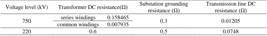
Calculating the GIC of Hami grid requires three sets of parameters which are shown in Table 1. Among them, 750kV substations adopt auto-transformers, and the DC resistance of series windings and common windings are the same as the value of the transformer of Hami 750kV substations. The rest of the parameters are calculated from the typical parameters of DC resistance in China [9].
Table 1. The parameters of substation, transformer and transmission line of each voltage level.
Voltage level (kV) Transformer DC resistance(Ω) Substation grounding resistance (Ω)
Transmission line DC resistance (Ω)
750 series windings 0.158465 0.3 0.01205 common windings 0.007935
220 0.6 0.5 0.0748
The number of transformers for the 750kV substations in Hami in 2018 is known, but that in the 220kV substations is unknown. Therefore, suppose that 220kV substations in Hami have two transformers, and all neutral points are grounded by the typical grounding resistance in Table 1.
Hami Grid DC Bias Magnetic Suppression
Hami Grid installs blocking devices at the neutral points of some 750kV, 220kV, and 110kV transformer substations. The suppressed substations of the grid include: 1)3 750kV substations: 19, 20, 22. 2)17 220kV substations: 31, 34, 36, 38, 39, 41, 43, 44, 45, 46, 50, 52, 53, 54, 55, 57, 56.
GIC Model of the Power Grid Considering DC Bias Magnetic Suppression
Geomagnetically Induced Electric Field
[image:2.595.63.532.472.535.2]the geomagnetic field and the geoelectric field is neglected, then the GIC calculation of grid is converted into a circuit problem.
At present, the layered earth resistivity model and the geomagnetic data of four geomagnetic
stations in the northwest in China from the geomagnetic storm (Kp=8) from November 9 to 10,
2004[12] were used to calculate the inductive geoelectric field. The literature[13]calculated the
geoelectric field peak value in Xinjiang of China caused by the geomagnetic storm E=0.9397V/km
with the east and the north component EE=0.3026V/km and EN=0.8896V/km respectively. Since this
geomagnetic storm is not the largest geomagnetic storm in the 22nd and 23rd solar weeks, this paper proposes to use a 1 V/km geoelectric field to calculate the GIC of the Hami grid. At the same time, this paper considers that the GMD induced geoelectric field is a uniform field, and according to the coordinate habit of the geophysical geoelectric field, two geoelectric fields with a size of 1V/km are to be established. This facilitates the calculation and synthesizes a GMD-induced geoelectric field of arbitrary orientation and size through an orthogonal electric field.
Induced Voltage Source
To calculate the GIC of grid, it is necessary to firstly equate the GMD-induced geoelectric field as an induced voltage on the transmission line system. Then set all the buses and neutral points of each substation as nodes, each transformer winding and line as a branch. Then a grid DC network model was formed. Finally, a conventional circuit method is used to solve the model [14].
The induced voltage acting on the transmission lines can be simplified calculated by
N N E E
U E L E L
(1)
In the equation(1), EN and EE are the northward and eastward geoelectric field values in V/km
respectively; LN and LE are the lengths of the transmission lines in the north and east directions in km
respectively. The calculation of LN and LE uses the method in [15].
The GIC model based on the GIC-Benchmark example is proposed in [14], and the GIC of grid for this standard example is calculated. The grids and transformer substations studied in this paper adopt autotransformer and three-phase transformer groups respectively. Each substation has more than one transformer. Therefore, the model of Hami grid can be established according to the method [14].
GIC Model of Power Grid
(a) (b)
(c) g
d
z z
g
g g
d
z z
g
g
g
d
z g
g
z
(d) g
d
z g
g
[image:3.595.210.386.510.695.2]z
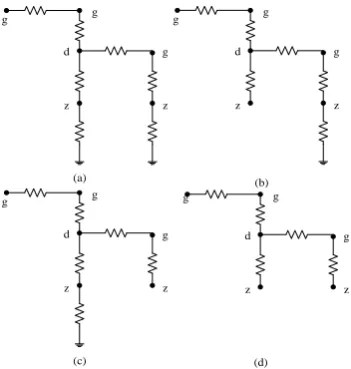
Figure 2. The grid model considering the blocking device.
Assume that the capacitors are put into operation when it is normal. Thus, in accordance with the characteristics of capacitor blocking, in the GIC model, the neutral point of the suppressed substation will be treated as an infinite DC resistance. The grid models before and after installation of the
blocking device are shown in Figures 2(a) and Figures 2 (b)(c)(d), respectively. Among them,
represents the high voltage winding, between d and z represents the intermediate voltage winding,
between z and the earth represents the grounding resistance, between g and z is the transformer
winding, and between the different voltage levels g and d is the transmission line.
Figure 2(a) shows the power grid model under two voltage levels when the blocking device is not added. Figure 2(b)(c)(d) respectively show a model of a power grid with capacitor blocking devices installed at transformer neutral points in substations with high voltage, low voltage, and two voltage levels. From figure 2(a) we can see that GIC can circulate through transmission lines and transformer windings without blocking devices. From we can see that after the high-voltage transformer neutral point is equipped with a capacitor blocking device, the GIC only circulates in the transmission line, high-voltage transformer high-voltage windings and low-voltage transformers. Figure 2(c) and 2(d) can be analyzed as figure 2(b).
Solution Method to the Model of GIC
In this paper, the node admittance matrix method is used to calculate the GIC of the Hami power grid
before and after the suppression of the grounding DC bias. Let i and k be any nodes in the network.
For the n-node network, the voltage equation for node can be written as
N
k ki k N
k ki i i
i N
k
ki u y u y u y
j
1 1
1
(2)
In the formula (2) , N is the number of nodes; jki represents the current flowing from the node k to
the node i; ui, uk represents the voltage of the node i and the node k; yki represents the line admittance.
Written in matrix form is
J=YU (3)
In the formula (3) , the matrix J is the n×1 order current source matrix, Jiis the sum of the current
sources connected to the node i; Y is the n×n order node admittance matrix.
The node voltage is
U=Y-1J (4) Then obtain each branch and transformer neutral point GIC by formula (5) (6).
k i
kiki
ki j u u y
i
(5)
i i i u y
i
(6)
The Effect of DC Bias Magnetic Suppression on GIC of Power Grid
The current flowing through the neutral point is the current value of three times the single-phase winding because the three-phase winding parameters of the transformer are the same. The result was represented by the three-phase value of the neutral point. This paper uses MATLAB software to calculate the GIC of the 750kV and the 220kV Hami grid before and after the suppression of Tianshan polar magnetic bias when the induced geoelectric fields are eastward and northward, respectively.
The Effect of 750kV Power Grid
The Effect of 220kV Power Grid
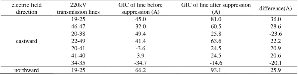
[image:5.595.50.546.225.351.2]A. Impact on 220kV Transmission Lines. Table 2 shows the GIC values of the 220kV transmission lines with GIC difference greater than 20A before and after suppression(excluding the line with GIC of zero after suppression) under the eastward and northward electric fields respectively, and their change values. The positive and negative GICs of the pre- and post-governance lines indicate that the actual current direction is the same as or opposite to the reference direction, which is shown in the second column of Table 2. The GIC difference of the grid is the numerical difference between the GIC before and after suppression.
Table 2. GIC of 220kV transmission line of Hami grid before and after suppression.
electric field direction
220kV transmission lines
GIC of line before suppression (A)
GIC of line after suppression
(A) difference(A)
eastward
19-25 45.0 81.0 36.0
46-47 32.0 60.5 28.6
20-38 49.4 25.8 -23.6
22-49 41.4 63.6 22.2
20-41 -3.6 24.5 20.9
41-40 3.9 24.5 20.6
34-35 -34.7 -14.6 -20.1
northward 19-25 66.2 93.1 25.9
Table 2 tells that in the eastward and northward electric fields, the 220kV lines with the largest change in GIC values before and after suppression is 19-25, with the difference being 36.0A and 25.9A, respectively. Due to the suppression of 19, 19-25 with the smallest line resistance is larger than the GIC of 19-20, while the latter is the longest 750kV line in Hami grid, which GIC is larger. It’s also concluded that not the 220kV line which directly connected to the 750kV substation has a larger change in GIC before and after suppression, which is different from our general perception. This is due to the suppressed stations is quite a lot.
B. Impact on 220kV Substation. Further analysis for comparison of the GIC of the 220kV substation in Hami grid before and after suppression in the eastward and northward electric fields is respectively shown in Figure 3(a) and 3(b).
[image:5.595.60.541.505.640.2]
(a) (b)
Figure 3. GIC of 220kV substations of Hami grid before and after suppression in the eastward and northward electric field.
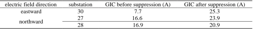
Table 3. GIC of the substation of neutral DC current exceeding standard after suppression.
electric field direction substation GIC before suppression (A) GIC after suppression (A)
eastward 30 7.7 25.3
northward 27 16.6 23.9
28 16.9 20.9
Table 3 shows the substations where the neutral point GIC exceeds the standard after suppression. According to the suppression standard, the maximum allowable current of the transformer neutral point of 220kV station is 18A, there is one in the eastward and two stations in the northward electric field meet the requirements before suppression, but don’t meet after suppression shown in Table 3. It can be seen that the suppression station has expanded the range of influence of the GIC on the transformer. The impact of the capacitor blocking device on GIC should be given enough attention to prevent this from being lost in separate suppression.
Conclusion
A. The changes before and after the suppression show regional characteristics. Suppression has less
impact on 750kV grid, but its converter station can become high-risk station because of the suppression.
B. Due to the suppressed stations in 220kV grid is quite a lot, it can concluded that not the 220kV
line which directly connected to the 750kV substation has a larger change in GIC before and after suppression, which is different from our general perception. And GIC of most 220kV stations which is not suppressed have increased.
C. The results of this paper show that the GIC of some stations transformers in the grid will increase
due to the use of capacitor blocking devices. And some transformers without GIC failure risk will become a faulty high-risk transformer. Thus, capacitor devices blocking should be try to avoid using to suppress DC magnetic bias currents.
Acknowledgement
The project was supported by National Natural Science Foundation of China (51577060) and National Key Research and Development Program (2016YFC0800100).
References
[1] C. M. Liu, J. C. Liu, X. Wang, Z. F Wang, X. D. Yang, An optimal layout method of capacitances and resistances for suppressing geomagnetically induced currents in power grid, J/OL. Power System Technology, (2018) 1-5.
[2] P.H. Yang, X. P. Zheng, L.G. Liu, C.M. Liu, C. L. Ma. Effects of transformer neutral grounding via small resistor on mitigating geomagnetically induced currents in power grid. Power System Technology. 41(04) (2017) 1324-1331. (in Chinese)
[3] J.G. Kappernman, V.D. Albertson. Bracing for the geomagnetic storms, J. IEEE Spectrum. 27(3) (1990) 27-33.
[4] J.G. Kappernman, S.R. Norr, G.A. Sweezy, et al. GIC mitigation: a neutral blocking/bypass device to prevent the flow of GIC in power systems, J. IEEE Transactions on Power Delivery, 6 (1991) 1271-1281.
[5] L.G. Liu, C.M. Liu, Zhang Bing. Effects of geomagnetic storm on UHV power grids in China, J. Power System Technology. 33(11) (2009) 1-5 (in Chinese).
[7] L.G. Liu, S.X. Guo, K.Wei, et al. State key laboratory of alternate electrical power system with renewable energy sources, J. Power System Technology. 38(7) (2014) 1946-1052.
[8] R. Horton, H. D. Boteler, R. Pirjola, et al. A test case for the calculation of geomagnetically induced currents, J. IEEE Transactions on Power Delivery. 27(4) (2012) 2368-2373.
[9] K. Zheng, L.G. Liu, H. Y. Ge, et al. Comparative study of the GIC amplitudes and characteristics in different power grids in China, C // CIGRE 2012 Session. Paris, France, (2012) 1-8.
[10] C. M. Liu, C. C. Huang, M. M. Pan, et al. Optimal configuration of capacitor blocking devices for suppressing DC bias in transformers, J. High Voltage Engineering. 42(7) (2016) 2308-2314.
[11] R. Pirjola, A. Viljanen. Complex image method for calculating electric and magnetic fields produced by an auroral electrojet of finite length, C//Annales Geophysicae. Springer-Verlag, 16(11) (1998) 1434-1444.
[12] C.M. Liu, Y.L. Li, R. Pirjola. Observations and modeling of GIC in the Chinese large-scale high-voltage power networks, J. Space Weather Space Clim. 4: A03(2014).
[13] C.M. Liu, Y.L. Li, L. Chen. Modelling geomagnetically induced currents in Xinjiang 750 kV power grid in China. In: IEEE Power and Energy Society General Meeting (PES). Vancouver BC, Canada, (2013). 1–5.
[14] K. Zheng, L.G. Liu, D.H. Boteler, et al. Modeling geomagnetically induced currents in multiple voltage levels of a power system illustrated using the GIC-Benchmark case, J. Proceedings of the CSEE. 33 (2013) 179-186.
[15] Horton R, Boteler D H, Overbye T, et al. A test case for the calculation of geomagnetically induced currents J. IEEE Trans on Power Delivery. 27 (2012) 2368-2373.
[16] V.D. Albertson, J.G. Kappenman, N. Mohan, et al. Load-flow studies in the presence of geomagnetically-induced currents, J. IEEE Transactions on Power Apparatus and Systems, 2 (1981) 594-607.
[17] Takasu N, Oshi T, Miyawaki F, et al. An experimental analysis of DC excitation of transformers by geomagnetically induced currents, J. IEEE Transactions on Power Delivery, 9(1994) 1173-1182.