2019 International Conference on Computer Science, Communications and Multimedia Engineering (CSCME 2019) ISBN: 978-1-60595-650-3
Energy Dissipation Method for Surrounding Rock's Stability
Analysis and Its Application
Jian-hua HE
1, Jian-hai ZHANG
2,*, Deng-yu LIU
2, Zhong ZHOU
1,
Cheng-gang LIAO
1and Can-can LUO
21Power China Chengdu Engineering Corporation Limited, Chengdu 610065, China
2State Key Laboratory of Hydraulics and Mountain River Engineering, College of Water Resources and Hydropower, Sichuan University, Chengdu 610065, China
*Corresponding author
Keywords: Underground powerhouse, Supporting structure, Total resistant energy, Dissipative energy, Energy dissipation ratio.
Abstract. Traditional single stress or strain failure criterion cannot fully consider the rock property of brittle-ductile transition, elasto-plastic finite element method is difficult to simulate the softening and instability of surrounding rock with low confining pressure, and reinforcement mechanism under complex stress state needs to be further studied for surrounding rock. From the energy storage and dissipation process of surrounding rock-support system, by establishing energy dissipation method (EDM) for surrounding rock's stability analysis and the energy supply theory of supporting structure, energy dissipation ratio criterion for surrounding rock's failure is proposed, and EDM calculation process for surrounding rock's stability analysis is given. With the analysis of surrounding rock's state and failure for Jinping I underground powerhouse, this paper particularly studies and compares the distribution rule of principal stress, total resistant energy and energy dissipation zone before and after reinforcement of surrounding rock. As a result, the deformation failure and supporting mechanism is expounded for surrounding rock, as well as verifying the feasibility of EDM.
Introduction
Excavation of underground powerhouse will release the restraint around its surrounding rock, causing rock mass originally at compressed state to produce a loosening deformation. And surrounding rock failure will occur when this deformation exceeds its own load-bearing limit, resulting in failure phenomenon such as splitting, spalling, bulging and relaxation [1, 2].
At present, numerical simulation often uses elasto-plastic incremental FEM (finite element method) to study deformation and stress distribution appeared in surrounding rock, and Mohr-Coulumb, Druker-Prager or other yield criteria based on stress state to study the failure zone of surrounding rock. However, rock properties after peak stress pressures are significantly different under various confining pressure [3-5]. Existing traditional failure criterion based on single stress or strain index cannot fully consider its characteristics of brittle-ductile transition, and explain the deformation failure mechanism of surrounding rock. Besides, conventional elasto-plastic FEM is difficult to simulate the softening characteristics of surrounding rock with low confining pressure, and it cannot consider the residual strain for ultimate state. So this method is unable to effectively reflect the entire process of softening and instability for surrounding rock.
A further point is that supporting structure composed of ordinary or pre-tensioned bolts, is usually adopted to reinforce surrounding rock in underground powerhouse to ensure its working stability. But due to various environmental conditions, such as high geo-stress, large burial depth, changeable strata crossing and dense spatial arrangement of cavern groups, reinforcement mechanism under complex stress state is not mature yet for supporting structure [6], requiring further study.
rock system [7-10]. And the supporting structure reinforcing surrounding rock, is regarded as a cooperative structural system and can produce energy effect on rock. Based on energy dissipation theory, energy dissipation method (EDM) for surrounding rock's stability analysis is established, together with the theoretical analysis method of energy supply for supporting structure, including an energy dissipation ratio criterion of rock failure and EDM calculation process based on FEM. Then taking Jinping Ⅰ underground powerhouse as a research object, its surrounding rock's state and failure situation are analyzed. By comparing and studying the distribution rule of main stress, total resistant energy and energy dissipation area before and after reinforcement in surrounding rock, the deformation failure and supporting mechanism of surrounding rock are further expounded, so as to verify the feasibility and practicability of EDM.
Rock Stress-strain Characteristic and Basic Theory of Energy Dissipation
Essential Features of Rock Stress-strain Relationship
Excavation of underground powerhouse will make the surrounding rock stress redistribute within a certain range. As depth extends beyond the cavern, rock stress will gradually transit from low confining pressure around the cavern to medium or high confining pressure at deep depth.
Experimental result shows that rock stress-strain law is closely related to the confining pressure acting on, and its characteristics of brittle-ductile transition are obviously different (see Figure 1). It can be seen that when confining pressure state transitions from low to high, the stress-strain characteristic of rock gradually transits from elastic-strain softening to elastic-perfectly plastic and elastic-strain hardening. The peak strength, residual stress and ultimate strain of rock mass increase gradually, and the plastic deformation property becomes more and more significant.
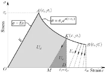
[image:2.595.200.397.443.558.2]Considering that confining pressure is usually less than 20 MPa after excavating cavern, thus the dominant mode should be elastic-strain softening for rock mass constitutive relationship, whose basic characteristic can be generalized as linear growth and exponential decline (see Figure 3).
Figure 1. Measured Stress-Strain Curve of Jinping Marble.
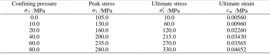
Table 1. Experimental parameters of Jinping marble under different confining pressure.
Confining pressure
3 σ /MPa
Peak stress
1 σ /MPa
Ultimate stress
1 σ /MPa
Ultimate strain m
ε /MPa
0.0 105.0 10.0 0.00560
10.0 130.0 60.0 0.00960
20.0 160.0 120.0 0.02260
40.0 200.0 215.0 0.03430
60.0 235.0 270.0 0.03565
80.0 280.0 330.0 0.04652
Determination of Basic Mechanical Parameters for Rock Mass under Different Confining Pressure
[image:2.595.70.524.605.697.2]By studying the stress-strain curve of Jinping marble in its whole process and referring to other tri-axial experimental results [3-5, 11-12], it is found that there is a good linear relationship between the above 3 parameters and confining pressure (see Figure 3)
P k ε ε P k σ σ P k σ σ m m c c c c 3 0 2 0 1 0 (1)
where P is confining pressure and can be taken as the minimum principal stress, σc0 is uni-axial
compressive strength, σc0 is ultimate stress of uni-axial compression, εm0 is ultimate strain of
[image:3.595.66.537.246.347.2]uni-axial compression, k1, k2 and k3 is coefficients for peak stress, ultimate stress and ultimate strain respectively, which can be obtained by curve fitting.
Figure 2. Fitting Curve of Basic Mechanical Parameters for Jinping Marble.
Determination of Energy Resistance and Dissipative Energy in Surrounding Rock
When rock mass is at the elastic stage OA, its strain will recover to zero after removing the external force, and all external work will be transformed into elastic strain energy. So there is no energy dissipation at this time. When stress state enters the softening or hardening stage AB, non-zero plastic deformation will occur after unloading (see Figure 3). At this moment, external work includes irrecoverable plastic dissipation energy Ud and releasable elastic strain energy Ue. Then total energy
U input from outside to rock mass system should be a sum of these two
e
d
U
U
U
(2)Figure 3. Energy Composition of Elastic-Strain Softening Model.
With the increase of external work, the stress state of rock mass gradually approaches to its bearing limit, and the proportion of elastic strain energy decreases gradually. When ultimate strain state is attained, the plastic dissipation energy reaches its maximum, while the elastic strain energy decreases to zero. According to the above process, self-resistant energy Urock in surrounding rock can
be defined as
εmrock
U
σdε
U
[image:3.595.208.385.514.636.2]Thus the physical meaning of surrounding rock's self-resistant energy is the area region OABC of complete stress-strain curve (see Figure 3). And that is to say, the maximum dissipated energy that rock mass can bear under a certain confining pressure [8].
Supposing the elastic modulus E of elastic stage OA for rock mass, the unloading modulus Eu of
point K in oftening stage, and the largest principal stress σ1 and strain 1 at point K. So plastic
dissipation energy Ud corresponding to softening stage at point K is the difference between area
OAKD and area MDK.
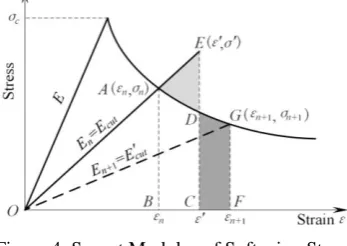
Determination of Secant Modulus
In order to avoid negative stiffness in global matrix, which is caused by the application of elasto-plastic FEM to strain softening materials, the stress and strain of rock mass can be determined by its secant modulus Ecut at any time
1
1
E
ε
σ
cut (4) [image:4.595.210.384.305.428.2]From this, it follows that secant modulus at elastic stage is always equal to elastic modulus in rock mass, and which is always positive at plastic stage.
Figure 4. Secant Modulus of Softening Stage.
During softening stage, the secant modulus, stress and strain at step n are assumed to be given (see point A in Figure 4). After applying current loading step, stress-strain state will exceed the softening curve, and rock mass will produce greater plastic deformation to completely counteract excess energy. When it reaches the true stress-strain state of step n+1 (see point G in Figure 4), strain and secant modulus at this state can be derived from the area equivalence relation UADE=UDCFG
n n nεn εc
c n c
n ε ε ε ε e
σ E n n ε ε 2 ln 1 1 (5)
εn εc
n n c n n n
e
ε
σ
ε
σ
E
11 1
1 1
(6) Based on derivation above, tangent elastic-plastic matrix for incremental constitutive relation can be replaced by secant elastic matrix, hence a new incremental stress-strain relationship can be established
Δε D
Δσ cut (7)
Energy Effect of Supporting Structure
Additional Resistant Energy for Supporting Structure Contributing to Surrounding Rock
bonding effect of interface, which is formed after grouting drilling holes of bolts or anchor cables with mortar. And the third one is provided by filling-bonding effect after grouting fissures around drilling holes in surrounding rock. In this way, additional resistant energy Uadd for supporting
[image:5.595.213.378.129.247.2]structure contributing to rock mass, can be obtained by summing up the above 3 factors.
Figure 5. Sketch of Bolt or Anchor Cable Increasing the Self-Resistant Energy of Surrounding Rock.
Improvement of Self-resistant Energy for Supporting Structure Acting on Surrounding Rock
Here the elastic-strain softening model under low confining pressure is analyzed. Firstly, through the input of additional resistant energy for supporting structure to surrounding rock, rock mass can still deform together with bolts or anchor cables at its own ultimate strain, thus enhancing ultimate strain. Secondly, additional lateral stress provided by bolts or anchor cables can increase confining pressure acting on surrounding rock, thus enhancing the peak compressive strength of rock mass (see Figure 5).
According to the analysis, supporting structure will increase self-resistant energy in surrounding rock from area OABC (without support) to area OA'B'C' (supported).
Energy Dissipation Ratio Criterion for Surrounding Rock's Failure
From energy dissipation theory, it can clearly be seen that surrounding rock's failure should be determined by both of these two parameters, peak compressive strength and ultimate strain.
Based on self-resistant energy a rock
U and plastic dissipation energy Uda of surrounding rock before
reinforcing, energy dissipation ratio a d
R determining rock mass state without support is defined as
a rock a d a d
U
U
R
(8)Because supporting structure generates energy input to surrounding rock, a new self-resistant energy b
rock
U of surrounding rock is obtained after applying bolts or anchor cables. On the basis of corresponding plastic dissipation energy b
d
U of surrounding rock after reinforcement, energy dissipation ratio b
d
R determining rock mass state and considering supporting effect can be defined as
add b rock b d total b d b d U U U U U R
(9)
Consequently, energy dissipation ratio is always between 0 and 1.0, and Energy dissipation ratio criterion for surrounding rock's failure can be expressed as follows.
1) Elastic state when a d
R or Rdb equals 0
2) Plastic state and partially destroyed when 0< a d
R or Rdb<Rcr
3) Completely destroyed when Rcr ≤Rda or Rdb≤1.0
where Rcr is a critical energy dissipation ratio, which can be taken as 0.90~0.95 in practice.
resistant energy, and its volume dilatation increases significantly, which will lead to sudden failure and destruction.
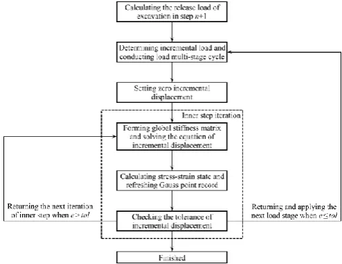
[image:6.595.173.420.224.414.2]Energy dissipation method (EDM) for surrounding rock's stability analysis
Figure 6 illustrates the calculating flow chart of EDM finite element for surrounding rock's stability analysis. Computational analysis is carried out by using the non-linear finite element analysis program NASGEWIN 2.0, which is developed and perfected by Department of Numerical Simulation in Geotechnical Engineering, Sichuan University. And this program has been successfully applied to study many major projects in China, such as Er'tan, Jinping, Xiaowan, Xiluodu, Pubugou and so on, containing powerful analysis functions.
Figure 6. Calculation Process of EDM Finite Element for Surrounding Rock's Stability Analysis.
Analysis of Surrounding rock's State and Failure for Jinping I Underground Powerhouse
Finite Element Model and Calculating Parameters
Figure 7 illustrates a 2D finite element model of unit block 5# in Jinping I underground powerhouse after excavation, which simulates the geological characteristics including strata, stratigraphic interfaces, lamprophyres vein X and faults (f14, f18) in detail, along with supporting structure composed of bolts and anchor cables. Besides, a total of 15649 nodes and 15457 elements are discretized, and among them 632 bolt and anchor cable elements are applied.
[image:6.595.186.413.625.747.2]Combined with stress-strain test, EDM calculation parameters of rock mass type III1 are selected as shown in Table 2 (type III1 is dominant in the engineering region), which is obtained by linear fitting between basic mechanical parameters of rock mass and confining pressure.
Table 2. EDM calculating parameters of rock mass type III1 in Jinping I underground powerhouse.
Parameter Symbol Value
Elastic modulus E (GPa) 15.0
Poisson ratio μ 0.25
Uniaxial compressive strength σc0 (MPa) 45.0
Peak stress coefficient k1 2.5
Ultimate stress of uniaxial compression σc0 (MPa) 6.5
Ultimate stress coefficient k2 2.5
Ultimate strain of uniaxial compression εm0 0.0050
Ultimate strain coefficient k3 0.0005
Distribution of Principal Stress Calculated by EDM in Surrounding Rock
[image:7.595.211.385.259.382.2]Figure 8~9 demonstrate a contour distribution of 1st principal stress under excavation condition, calculated by EDM in surrounding rock around the cavern.
Figure 8. 1st principal stress of surrounding rock (unsupported) with excavation completed (MPa).
Figure 9. 1st principal stress of surrounding rock (supported) with excavation completed (MPa).
Due to the release effect of excavation removing confining pressure, stress redistribution of surrounding rock is resulted in and circumferential stress gets a rise around the cavern. And this enables that largest principal stress appears a certain degree of concentration surrounding the cavern, especially obvious at upstream and downstream haunch, turning parts and intersection positions of 3 large caverns.
Stress concentration of main powerhouse mainly appears in arching areas of upstream and downstream as well as both sidewalls. Also its degree of stress concentration in downstream arching area is greater than that in upstream arching area. At the same time, similar phenomenon also exists in the arching area of main transformer hall and tailrace surge chamber.
Due to the influence of lamprophyres vein X, stress concentration between the upstream sidewall of main transformer hall and X is extremely prominent. Excavation has a significant effect on largest principal stress around the cavern, while other rock mass far from the excavation area remains basically unchanged.
Distribution of Total Resistant Energy Calculated by EDM in Surrounding Rock
Figure 10~11 demonstrate a contour distribution of total resistant energy calculated by EDM.
[image:7.595.212.382.403.522.2]pressure, total resistant energy of surrounding rock near the cavern outline possesses a minimum value, generally about 0.12MJ/m3. But larger confining pressure farther from the cavern outline, total resistance energy of rock mass increases gradually.
Bolts or anchor cables reinforcing will produce energy input to surrounding rock, which makes total resistant energy of rock mass increase obviously in a certain range around the cavern. Especially at upstream haunch of main powerhouse, whose total resistance energy increases to 1.30MJ/m3 due to intensive support of anchor cables, exceeding more than 10 times as much as that before supporting.
[image:8.595.211.383.213.335.2]Excavation has a remarkable impact on total energy resistance of surrounding rock near the cavern, while this energy remains unchanged basically far from the excavation area.
[image:8.595.212.382.358.477.2]Figure 10. Total resistant energy of surrounding rock (unsupported) with excavation completed (10-1MJ/m3).
Figure 11. Total resistant energy of surrounding rock (supported) with excavation completed (10-1MJ/m3).
Distribution of Total Resistant Energy Calculated by EDM in Surrounding Rock
Figure 12~15 demonstrate a contour distribution of energy dissipation zone calculated by EDM. Significant stress concentration will make rock mass enter the softening stage of energy dissipation, so energy dissipation zone is concentrated in a certain range nearby the cavern. Furthermore, high value district of energy dissipation ratio (Rd >0.9) is mainly located in upstream
and downstream haunch, turning parts and intersection positions of 3 large caverns. Surrounding rock in these areas is left in a dangerous state of critical failure, but its failure depth is obviously smaller after reinforcement, generally in a safe state of low value Rd <0.3.
Energy dissipation zone and its magnitude around the cavern are distinctly reduced after applying support. On the one hand, for some part of surrounding rock in initial softening stage before reinforcement, bolts or anchor cables reinforcing makes its stress-strain state readjust to elastic stage after reinforcement, hence no energy dissipation will occur at this point. On the other hand, for remaining surrounding rocks in softening middle or final stage before reinforcement, adjustment of stress state makes elastic strain energy take an increased proportion, but plastic dissipation energy decreases proportionally under the same external force. Together with surrounding rock's additional resistant energy contributed by supporting structure, the value Rd decreases obviously after reinforcement.
before reinforcement, namely 1.30m and 3.33m. In addition, the depth range of other failure zone is decreased in different degrees after reinforcing.
[image:9.595.185.411.240.357.2]Figure 12. Energy Dissipation Ratio Rd of Surrounding Rock with Excavation Completed (Unsupported).
[image:9.595.198.400.382.489.2]Figure 13. Energy Dissipation Ratio Rd of Surrounding Rock with Excavation Completed (Supported).
Figure 14. Energy Dissipation Zone of Surrounding Rock with Excavation Completed (Unsupported & Rd>0.9).
Figure 15. Energy dissipation zone of surrounding rock with excavation completed (supported & Rd>0.9).
[image:9.595.195.401.516.627.2] [image:9.595.74.521.642.754.2]Conclusions
According to the linear relationship between basic mechanical parameters of rock mass and current confining pressure, elastic-strain softening relationship considering different confining pressure states is proposed. Energy dissipation method (EDM) for surrounding rock's stability analysis is established by derivation, and calculating flow chart of EDM finite element is also given accordingly.
Additional resistant energy contributed by supporting structure to surrounding rock and the essence of increasing self-resistant energy in surrounding rock is expounded in detail, revealing profoundly the energy effect of support structure to surrounding rock. Based on energy dissipation ratio, the failure criterion of surrounding rock is put forward to consider supporting effect, which more reasonably explains the deformation failure of surrounding rock and the mechanical mechanism of supporting effect.
Taking Jinping I underground powerhouse as a research object, with the help of EDM finite element analysis for surrounding rock's stability, it has been proved that the reinforcement mechanism of supporting structure is to improve mechanical properties of surrounding rock, increase its total resistant energy, decrease energy dissipation zone, and reduce high dissipation ratio in rock mass from dangerous situation to safe state. In this way, the depth development of failure zone can be restrained and the cavern's stability can be ensured effectively.
Surrounding rock's failure criterion based on energy dissipation ratio has both practical value and rationality. And finite element analysis based on EDM for surrounding rock's stability can better predict the location and depth of its deformation failure.
References
[1] H.W. Zhou, H.P. Xie and J.P. Zuo. “Developments in researches on mechanical behaviors of rocks under the condition of high ground pressure in the depths”, J. Advances in Mechanics, vol. 35, pp. 91-99. February 2005.
[2] H.P. Xie. “Research framework and anticipated results of deep tock mechanics and mining theory”, J. Advanced Engineering Sciences, vol. 49, pp. 1-16, March 2017.
[3] W. R. Wawersik and C. Fairhurst. “A study of brittle rock fracture in laboratory compression experiments”, J. International Journal of Rock Mechanics and Mining Sciences & Geomechanics Abstracts, vol. 7, pp. 561-575, September 1970.
[4] Z.Y. Lin, Y.S. Wu and L.L. Guan. “Reasearch on the brittle-ductile transition property of rocks under triaxial compression,” J. Rock and Soil Mechanics, vol. 13, pp. 45-53, June 1992.
[5] S.L. Xu, W. Wu, G.Y. Wang, Q. H. Zhang and J. P. Xu. “Study on complete procedures of marble under triaxial compression I: Testing study on complete procedure of triaxial compression and the processes of unloading confining at the pre-peak and post-peak,” J. Chinese Journal of Rock Mechanics and Engineering, vol. 20, pp. 763-767, November 2001.
[6] Q.S. Liu, G.F. Lei and X.X. Peng. “Advance and review on the anchoring mechanism in deep fractured rock mass,” J. Chinese Journal of Rock Mechanics and Engineering, vol. 35(2), pp. 312-332, February 2016.
[7] A.Z. Hua. “Energy analysis of surrounding rocks in underground engineering,” J. Chinese Journal of Rock Mechanics and Engineering, vol. 22, pp. 1054-1059, July 2003.
[8] H.P. Xie, Y. Ju and L.Y. Li. “Criteria for strength and structural failure of rocks based on energy dissipation and energy release principles”, J. Chinese Journal of Rock Mechanics and Engineering, vol. 24, pp. 3003-3010, September 2005.
[10] Z.M. Xu, P.G. Wu, S.D. Wang and Z.G. Tang. “Analysis of energy released in process of rock-burst”, J. Journal of Natural Disasters, vol. 12, pp. 104-110, August 2003.
[11] S.Q. Yang, C.D. Su and W.Y. Xu. “Study on the deformation failure and energy properties of marble specimen under triaxial compression,” J. Rock and Soil Mechanics, vol. 24, pp. 136-142, March 2007.
[12] Y.D. Lu, X.R. Ge, Y. Jiang and J.X. Ren. “Study on conventional triaxial compression test of complete process for marble and its constitutive equation,” J. Chinese Journal of Rock Mechanics and Engineering, vol. 23, pp. 2489-2493, August 2004.